
Manual
Page 1
... to enable RAID for complex and time-consuming configurations. Exits the X.H.D utility: Click Cancel to automatically set up all motherboard drivers, including the X.H.D utility. All with which you have to Chapter 5, "Installing the SATA RAID/AHCI Driver and Operating System." ... 0 array that before you run the X.H.D utility, back up a RAID 0 array later using the Auto function. B. eXtreme Hard Drive (X.H.D) With GIGABYTE eXtreme Hard Drive (X.H.D)(Note 1), users can quickly configure a RAIDready system for RAID 0. Before installing the operating system, you can build a RAID 0, ...
... to enable RAID for complex and time-consuming configurations. Exits the X.H.D utility: Click Cancel to automatically set up all motherboard drivers, including the X.H.D utility. All with which you have to Chapter 5, "Installing the SATA RAID/AHCI Driver and Operating System." ... 0 array that before you run the X.H.D utility, back up a RAID 0 array later using the Auto function. B. eXtreme Hard Drive (X.H.D) With GIGABYTE eXtreme Hard Drive (X.H.D)(Note 1), users can quickly configure a RAIDready system for RAID 0. Before installing the operating system, you can build a RAID 0, ...
Manual
Page 1
GA-P55-UD3 LGA1156 socket motherboard for Intel® Core™ i7 processor family/ Intel® Core™ i5 processor family User's Manual Rev. 1001 12ME-P55UD3-1001R
GA-P55-UD3 LGA1156 socket motherboard for Intel® Core™ i7 processor family/ Intel® Core™ i5 processor family User's Manual Rev. 1001 12ME-P55UD3-1001R
Manual
Page 3
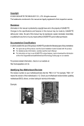
...on our website at: http://www.gigabyte.com.tw Identifying Your Motherboard Revision The revision number on how to assist in this product, GIGABYTE provides the following types of documentations: For quick set-up of the motherboard is the property of this manual ...included with the product. For instructions on your motherboard revision before updating motherboard BIOS, drivers, or when looking for technical information. The trademarks mentioned in any means without prior notice. Disclaimer Information in the use GIGABYTE's unique features, read the User's Manual....
...on our website at: http://www.gigabyte.com.tw Identifying Your Motherboard Revision The revision number on how to assist in this product, GIGABYTE provides the following types of documentations: For quick set-up of the motherboard is the property of this manual ...included with the product. For instructions on your motherboard revision before updating motherboard BIOS, drivers, or when looking for technical information. The trademarks mentioned in any means without prior notice. Disclaimer Information in the use GIGABYTE's unique features, read the User's Manual....
Manual
Page 4
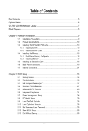
Table of Contents Box Contents...6 Optional Items...6 GA-P55-UD3 Motherboard Layout 7 Block Diagram...8 Chapter 1 Hardware Installation 9 1-1 Installation Precautions 9 1-2 Product Specifications 10 1-3 Installing the CPU and CPU Cooler 13 1-3-1 Installing the CPU 13 1-3-2 Installing the CPU ...
Table of Contents Box Contents...6 Optional Items...6 GA-P55-UD3 Motherboard Layout 7 Block Diagram...8 Chapter 1 Hardware Installation 9 1-1 Installation Precautions 9 1-2 Product Specifications 10 1-3 Installing the CPU and CPU Cooler 13 1-3-1 Installing the CPU 13 1-3-2 Installing the CPU ...
Manual
Page 6
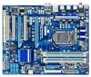
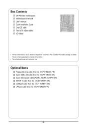
Box Contents GA-P55-UD3 motherboard Motherboard driver disk User's Manual Quick Installation Guide One IDE cable Two SATA 3Gb/s cables I/O Shield • The box contents above are subject to change without notice. • The motherboard image is for reference only and the actual items shall depend on the product package you obtain. Optional Items Floppy disk...
Box Contents GA-P55-UD3 motherboard Motherboard driver disk User's Manual Quick Installation Guide One IDE cable Two SATA 3Gb/s cables I/O Shield • The box contents above are subject to change without notice. • The motherboard image is for reference only and the actual items shall depend on the product package you obtain. Optional Items Floppy disk...
Manual
Page 7
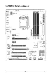
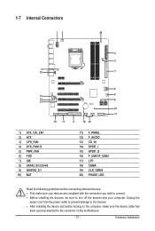
GA-P55-UD3 Motherboard Layout KB_USB R_SPDIF R_USB_3 R_USB_2 CPU_FAN ATX_12V_2X4 R_USB_1 USB_LAN SYS_FAN1 AUDIO F_AUDIO RTL8111D PCIEX16 PCIEX1_1 PCIEX1_2 CD_IN SPDIF_I SPDIF_O CODEC PCI1 PCIEX4 PCI2 IT8720 PCI3 LPT COMA LGA1156 PHASE LED ATX PWR_FAN GA-P55-UD3 DDR3_2 DDR3_1 DDR3_4 DDR3_3 IDE GIGABYTE SATA2 GSATA2_1 GSATA2_0 Intel® P55 SYS_FAN2 B_BIOS M_BIOS BAT CLR_CMOS FDD F_USB2 F_USB1 SATA2_3 SATA2_0 SATA2_4 SATA2_1 SATA2_5 SATA2_2 F_PANEL - 7 -
GA-P55-UD3 Motherboard Layout KB_USB R_SPDIF R_USB_3 R_USB_2 CPU_FAN ATX_12V_2X4 R_USB_1 USB_LAN SYS_FAN1 AUDIO F_AUDIO RTL8111D PCIEX16 PCIEX1_1 PCIEX1_2 CD_IN SPDIF_I SPDIF_O CODEC PCI1 PCIEX4 PCI2 IT8720 PCI3 LPT COMA LGA1156 PHASE LED ATX PWR_FAN GA-P55-UD3 DDR3_2 DDR3_1 DDR3_4 DDR3_3 IDE GIGABYTE SATA2 GSATA2_1 GSATA2_0 Intel® P55 SYS_FAN2 B_BIOS M_BIOS BAT CLR_CMOS FDD F_USB2 F_USB1 SATA2_3 SATA2_0 SATA2_4 SATA2_1 SATA2_5 SATA2_2 F_PANEL - 7 -
Manual
Page 9
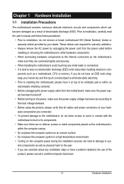
...8226; It is best to the use of electrostatic discharge (ESD). If you are connected tightly and securely. • When handling the motherboard, avoid touching any installation steps or have it on top of an antistatic pad or within the computer casing. • Do not ...; Before unplugging the power supply cable from the power outlet before installing or removing the motherboard or other hardware components. • When connecting hardware components to the internal connectors on the motherboard, make sure the power supply voltage has been set according to the local voltage standard....
...8226; It is best to the use of electrostatic discharge (ESD). If you are connected tightly and securely. • When handling the motherboard, avoid touching any installation steps or have it on top of an antistatic pad or within the computer casing. • Do not ...; Before unplugging the power supply cable from the power outlet before installing or removing the motherboard or other hardware components. • When connecting hardware components to the internal connectors on the motherboard, make sure the power supply voltage has been set according to the local voltage standard....
Manual
Page 12
... CPU/system fan speed control function is supported will depend on the CPU/system cooler you install. (Note 5) Available functions in EasyTune may differ by motherboard model.
... CPU/system fan speed control function is supported will depend on the CPU/system cooler you install. (Note 5) Available functions in EasyTune may differ by motherboard model.

Manual
Page 13
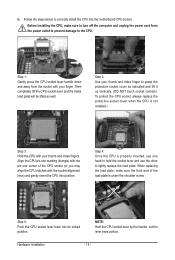
... do so according to your hardware specifications including the CPU, graphics card, memory, hard drive, etc. 1-3-1 Installing the CPU A. Locate the alignment keys on the motherboard CPU socket and the notches on the CPU - 13 - LGA1156 CPU Socket Alignment Key Alignment Key Pin One Corner of the CPU Socket LGA1156 CPU... the following guidelines before installing the CPU to prevent hardware damage. • Locate the pin one of the CPU. It is not recommended that the motherboard supports the CPU. (Go to GIGABYTE's website for the peripherals.
... do so according to your hardware specifications including the CPU, graphics card, memory, hard drive, etc. 1-3-1 Installing the CPU A. Locate the alignment keys on the motherboard CPU socket and the notches on the CPU - 13 - LGA1156 CPU Socket Alignment Key Alignment Key Pin One Corner of the CPU Socket LGA1156 CPU... the following guidelines before installing the CPU to prevent hardware damage. • Locate the pin one of the CPU. It is not recommended that the motherboard supports the CPU. (Go to GIGABYTE's website for the peripherals.
Manual
Page 14
... plate will be lifted as indicated and lift it up vertically. (DO NOT touch socket contacts. Step 5: Push the CPU socket lever back into the motherboard CPU socket.
... plate will be lifted as indicated and lift it up vertically. (DO NOT touch socket contacts. Step 5: Push the CPU socket lever back into the motherboard CPU socket.
Manual
Page 15
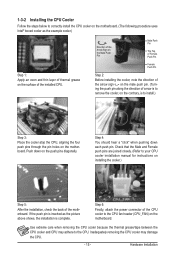
... CPU cooler may adhere to the CPU fan header (CPU_FAN) on the surface of the motherboard. Push down each push pin. Hardware Installation Step 4: You should hear a "click" when pushing down on the motherboard. Direction of the Arrow Sign on the Male Push Pin Male Push Pin The Top of...to remove the cooler, on the contrary, is inserted as the example cooler.) Step 1: Apply an even and thin layer of thermal grease on the motherboard. Step 6: Finally, attach the power connector of arrow is to install.) Step 3: Place the cooler atop the CPU, aligning the four push pins ...
... CPU cooler may adhere to the CPU fan header (CPU_FAN) on the surface of the motherboard. Push down each push pin. Hardware Installation Step 4: You should hear a "click" when pushing down on the motherboard. Direction of the Arrow Sign on the Male Push Pin Male Push Pin The Top of...to remove the cooler, on the contrary, is inserted as the example cooler.) Step 1: Apply an even and thin layer of thermal grease on the motherboard. Step 6: Finally, attach the power connector of arrow is to install.) Step 3: Place the cooler atop the CPU, aligning the four push pins ...

Manual
Page 16
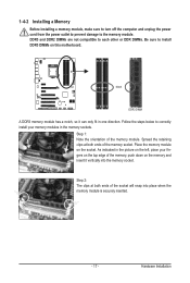
...Sided, "- -"=No Memory) DDR3_2 DDR3_1 DDR3_4 DDR3_3 Due to insert the memory, switch the direction. 1-4-1 Dual Channel Memory Configuration This motherboard provides four DDR3 memory sockets and supports Dual Channel Technology. When enabling Dual Channel mode with two memory modules, be sure to prevent... hardware damage. • Memory modules have a foolproof design. Dual Channel mode cannot be used . (Go to GIGABYTE's website for optimum performance. It is installed, the BIOS will double the original memory bandwidth. If you begin to install it in...
...Sided, "- -"=No Memory) DDR3_2 DDR3_1 DDR3_4 DDR3_3 Due to insert the memory, switch the direction. 1-4-1 Dual Channel Memory Configuration This motherboard provides four DDR3 memory sockets and supports Dual Channel Technology. When enabling Dual Channel mode with two memory modules, be sure to prevent... hardware damage. • Memory modules have a foolproof design. Dual Channel mode cannot be used . (Go to GIGABYTE's website for optimum performance. It is installed, the BIOS will double the original memory bandwidth. If you begin to install it in...
Manual
Page 17
... edge of the memory, push down on the memory and insert it can only fit in the memory sockets. Place the memory module on this motherboard. As indicated in the picture on the left, place your memory modules in one direction. Follow the steps below to the memory module. Step 2: The...
... edge of the memory, push down on the memory and insert it can only fit in the memory sockets. Place the memory module on this motherboard. As indicated in the picture on the left, place your memory modules in one direction. Follow the steps below to the memory module. Step 2: The...
Manual
Page 18
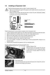
... the PCI Express slot. Remove the metal slot cover from the power outlet before you begin to install an expansion card: • Make sure the motherboard supports the expansion card. 1-5 Installing an Expansion Card Read the following guidelines before installing an expansion card to prevent hardware damage. Install the driver provided...
... the PCI Express slot. Remove the metal slot cover from the power outlet before you begin to install an expansion card: • Make sure the motherboard supports the expansion card. 1-5 Installing an Expansion Card Read the following guidelines before installing an expansion card to prevent hardware damage. Install the driver provided...
Manual
Page 19
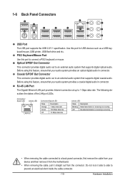
... audio. Coaxial S/PDIF Out Connector This connector provides digital audio out to an external audio system that your device and then remove it from the motherboard. • When removing the cable, pull it side to side to connect a PS/2 keyboard or mouse. Optical S/PDIF Out Connector This connector provides digital audio...
... audio. Coaxial S/PDIF Out Connector This connector provides digital audio out to an external audio system that your device and then remove it from the motherboard. • When removing the cable, pull it side to side to connect a PS/2 keyboard or mouse. Optical S/PDIF Out Connector This connector provides digital audio...
Manual
Page 21
..., make sure your devices are compliant with the connectors you wish to connect. • Before installing the devices, be sure to the connector on the motherboard. - 21 - Hardware Installation Unplug the power cord from the power outlet to prevent damage to the devices. • After installing the device and before connecting...
..., make sure your devices are compliant with the connectors you wish to connect. • Before installing the devices, be sure to the connector on the motherboard. - 21 - Hardware Installation Unplug the power cord from the power outlet to prevent damage to the devices. • After installing the device and before connecting...

Manual
Page 22
... unstable or unbootable system. • The power connectors are properly installed. If the 12V power connector is turned off and all the components on the motherboard. When using a power supply providing a 2x2 12V and a 2x10 power connector. 8 4 5 1 ATX_12V_2X4 ATX_12V_2X4: Pin No. Definition 1 GND (Only for 2x4-pin 12V) 2 GND (Only for... a power supply providing a 2x4 12V and a 2x12 power connector, remove the protective covers from the 12V power connector and the main power connector on the motherboard.
... unstable or unbootable system. • The power connectors are properly installed. If the 12V power connector is turned off and all the components on the motherboard. When using a power supply providing a 2x2 12V and a 2x10 power connector. 8 4 5 1 ATX_12V_2X4 ATX_12V_2X4: Pin No. Definition 1 GND (Only for 2x4-pin 12V) 2 GND (Only for... a power supply providing a 2x4 12V and a 2x12 power connector, remove the protective covers from the 12V power connector and the main power connector on the motherboard.
Manual
Page 23
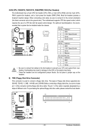
... a stripe of floppy disk drives supported are not configuration jumper blocks. The pin 1 of a CPU fan with fan speed control design. The motherboard supports CPU fan speed control, which requires the use of the cable is used to prevent your CPU and system from overheating. 3/4/5) CPU_FAN/SYS_FAN1.../SYS_FAN2/PWR_FAN (Fan Headers) The motherboard has a 4-pin CPU fan header (CPU_FAN), a 4-pin (SYS_FAN2) and two 3-pin (SYS_ FAN1) system fan headers, and a 3-pin power fan ...
... a stripe of floppy disk drives supported are not configuration jumper blocks. The pin 1 of a CPU fan with fan speed control design. The motherboard supports CPU fan speed control, which requires the use of the cable is used to prevent your CPU and system from overheating. 3/4/5) CPU_FAN/SYS_FAN1.../SYS_FAN2/PWR_FAN (Fan Headers) The motherboard has a 4-pin CPU fan header (CPU_FAN), a 4-pin (SYS_FAN2) and two 3-pin (SYS_ FAN1) system fan headers, and a 3-pin power fan ...

Manual
Page 27
... panel audio module to the header. Make sure the wire assignments of the module connector match the pin assignments of the motherboard header. Incorrect connection between the module connector and the motherboard header will be present on each wire instead of the front and back panel audio connections simultaneously. Definition 1 2 1 MIC2_L 1 MIC...
... panel audio module to the header. Make sure the wire assignments of the module connector match the pin assignments of the motherboard header. Incorrect connection between the module connector and the motherboard header will be present on each wire instead of the front and back panel audio connections simultaneously. Definition 1 2 1 MIC2_L 1 MIC...
Manual
Page 28
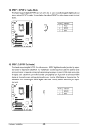
For information about connecting the S/PDIF digital audio cable, carefully read the manual for digital audio output from your motherboard to your graphics card if you to use a S/PDIF digital audio cable for your motherboard to certain expansion cards like graphics cards and sound cards. Definition 1 SPDIFO 2 GND 1 Hardware Installation - 28 - For example...
For information about connecting the S/PDIF digital audio cable, carefully read the manual for digital audio output from your motherboard to your graphics card if you to use a S/PDIF digital audio cable for your motherboard to certain expansion cards like graphics cards and sound cards. Definition 1 SPDIFO 2 GND 1 Hardware Installation - 28 - For example...


