Manual
Page 3
...trademarks mentioned in this manual are legally registered to the specifications and features in this manual may be made by GIGABYTE without GIGABYTE's prior written permission. Changes to their respective owners. No part of the motherboard is protected by any form or..., carefully read or download the information on/from the Support&Downloads\Motherboard\Technology Guide page on your motherboard revision before updating motherboard BIOS, drivers, or when looking for technical information. For example, "REV: 1.0" means the revision of this manual is 1.0. Documentation...
...trademarks mentioned in this manual are legally registered to the specifications and features in this manual may be made by GIGABYTE without GIGABYTE's prior written permission. Changes to their respective owners. No part of the motherboard is protected by any form or..., carefully read or download the information on/from the Support&Downloads\Motherboard\Technology Guide page on your motherboard revision before updating motherboard BIOS, drivers, or when looking for technical information. For example, "REV: 1.0" means the revision of this manual is 1.0. Documentation...
Manual
Page 4
Table of Contents Box Contents...6 Optional Items...6 GA-H55M-S2V/GA-H55M-S2 Motherboard Layout 7 GA-H55M-S2V/GA-H55M-S2 Motherboard Block Diagram 8 Chapter 1 Hardware Installation 9 1-1 Installation Precautions 9 1-2 Product Specifications 10 1-3 Installing the CPU...an Expansion Card 17 1-6 Back Panel Connectors 18 1-7 Internal Connectors 19 Chapter 2 BIOS Setup 27 2-1 Startup Screen 28 2-2 The Main Menu 29 2-3 MB Intelligent Tweaker(M.I.T 31 2-4 Standard CMOS Features 39 2-5 Advanced BIOS Features 41 2-6 Integrated Peripherals 43 2-7 Power Management Setup 46 2-8 PC Health ...
Table of Contents Box Contents...6 Optional Items...6 GA-H55M-S2V/GA-H55M-S2 Motherboard Layout 7 GA-H55M-S2V/GA-H55M-S2 Motherboard Block Diagram 8 Chapter 1 Hardware Installation 9 1-1 Installation Precautions 9 1-2 Product Specifications 10 1-3 Installing the CPU...an Expansion Card 17 1-6 Back Panel Connectors 18 1-7 Internal Connectors 19 Chapter 2 BIOS Setup 27 2-1 Startup Screen 28 2-2 The Main Menu 29 2-3 MB Intelligent Tweaker(M.I.T 31 2-4 Standard CMOS Features 39 2-5 Advanced BIOS Features 41 2-6 Integrated Peripherals 43 2-7 Power Management Setup 46 2-8 PC Health ...
Manual
Page 5
... 54 3-4 Contact...55 3-5 System...55 3-6 Download Center 56 3-7 New Utilities...56 Chapter 4 Unique Features 57 4-1 Xpress Recovery2 57 4-2 BIOS Update Utilities 60 4-2-1 Updating the BIOS with the Q-Flash Utility 60 4-2-2 Updating the BIOS with the @BIOS Utility 63 4-3 EasyTune 6...64 4-4 Q-Share...65 4-5 Auto Green...66 Chapter 5 Appendix...67 5-1 Configuring Audio Input and Output 67...
... 54 3-4 Contact...55 3-5 System...55 3-6 Download Center 56 3-7 New Utilities...56 Chapter 4 Unique Features 57 4-1 Xpress Recovery2 57 4-2 BIOS Update Utilities 60 4-2-1 Updating the BIOS with the Q-Flash Utility 60 4-2-2 Updating the BIOS with the @BIOS Utility 63 4-3 EasyTune 6...64 4-4 Q-Share...65 4-5 Auto Green...66 Chapter 5 Appendix...67 5-1 Configuring Audio Input and Output 67...
Manual
Page 8
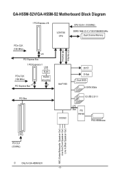
GA-H55M-S2V/GA-H55M-S2 Motherboard Block Diagram 1 PCI Express x16 LGA1156 CPU CPU CLK+/- (133 MHz) DDR3 1666 (O.C.)/1333/1066/800 MHz Dual Channel Memory PCIe CLK (100 MHz) x16 PCI Express Bus 1 PCI Express x1 LAN PCIe CLK (100 MHz) PCI Express Bus x1 RJ45 Realtek RTL8111E x1 Intel® H55 FDI Interface DMI Interface DVIj D-Sub Dual BIOS 6 SATA 3Gb/s PCI Bus 12 USB 2.0/1.1 CODEC LPC Bus iTE IT8720 PS/2 KB/Mouse 2 PCI PCI CLK (33 MHz) MIC (Center/Subwoofer Speakcer Out ) Line Out (Front Speakcer Out ) Line In (Rear Speakcer Out ) j Only for GA-H55M-S2V. - 8 -
GA-H55M-S2V/GA-H55M-S2 Motherboard Block Diagram 1 PCI Express x16 LGA1156 CPU CPU CLK+/- (133 MHz) DDR3 1666 (O.C.)/1333/1066/800 MHz Dual Channel Memory PCIe CLK (100 MHz) x16 PCI Express Bus 1 PCI Express x1 LAN PCIe CLK (100 MHz) PCI Express Bus x1 RJ45 Realtek RTL8111E x1 Intel® H55 FDI Interface DMI Interface DVIj D-Sub Dual BIOS 6 SATA 3Gb/s PCI Bus 12 USB 2.0/1.1 CODEC LPC Bus iTE IT8720 PS/2 KB/Mouse 2 PCI PCI CLK (33 MHz) MIC (Center/Subwoofer Speakcer Out ) Line Out (Front Speakcer Out ) Line In (Rear Speakcer Out ) j Only for GA-H55M-S2V. - 8 -
Manual
Page 11
... ports w 1 x RJ-45 port w 3 x audio jacks (Line In/Line Out/Microphone) I/O Controller w iTE IT8720 chip Hardware Monitor w w w w w w BIOS w w w w Unique Features w w w w w w w w w w System voltage detection CPU temperature detection CPU/System fan speed detection CPU overheating warning CPU/System fan...XP Form Factor w Micro ATX Form Factor; 24.4cm x 21.0cm j Only for GA-H55M-S2V. (Note 1) Due to Windows 32-bit operating system limitation, when more than 4 GB ...
... ports w 1 x RJ-45 port w 3 x audio jacks (Line In/Line Out/Microphone) I/O Controller w iTE IT8720 chip Hardware Monitor w w w w w w BIOS w w w w Unique Features w w w w w w w w w w System voltage detection CPU temperature detection CPU/System fan speed detection CPU overheating warning CPU/System fan...XP Form Factor w Micro ATX Form Factor; 24.4cm x 21.0cm j Only for GA-H55M-S2V. (Note 1) Due to Windows 32-bit operating system limitation, when more than 4 GB ...
Manual
Page 15
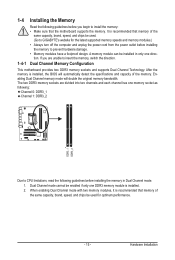
...the memory: • Make sure that memory of the same capacity, brand, speed, and chips be used . (Go to GIGABYTE's website for optimum performance. - 15 - Dual Channel Memory Configuration This motherboard provides two DDR3 memory sockets and supports Dual Channel ...Technology. Hardware Installation After the memory is installed, the BIOS will double the original memory bandwidth. When enabling Dual Channel mode with two memory modules, it is recommended that the motherboard ...
...the memory: • Make sure that memory of the same capacity, brand, speed, and chips be used . (Go to GIGABYTE's website for optimum performance. - 15 - Dual Channel Memory Configuration This motherboard provides two DDR3 memory sockets and supports Dual Channel ...Technology. Hardware Installation After the memory is installed, the BIOS will double the original memory bandwidth. When enabling Dual Channel mode with two memory modules, it is recommended that the motherboard ...
Manual
Page 17
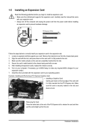
... cover from the slot. - 17 - Align the card with a screw. 5. Secure the card's metal bracket to make any required BIOS changes for your expansion card(s). 7. Hardware Installation If necessary, go to BIOS Setup to the chassis back panel with the slot, and press down on your operating system. Carefully read the manual...
... cover from the slot. - 17 - Align the card with a screw. 5. Secure the card's metal bracket to make any required BIOS changes for your expansion card(s). 7. Hardware Installation If necessary, go to BIOS Setup to the chassis back panel with the slot, and press down on your operating system. Carefully read the manual...
Manual
Page 22
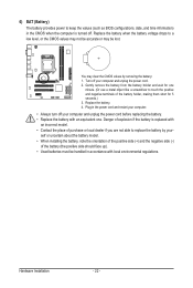
... cord before replacing the battery. • Replace the battery with local environmental regulations. 6) BAT (Battery) The battery provides power to keep the values (such as BIOS configurations, date, and time information) in the CMOS when the computer is replaced with an incorrect model. • Contact the place of purchase or local...
... cord before replacing the battery. • Replace the battery with local environmental regulations. 6) BAT (Battery) The battery provides power to keep the values (such as BIOS configurations, date, and time information) in the CMOS when the computer is replaced with an incorrect model. • Contact the place of purchase or local...

Manual
Page 23
... RESRES+ CICI+ PWR+ PWR- The system reports system startup status by chassis. If a problem is detected, the BIOS may differ by issuing a beep code. When connecting your system using the power switch (refer to Chapter 2, "BIOS Setup," "Power Management Setup," for information about beep codes. • HD (Hard Drive Activity LED, Blue...
... RESRES+ CICI+ PWR+ PWR- The system reports system startup status by chassis. If a problem is detected, the BIOS may differ by issuing a beep code. When connecting your system using the power switch (refer to Chapter 2, "BIOS Setup," "Power Management Setup," for information about beep codes. • HD (Hard Drive Activity LED, Blue...
Manual
Page 25
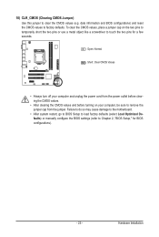
... a few seconds. Open: Normal Short: Clear CMOS Values • Always turn off your computer, be sure to factory defaults. Hardware Installation date information and BIOS configurations) and reset the CMOS values to remove the jumper cap from the power outlet before clearing the CMOS values. • After clearing the CMOS... turning on the two pins to temporarily short the two pins or use a metal object like a screwdriver to touch the two pins for BIOS configurations). - 25 - To clear the CMOS values, place a jumper cap on your computer and unplug the power cord from the jumper.
... a few seconds. Open: Normal Short: Clear CMOS Values • Always turn off your computer, be sure to factory defaults. Hardware Installation date information and BIOS configurations) and reset the CMOS values to remove the jumper cap from the power outlet before clearing the CMOS values. • After clearing the CMOS... turning on the two pins to temporarily short the two pins or use a metal object like a screwdriver to touch the two pins for BIOS configurations). - 25 - To clear the CMOS values, place a jumper cap on your computer and unplug the power cord from the jumper.
Manual
Page 27
... the current version of BIOS, it with caution. To flash the BIOS, do not encounter problems using the Q-Flash and @BIOS utilities, refer to boot. When the power is recommended that you not flash the BIOS. To upgrade the BIOS, use either the GIGABYTE Q-Flash or @BIOS utility. • ... It is recommended that you not alter the default settings (unless you can press + in system's failure to Chapter 4, "BIOS Update Utilities." • Because BIOS flashing is a Windows-based utility that allows the user to modify basic system configuration settings or to clear the CMOS values.) ...
... the current version of BIOS, it with caution. To flash the BIOS, do not encounter problems using the Q-Flash and @BIOS utilities, refer to boot. When the power is recommended that you not flash the BIOS. To upgrade the BIOS, use either the GIGABYTE Q-Flash or @BIOS utility. • ... It is recommended that you not alter the default settings (unless you can press + in system's failure to Chapter 4, "BIOS Update Utilities." • Because BIOS flashing is a Windows-based utility that allows the user to modify basic system configuration settings or to clear the CMOS values.) ...
Manual
Page 28
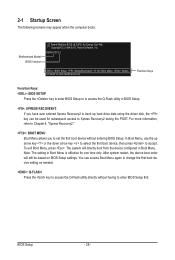
... to change the first boot device setting as needed. : Q-FLASH Press the key to access the Q-Flash utility directly without entering BIOS Setup. BIOS Setup - 28 - 2-1 Startup Screen The following screens may appear when the computer boots. After system restart, the device boot order...Menu. You can be based on BIOS Setup settings. H55M-S2V E1 . . . . : BIOS Setup : XpressRecovery2 : Boot Menu : Qflash 07/09/2010-H55-7A89TG0YC-00 Function Keys Function Keys: : BIOS SETUP Press the key to enter BIOS Setup or to access the Q-Flash utility in BIOS Setup. : XPRESS RECOVERY2 If ...
... to change the first boot device setting as needed. : Q-FLASH Press the key to access the Q-Flash utility directly without entering BIOS Setup. BIOS Setup - 28 - 2-1 Startup Screen The following screens may appear when the computer boots. After system restart, the device boot order...Menu. You can be based on BIOS Setup settings. H55M-S2V E1 . . . . : BIOS Setup : XpressRecovery2 : Boot Menu : Qflash 07/09/2010-H55-7A89TG0YC-00 Function Keys Function Keys: : BIOS SETUP Press the key to enter BIOS Setup or to access the Q-Flash utility in BIOS Setup. : XPRESS RECOVERY2 If ...
Manual
Page 29
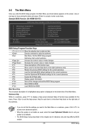
...of the Main Menu. Use arrow keys to move among the items and press to accept or enter a sub-menu. (Sample BIOS Version: GA-H55M-S2V E1) CMOS Setup Utility-Copyright (C) 1984-2010 Award Software MB Intelligent Tweaker(M.I.T.) Standard CMOS Features Advanced... BIOS Features Integrated Peripherals Power Management Setup PC Health Status ESC: Quit F8: Q-Flash Load Fail-Safe ...
...of the Main Menu. Use arrow keys to move among the items and press to accept or enter a sub-menu. (Sample BIOS Version: GA-H55M-S2V E1) CMOS Setup Utility-Copyright (C) 1984-2010 Award Software MB Intelligent Tweaker(M.I.T.) Standard CMOS Features Advanced... BIOS Features Integrated Peripherals Power Management Setup PC Health Status ESC: Quit F8: Q-Flash Load Fail-Safe ...
Manual
Page 30
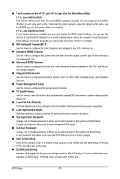
...First enter the profile name (to erase the default profile name, use the SPACE key) and then press to complete. F12: Load CMOS from BIOS If your CPU, memory, etc. Standard CMOS Features Use this menu to configure the system time and date, hard drive types, and the type... of errors that stop the system boot, etc. Advanced BIOS Features Use this menu to configure the device boot order, advanced features available on the CPU, and the primary display adapter. Integrated Peripherals Use...
...First enter the profile name (to erase the default profile name, use the SPACE key) and then press to complete. F12: Load CMOS from BIOS If your CPU, memory, etc. Standard CMOS Features Use this menu to configure the system time and date, hard drive types, and the type... of errors that stop the system boot, etc. Advanced BIOS Features Use this menu to configure the device boot order, advanced features available on the CPU, and the primary display adapter. Integrated Peripherals Use...
Manual
Page 31
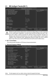
... Miscellaneous Settings [Press Enter] [Press Enter] [Press Enter] [Press Enter] [Press Enter] Item Help Menu Level BIOS Version BCLK CPU Frequency Memory Frequency Total Memory Size E1 133.27 MHz 3198.42 MHz 1332.80 MHz 1024 MB CPU Temperature ...Inadequately altering the settings may result in system's failure to CPU, chipset, or memory and reduce the useful life of these components. BIOS Setup 2-3 MB Intelligent Tweaker(M.I.T.) CMOS Setup Utility-Copyright (C) 1984-2010 Award Software MB Intelligent Tweaker(M.I.T.) } M.I .T. Incorrectly doing ...
... Miscellaneous Settings [Press Enter] [Press Enter] [Press Enter] [Press Enter] [Press Enter] Item Help Menu Level BIOS Version BCLK CPU Frequency Memory Frequency Total Memory Size E1 133.27 MHz 3198.42 MHz 1332.80 MHz 1024 MB CPU Temperature ...Inadequately altering the settings may result in system's failure to CPU, chipset, or memory and reduce the useful life of these components. BIOS Setup 2-3 MB Intelligent Tweaker(M.I.T.) CMOS Setup Utility-Copyright (C) 1984-2010 Award Software MB Intelligent Tweaker(M.I.T.) } M.I .T. Incorrectly doing ...
Manual
Page 32
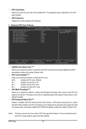
...supports this setting. (Default: Auto) (Note) This item is dependent on the CPU being installed. All Enables all CPU cores. Auto lets the BIOS automatically configure this setting. (Default: Auto) CPU Cores Enabled (Note) Allows you install a CPU that supports this feature. Auto lets the... BIOS automatically configure this function. CPU Multi-Threading (Note) Allows you to determine whether to enable multi-threading technology when using an Intel CPU...
...supports this setting. (Default: Auto) (Note) This item is dependent on the CPU being installed. All Enables all CPU cores. Auto lets the BIOS automatically configure this setting. (Default: Auto) CPU Cores Enabled (Note) Allows you install a CPU that supports this feature. Auto lets the... BIOS automatically configure this function. CPU Multi-Threading (Note) Allows you to determine whether to enable multi-threading technology when using an Intel CPU...
Manual
Page 33
...QPI link speed. >>>>> Standard Clock Control Base Clock(BCLK) Control Enables or disables the control of CPU base clock. Auto lets the BIOS automatically configure this setting. (Default) When the CPU or chipset detects that the CPU frequency be reduced when the CPU is enabled....(Mhz) Allows you install a CPU that supports this feature. ting. (Default: Auto) Bi-Directional PROCHOT (Note) Auto Enabled Disabled Lets the BIOS automatically configure this set- QPI Clock Ratio Allows you to determine whether to let the CPU enter C3/C6/C7 mode in accordance with unlocked...
...QPI link speed. >>>>> Standard Clock Control Base Clock(BCLK) Control Enables or disables the control of CPU base clock. Auto lets the BIOS automatically configure this setting. (Default) When the CPU or chipset detects that the CPU frequency be reduced when the CPU is enabled....(Mhz) Allows you install a CPU that supports this feature. ting. (Default: Auto) Bi-Directional PROCHOT (Note) Auto Enabled Disabled Lets the BIOS automatically configure this set- QPI Clock Ratio Allows you to determine whether to let the CPU enter C3/C6/C7 mode in accordance with unlocked...
Manual
Page 34
Extreme Memory Profile (X.M.P.) (Note) Allows the BIOS to read the SPD data on XMP memory module(s) to the BCLK Frequency(Mhz) and System Memory Multiplier settings. Profile2 (Note) Uses Profile 2 settings. Auto ... to manually set the PCIe clock frequency. System Memory Multiplier (SPD) Allows you to set the Chipset clock prior to set the onboard graphics clock. BIOS Setup - 34 - Options are : 700mV, 800mV, 900mV (default), 1000mV. Options are : 0ps~750ps. (Default: 0ps) PCH Clock Skew Allows you to the CPU clock. Auto...
Extreme Memory Profile (X.M.P.) (Note) Allows the BIOS to read the SPD data on XMP memory module(s) to the BCLK Frequency(Mhz) and System Memory Multiplier settings. Profile2 (Note) Uses Profile 2 settings. Auto ... to manually set the PCIe clock frequency. System Memory Multiplier (SPD) Allows you to set the Chipset clock prior to set the onboard graphics clock. BIOS Setup - 34 - Options are : 700mV, 800mV, 900mV (default), 1000mV. Options are : 0ps~750ps. (Default: 0ps) PCH Clock Skew Allows you to the CPU clock. Auto...
Manual
Page 35
.... Profile QPI Voltage The value displayed here is set to Disabled, this item will display as 1.5V. Performance Enhance Allows the system to be configurable. BIOS Setup Options are synchronous to those under the same items on the XMP memory. Profile DDR Voltage When using a non-XMP memory module or Extreme...
.... Profile QPI Voltage The value displayed here is set to Disabled, this item will display as 1.5V. Performance Enhance Allows the system to be configurable. BIOS Setup Options are synchronous to those under the same items on the XMP memory. Profile DDR Voltage When using a non-XMP memory module or Extreme...

Manual
Page 36
... Options are : Auto (default), 1~255. tWL Options are: Auto (default), 1~10 tRFC Options are : Auto (default), 1~31. ESC: Exit F1: General Help F7: Optimized Defaults BIOS Setup - 36 - tRP Options are : Auto (default), 1~15. tRCD Options are : Auto (default), 1~15. >>>>> Channel A/B Timing Settings CMOS Setup Utility-Copyright (C) 1984-2010 Award Software...
... Options are : Auto (default), 1~255. tWL Options are: Auto (default), 1~10 tRFC Options are : Auto (default), 1~31. ESC: Exit F1: General Help F7: Optimized Defaults BIOS Setup - 36 - tRP Options are : Auto (default), 1~15. tRCD Options are : Auto (default), 1~15. >>>>> Channel A/B Timing Settings CMOS Setup Utility-Copyright (C) 1984-2010 Award Software...


