Manual
Page 1
GA-H55M-S2V GA-H55M-S2 LGA1156 socket motherboard for Intel® Core™ i7 processors/Intel® Core™ i5 processors/Intel® Core™ i3 processors/Intel® Pentium® processors User's Manual Rev. 1301 12ME-H55MS2V-1301R
GA-H55M-S2V GA-H55M-S2 LGA1156 socket motherboard for Intel® Core™ i7 processors/Intel® Core™ i5 processors/Intel® Core™ i3 processors/Intel® Pentium® processors User's Manual Rev. 1301 12ME-H55MS2V-1301R
Manual
Page 2
Motherboard GA-H55M-S2V/GA-H55M-S2 Aug. 6, 2010 Motherboard GA-H55M-S2V GA-H55M-S2 Aug. 6, 2010
Motherboard GA-H55M-S2V/GA-H55M-S2 Aug. 6, 2010 Motherboard GA-H55M-S2V GA-H55M-S2 Aug. 6, 2010
Manual
Page 3
...order to the specifications and features in the use GIGABYTE's unique features, read or download the information on/from the Support&Downloads\Motherboard\Technology Guide page on your motherboard revision before updating motherboard BIOS, drivers, or when looking for technical ...manual may be reproduced, copied, translated, transmitted, or published in this product, GIGABYTE provides the following types of GIGABYTE. For example, "REV: 1.0" means the revision of the motherboard is the property of documentations: For detailed product information, carefully read the...
...order to the specifications and features in the use GIGABYTE's unique features, read or download the information on/from the Support&Downloads\Motherboard\Technology Guide page on your motherboard revision before updating motherboard BIOS, drivers, or when looking for technical ...manual may be reproduced, copied, translated, transmitted, or published in this product, GIGABYTE provides the following types of GIGABYTE. For example, "REV: 1.0" means the revision of the motherboard is the property of documentations: For detailed product information, carefully read the...
Manual
Page 4
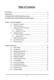
Table of Contents Box Contents...6 Optional Items...6 GA-H55M-S2V/GA-H55M-S2 Motherboard Layout 7 GA-H55M-S2V/GA-H55M-S2 Motherboard Block Diagram 8 Chapter 1 Hardware Installation 9 1-1 Installation Precautions 9 1-2 Product Specifications 10 1-3 Installing the CPU and CPU Cooler 12 1-3-1 Installing the CPU 12 1-3-2 Installing the CPU Cooler ...
Table of Contents Box Contents...6 Optional Items...6 GA-H55M-S2V/GA-H55M-S2 Motherboard Layout 7 GA-H55M-S2V/GA-H55M-S2 Motherboard Block Diagram 8 Chapter 1 Hardware Installation 9 1-1 Installation Precautions 9 1-2 Product Specifications 10 1-3 Installing the CPU and CPU Cooler 12 1-3-1 Installing the CPU 12 1-3-2 Installing the CPU Cooler ...
Manual
Page 6
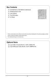
Box Contents GA-H55M-S2V or GA-H55M-S2 motherboard Motherboard driver disk User's Manual Two SATA cables I/O Shield • The box contents above are subject to change without notice. • The motherboard image is for reference only and the actual items shall depend on the product package you obtain. Optional Items 2-port USB 2.0 bracket (Part No. 12CR1-1UB030-5*R) 2-port SATA power cable (Part No. 12CF1-2SERPW-0*R) - 6 - The box contents are for reference only.
Box Contents GA-H55M-S2V or GA-H55M-S2 motherboard Motherboard driver disk User's Manual Two SATA cables I/O Shield • The box contents above are subject to change without notice. • The motherboard image is for reference only and the actual items shall depend on the product package you obtain. Optional Items 2-port USB 2.0 bracket (Part No. 12CR1-1UB030-5*R) 2-port SATA power cable (Part No. 12CF1-2SERPW-0*R) - 6 - The box contents are for reference only.

Manual
Page 7
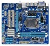
DVIj VGA DDR3_1 DDR3_2 SATA2_5 SATA2_2 SATA2_4 SATA2_1 SATA2_3 SATA2_0 GA-H55M-S2V/GA-H55M-S2 Motherboard Layout KB_MS ATX_12V Level Shifterj R_USB3 LGA1156 R_USB2 R_USB1 CPU_FAN USB_LAN AUDIO F_AUDIO PCIEX16 Realtek PCI1 RTL8111E PCI2 BAT GA-H55M-S2V GA-H55M-S2 Intel® H55 CODEC PCIEX1 SYS_FAN F_USB2 F_USB1 iTE IT8720 ATX M_BIOS B_BIOS CLR_CMOS F_PANEL j Only for GA-H55M-S2V. - 7 -
DVIj VGA DDR3_1 DDR3_2 SATA2_5 SATA2_2 SATA2_4 SATA2_1 SATA2_3 SATA2_0 GA-H55M-S2V/GA-H55M-S2 Motherboard Layout KB_MS ATX_12V Level Shifterj R_USB3 LGA1156 R_USB2 R_USB1 CPU_FAN USB_LAN AUDIO F_AUDIO PCIEX16 Realtek PCI1 RTL8111E PCI2 BAT GA-H55M-S2V GA-H55M-S2 Intel® H55 CODEC PCIEX1 SYS_FAN F_USB2 F_USB1 iTE IT8720 ATX M_BIOS B_BIOS CLR_CMOS F_PANEL j Only for GA-H55M-S2V. - 7 -
Manual
Page 8
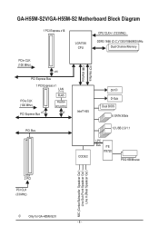
GA-H55M-S2V/GA-H55M-S2 Motherboard Block Diagram 1 PCI Express x16 LGA1156 CPU CPU CLK+/- (133 MHz) DDR3 1666 (O.C.)/1333/1066/800 MHz Dual Channel Memory PCIe CLK (100 MHz) x16 PCI Express Bus 1 PCI Express x1 LAN PCIe CLK (100 MHz) PCI Express Bus x1 RJ45 Realtek RTL8111E x1 Intel® H55 FDI Interface DMI Interface DVIj D-Sub Dual BIOS 6 SATA 3Gb/s PCI Bus 12 USB 2.0/1.1 CODEC LPC Bus iTE IT8720 PS/2 KB/Mouse 2 PCI PCI CLK (33 MHz) MIC (Center/Subwoofer Speakcer Out ) Line Out (Front Speakcer Out ) Line In (Rear Speakcer Out ) j Only for GA-H55M-S2V. - 8 -
GA-H55M-S2V/GA-H55M-S2 Motherboard Block Diagram 1 PCI Express x16 LGA1156 CPU CPU CLK+/- (133 MHz) DDR3 1666 (O.C.)/1333/1066/800 MHz Dual Channel Memory PCIe CLK (100 MHz) x16 PCI Express Bus 1 PCI Express x1 LAN PCIe CLK (100 MHz) PCI Express Bus x1 RJ45 Realtek RTL8111E x1 Intel® H55 FDI Interface DMI Interface DVIj D-Sub Dual BIOS 6 SATA 3Gb/s PCI Bus 12 USB 2.0/1.1 CODEC LPC Bus iTE IT8720 PS/2 KB/Mouse 2 PCI PCI CLK (33 MHz) MIC (Center/Subwoofer Speakcer Out ) Line Out (Front Speakcer Out ) Line In (Rear Speakcer Out ) j Only for GA-H55M-S2V. - 8 -
Manual
Page 9
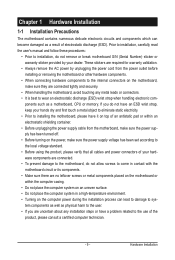
...- ponents such as a result of an antistatic pad or within an electrostatic shielding container. • Before unplugging the power supply cable from the motherboard, make sure the power supply has been turned off. • Before turning on the power, make sure they are uncertain about any metal leads ...or connectors. • It is best to installing the motherboard, please have an ESD wrist strap, keep your dealer. These stickers are required for warranty validation. • Always remove the AC power by...
...- ponents such as a result of an antistatic pad or within an electrostatic shielding container. • Before unplugging the power supply cable from the motherboard, make sure the power supply has been turned off. • Before turning on the power, make sure they are uncertain about any metal leads ...or connectors. • It is best to installing the motherboard, please have an ESD wrist strap, keep your dealer. These stickers are required for warranty validation. • Always remove the AC power by...
Manual
Page 11
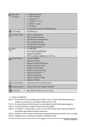
... Internet Security (OEM version) Operating System w Support for Microsoft® Windows 7/Vista/XP Form Factor w Micro ATX Form Factor; 24.4cm x 21.0cm j Only for GA-H55M-S2V. (Note 1) Due to Windows 32-bit operating system limitation, when more than 4 GB of physical memory is installed, the actual memory size displayed will be... 5) Whether the CPU fan speed control function is supported will depend on the CPU cooler you install. (Note 6) Available functions in EasyTune may differ by motherboard model. - 11 - Hardware Installation
... Internet Security (OEM version) Operating System w Support for Microsoft® Windows 7/Vista/XP Form Factor w Micro ATX Form Factor; 24.4cm x 21.0cm j Only for GA-H55M-S2V. (Note 1) Due to Windows 32-bit operating system limitation, when more than 4 GB of physical memory is installed, the actual memory size displayed will be... 5) Whether the CPU fan speed control function is supported will depend on the CPU cooler you install. (Note 6) Available functions in EasyTune may differ by motherboard model. - 11 - Hardware Installation

Manual
Page 12
... socket and the notches on the computer if the CPU cooler is not recommended that the motherboard supports the CPU. (Go to GIGABYTE's website for the peripherals. The CPU cannot be set the frequency beyond hardware specifications since it does not meet the standard requirements for the latest ...
... socket and the notches on the computer if the CPU cooler is not recommended that the motherboard supports the CPU. (Go to GIGABYTE's website for the peripherals. The CPU cannot be set the frequency beyond hardware specifications since it does not meet the standard requirements for the latest ...
Manual
Page 13
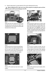
... hand to hold the socket lever and use the other to lightly replace the load plate. Step 5: Push the CPU socket lever back into the motherboard CPU socket. Hardware Installation Step 1: Gently press the CPU socket lever handle down on the rear grip of the socket cover and use one corner...
... hand to hold the socket lever and use the other to lightly replace the load plate. Step 5: Push the CPU socket lever back into the motherboard CPU socket. Hardware Installation Step 1: Gently press the CPU socket lever handle down on the rear grip of the socket cover and use one corner...
Manual
Page 14
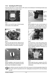
...along the direction of the installed CPU. Push down each push pin. Step 4: You should hear a "click" when pushing down on the motherboard. Use extreme care when removing the CPU cooler because the thermal grease/tape between the CPU cooler and CPU may damage the CPU. Hardware Installation...on the surface of arrow is to remove the cooler, on the contrary, is complete. Step 6: Finally, attach the power connector of the motherboard. Check that the Male and Female push pins are joined closely. (Refer to your CPU cooler installation manual for instructions on installing the cooler.)...
...along the direction of the installed CPU. Push down each push pin. Step 4: You should hear a "click" when pushing down on the motherboard. Use extreme care when removing the CPU cooler because the thermal grease/tape between the CPU cooler and CPU may damage the CPU. Hardware Installation...on the surface of arrow is to remove the cooler, on the contrary, is complete. Step 6: Finally, attach the power connector of the motherboard. Check that the Male and Female push pins are joined closely. (Refer to your CPU cooler installation manual for instructions on installing the cooler.)...
Manual
Page 15
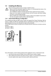
...original memory bandwidth. The two DDR3 memory sockets are unable to install the memory: • Make sure that the motherboard supports the memory. Hardware Installation Enabling Dual Channel memory mode will automatically detect the specifications and capacity of the memory...following: Channel 0: DDR3_1 Channel 1: DDR3_2 DDR3_1 DDR3_2 Due to CPU limitations, read the following guidelines before installing the memory to GIGABYTE's website for optimum performance. - 15 - 1-4 Installing the Memory 1-4-1 Read the following guidelines before installing the memory in only ...
...original memory bandwidth. The two DDR3 memory sockets are unable to install the memory: • Make sure that the motherboard supports the memory. Hardware Installation Enabling Dual Channel memory mode will automatically detect the specifications and capacity of the memory...following: Channel 0: DDR3_1 Channel 1: DDR3_2 DDR3_1 DDR3_2 Due to CPU limitations, read the following guidelines before installing the memory to GIGABYTE's website for optimum performance. - 15 - 1-4 Installing the Memory 1-4-1 Read the following guidelines before installing the memory in only ...
Manual
Page 16
... in one direction. Follow the steps below to the memory module. Hardware Installation - 16 - Step 1: Note the orientation of the memory, push down on this motherboard. Place the memory module on the socket. 1-4-2 Installing a Memory Before installing a memory module, make sure to turn off the computer and unplug the power cord...
... in one direction. Follow the steps below to the memory module. Hardware Installation - 16 - Step 1: Note the orientation of the memory, push down on this motherboard. Place the memory module on the socket. 1-4-2 Installing a Memory Before installing a memory module, make sure to turn off the computer and unplug the power cord...
Manual
Page 17
... chassis cover(s). 6. PCI Express x16 Slot PCI Slot PCI Express x1 Slot Follow the steps below to install an expansion card: • Make sure the motherboard supports the expansion card. Align the card with a screw. 5.
... chassis cover(s). 6. PCI Express x16 Slot PCI Slot PCI Express x1 Slot Follow the steps below to install an expansion card: • Make sure the motherboard supports the expansion card. Align the card with a screw. 5.
Manual
Page 18
... jack. Do not rock it side to side to a back panel connector, first remove the cable from your device and then remove it from the motherboard. • When removing the cable, pull it straight out from the connector. RJ-45 LAN Port The Gigabit Ethernet LAN port provides Internet connection at... a 15-pin D-Sub connector. Mic In Jack (Pink) The default Mic in jack. DVI-D Port j (Note 2) The DVI-D port conforms to this audio jack for GA-H55M-S2V (Note 1) To use an HD front panel audio module and enable the multi-channel audio feature through the audio driver.
... jack. Do not rock it side to side to a back panel connector, first remove the cable from your device and then remove it from the motherboard. • When removing the cable, pull it straight out from the connector. RJ-45 LAN Port The Gigabit Ethernet LAN port provides Internet connection at... a 15-pin D-Sub connector. Mic In Jack (Pink) The default Mic in jack. DVI-D Port j (Note 2) The DVI-D port conforms to this audio jack for GA-H55M-S2V (Note 1) To use an HD front panel audio module and enable the multi-channel audio feature through the audio driver.
Manual
Page 19
..., make sure your devices are compliant with the connectors you wish to connect. • Before installing the devices, be sure to the connector on the motherboard. - 19 -
..., make sure your devices are compliant with the connectors you wish to connect. • Before installing the devices, be sure to the connector on the motherboard. - 19 -
Manual
Page 20
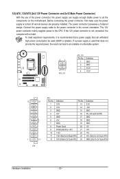
... connector in the correct orientation. The power connector possesses a foolproof design. To meet expansion requirements, it is turned off and all the components on the motherboard. Connect the power supply cable to the CPU. If a power supply is not connected, the computer will not start. 1/2) ATX_12V/ATX (2x2 12V Power Connector...
... connector in the correct orientation. The power connector possesses a foolproof design. To meet expansion requirements, it is turned off and all the components on the motherboard. Connect the power supply cable to the CPU. If a power supply is not connected, the computer will not start. 1/2) ATX_12V/ATX (2x2 12V Power Connector...
Manual
Page 21
The motherboard supports CPU fan speed control, which requires the use of the SATA cable to your CPU and system from overheating. Hardware Installation Definition 1 GND 2 +12V / ... wire). Each SATA connector supports a single SATA device. Please connect the L-shaped end of a CPU fan with SATA 1.5Gb/s standard. 3/4) CPU_FAN/SYS_FAN (Fan Headers) The motherboard has a 4-pin CPU fan header (CPU_FAN) and a 3-pin system fan header (SYS_FAN). For optimum heat dissipation, it in damage to SATA 3Gb/s standard and are...
The motherboard supports CPU fan speed control, which requires the use of the SATA cable to your CPU and system from overheating. Hardware Installation Definition 1 GND 2 +12V / ... wire). Each SATA connector supports a single SATA device. Please connect the L-shaped end of a CPU fan with SATA 1.5Gb/s standard. 3/4) CPU_FAN/SYS_FAN (Fan Headers) The motherboard has a 4-pin CPU fan header (CPU_FAN) and a 3-pin system fan header (SYS_FAN). For optimum heat dissipation, it in damage to SATA 3Gb/s standard and are...

Manual
Page 24
...an optional USB bracket. Hardware Installation - 24 - For information about connecting the front panel audio module that has separated connectors on both of the motherboard header. For purchasing the optional USB bracket, please contact the local dealer. Make sure the wire assignments of the module connector match the pin ... when using an HD front panel audio module), refer to work or even damage it. Incorrect connection between the module connector and the motherboard header will be sure to turn off your chassis front panel audio module to USB 2.0/1.1 specification.
...an optional USB bracket. Hardware Installation - 24 - For information about connecting the front panel audio module that has separated connectors on both of the motherboard header. For purchasing the optional USB bracket, please contact the local dealer. Make sure the wire assignments of the module connector match the pin ... when using an HD front panel audio module), refer to work or even damage it. Incorrect connection between the module connector and the motherboard header will be sure to turn off your chassis front panel audio module to USB 2.0/1.1 specification.


