Manual
Page 3
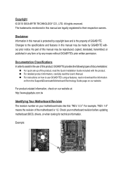
...or download the information on/from the Support&Downloads\Motherboard\Technology Guide page on your motherboard revision before updating motherboard BIOS, drivers, or when looking for technical information. All rights reserved. Documentation Classifications In order to assist in ...this manual are legally registered to use of this manual may be made by GIGABYTE without GIGABYTE's prior written permission. For detailed product information, carefully read the Quick Installation Guide included with the product. For product-...
...or download the information on/from the Support&Downloads\Motherboard\Technology Guide page on your motherboard revision before updating motherboard BIOS, drivers, or when looking for technical information. All rights reserved. Documentation Classifications In order to assist in ...this manual are legally registered to use of this manual may be made by GIGABYTE without GIGABYTE's prior written permission. For detailed product information, carefully read the Quick Installation Guide included with the product. For product-...
Manual
Page 4
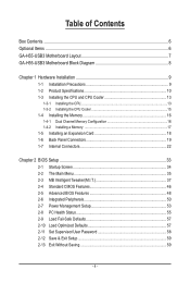
Table of Contents Box Contents...6 Optional Items...6 GA-H55-USB3 Motherboard Layout 7 GA-H55-USB3 Motherboard Block Diagram 8 Chapter 1 Hardware Installation 9 1-1 Installation Precautions 9 1-2 Product Specifications 10 1-3 Installing the CPU and CPU ... an Expansion Card 18 1-6 Back Panel Connectors 19 1-7 Internal Connectors 22 Chapter 2 BIOS Setup 33 2-1 Startup Screen 34 2-2 The Main Menu 35 2-3 MB Intelligent Tweaker(M.I.T 37 2-4 Standard CMOS Features 46 2-5 Advanced BIOS Features 48 2-6 Integrated Peripherals 50 2-7 Power Management Setup 53 2-8 PC Health Status ...
Table of Contents Box Contents...6 Optional Items...6 GA-H55-USB3 Motherboard Layout 7 GA-H55-USB3 Motherboard Block Diagram 8 Chapter 1 Hardware Installation 9 1-1 Installation Precautions 9 1-2 Product Specifications 10 1-3 Installing the CPU and CPU ... an Expansion Card 18 1-6 Back Panel Connectors 19 1-7 Internal Connectors 22 Chapter 2 BIOS Setup 33 2-1 Startup Screen 34 2-2 The Main Menu 35 2-3 MB Intelligent Tweaker(M.I.T 37 2-4 Standard CMOS Features 46 2-5 Advanced BIOS Features 48 2-6 Integrated Peripherals 50 2-7 Power Management Setup 53 2-8 PC Health Status ...

Manual
Page 5
...Download Center 64 3-7 New Utilities...64 Chapter 4 Unique Features 65 4-1 Xpress Recovery2 65 4-2 BIOS Update Utilities 68 4-2-1 Updating the BIOS with the Q-Flash Utility 68 4-2-2 Updating the BIOS with the @BIOS Utility 71 4-3 EasyTune 6...72 4-4 Dynamic Energy Saver™ 2 73 4-5 Q-Share...75 ...4-6 Smart 6™ ...76 4-7 Auto Green...79 Chapter 5 Appendix...81 5-1 Configuring SATA Hard Drive(s 81 5-1-1 Configuring GIGABYTE...
...Download Center 64 3-7 New Utilities...64 Chapter 4 Unique Features 65 4-1 Xpress Recovery2 65 4-2 BIOS Update Utilities 68 4-2-1 Updating the BIOS with the Q-Flash Utility 68 4-2-2 Updating the BIOS with the @BIOS Utility 71 4-3 EasyTune 6...72 4-4 Dynamic Energy Saver™ 2 73 4-5 Q-Share...75 ...4-6 Smart 6™ ...76 4-7 Auto Green...79 Chapter 5 Appendix...81 5-1 Configuring SATA Hard Drive(s 81 5-1-1 Configuring GIGABYTE...
Manual
Page 8
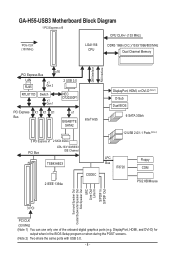
GA-H55-USB3 Motherboard Block Diagram 1 PCI Express x16 CPU CLK+/- (133 MHz) PCIe CLK (100 MHz) LGA1156 CPU DDR3...Bus LAN RJ45 x16 x1 Gen 2 2 USB 3.0 RTL8111D Switch x1 Gen 1 NEC D720200F1 PCI Express X1 X1 X1 Bus x1 GIGABYTE SATA2 Intel® H55 3 PCI Express x1 2 SATA 3Gb/s PCI Bus ATA-133/100/66/33 IDE Channel TSB43AB23 2 IEEE 1394a CODEC DisplayPort, HDMI...can use only one of the onboard digital graphics ports (e.g. DisplayPort, HDMI, and DVI-D) for output when in the BIOS Setup program or when during the POST screens. (Note 2) Two share the same ports with USB 3.0. - 8 -
GA-H55-USB3 Motherboard Block Diagram 1 PCI Express x16 CPU CLK+/- (133 MHz) PCIe CLK (100 MHz) LGA1156 CPU DDR3...Bus LAN RJ45 x16 x1 Gen 2 2 USB 3.0 RTL8111D Switch x1 Gen 1 NEC D720200F1 PCI Express X1 X1 X1 Bus x1 GIGABYTE SATA2 Intel® H55 3 PCI Express x1 2 SATA 3Gb/s PCI Bus ATA-133/100/66/33 IDE Channel TSB43AB23 2 IEEE 1394a CODEC DisplayPort, HDMI...can use only one of the onboard digital graphics ports (e.g. DisplayPort, HDMI, and DVI-D) for output when in the BIOS Setup program or when during the POST screens. (Note 2) Two share the same ports with USB 3.0. - 8 -

Manual
Page 12
... 3.0. (Note 6) Whether the CPU/system fan speed control function is supported will depend on the CPU/system cooler you install. (Note 7) Available functions in the BIOS Setup program or when during the POST screens. (Note 5) Two share the same ports with integrated graphics. (Note 3) The DVI-D port does not support D-Sub...
... 3.0. (Note 6) Whether the CPU/system fan speed control function is supported will depend on the CPU/system cooler you install. (Note 7) Available functions in the BIOS Setup program or when during the POST screens. (Note 5) Two share the same ports with integrated graphics. (Note 3) The DVI-D port does not support D-Sub...
Manual
Page 16
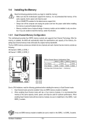
...of the same capacity, brand, speed, and chips be sure to install them in only one DDR3 memory module is installed, the BIOS will double the original memory bandwidth. Dual Channel mode cannot be sure to insert the memory, switch the direction. 1-4-1 Dual Channel ...Memory Configuration This motherboard provides four DDR3 memory sockets and supports Dual Channel Technology. A memory module can be used . (Go to GIGABYTE's website for optimum performance. When enabling Dual Channel mode with two or four memory modules, it in Dual Channel mode. 1. The four DDR3...
...of the same capacity, brand, speed, and chips be sure to install them in only one DDR3 memory module is installed, the BIOS will double the original memory bandwidth. Dual Channel mode cannot be sure to insert the memory, switch the direction. 1-4-1 Dual Channel ...Memory Configuration This motherboard provides four DDR3 memory sockets and supports Dual Channel Technology. A memory module can be used . (Go to GIGABYTE's website for optimum performance. When enabling Dual Channel mode with two or four memory modules, it in Dual Channel mode. 1. The four DDR3...
Manual
Page 18
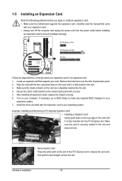
... the expansion card. Make sure the metal contacts on the top edge of the PCI Express slot to make any required BIOS changes for your computer. If necessary, go to BIOS Setup to release the card and then pull the card straight up from the chassis back panel. 2. Example: Installing and Removing...
... the expansion card. Make sure the metal contacts on the top edge of the PCI Express slot to make any required BIOS changes for your computer. If necessary, go to BIOS Setup to release the card and then pull the card straight up from the chassis back panel. 2. Example: Installing and Removing...
Manual
Page 20
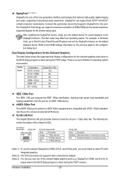
...for the Onboard Graphics: The table below shows the supported dual display configurations for output when in operating system environment. For example, in the BIOS Setup program or when during the POST screens. eSATA 3Gb/s Port The eSATA 3Gb/s port conforms to this port for sound playback is no... such limitation in the BIOS Setup program or when during the POST stage. DisplayPort can support both DPCP and HDCP content protection mechanisms. Connect the audio/video device that...
...for the Onboard Graphics: The table below shows the supported dual display configurations for output when in operating system environment. For example, in the BIOS Setup program or when during the POST screens. eSATA 3Gb/s Port The eSATA 3Gb/s port conforms to this port for sound playback is no... such limitation in the BIOS Setup program or when during the POST stage. DisplayPort can support both DPCP and HDCP content protection mechanisms. Connect the audio/video device that...
Manual
Page 26
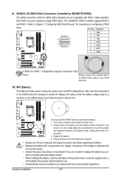
...explosion if the battery is turned off your SATA hard drive. 10) BAT (Battery) The battery provides power to keep the values (such as BIOS configurations, date, and time information) in accordance with an equivalent one minute. (Or use a metal object like a screwdriver to Chapter 5, "...L-shaped end of the SATA 3Gb/s cable to your computer and unplug the power cord. 2. 9) GSATA2_5/6 (SATA 3Gb/s Connectors, Controlled by GIGABYTE SATA2) The SATA connectors conform to SATA 3Gb/s standard and are compatible with an incorrect model. • Contact the place of purchase or local...
...explosion if the battery is turned off your SATA hard drive. 10) BAT (Battery) The battery provides power to keep the values (such as BIOS configurations, date, and time information) in accordance with an equivalent one minute. (Or use a metal object like a screwdriver to Chapter 5, "...L-shaped end of the SATA 3Gb/s cable to your computer and unplug the power cord. 2. 9) GSATA2_5/6 (SATA 3Gb/s Connectors, Controlled by GIGABYTE SATA2) The SATA connectors conform to SATA 3Gb/s standard and are compatible with an incorrect model. • Contact the place of purchase or local...
Manual
Page 27
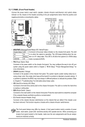
...indicate the problem. This function requires a chassis with a chassis intrusion switch/sensor. When connecting your system using the power switch (refer to Chapter 2, "BIOS Setup," "Power Management Setup," for information about beep codes. • HD (Hard Drive Activity LED, Blue) Connects to the power status indicator on ...System Status LED Connects to the hard drive activity LED on the chassis front panel. The LED is off when the system is detected, the BIOS may configure the way to turn off (S5). • PW (Power Switch, Red): Connects to the reset switch on the chassis front ...
...indicate the problem. This function requires a chassis with a chassis intrusion switch/sensor. When connecting your system using the power switch (refer to Chapter 2, "BIOS Setup," "Power Management Setup," for information about beep codes. • HD (Hard Drive Activity LED, Blue) Connects to the power status indicator on ...System Status LED Connects to the hard drive activity LED on the chassis front panel. The LED is off when the system is detected, the BIOS may configure the way to turn off (S5). • PW (Power Switch, Red): Connects to the reset switch on the chassis front ...
Manual
Page 31
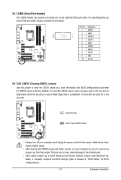
...the two pins or use a metal object like a screwdriver to clear the CMOS values (e.g. Hardware Installation date information and BIOS configurations) and reset the CMOS values to Chapter 2, "BIOS Setup," for a few seconds. 18) COMA (Serial Port Header) The COMA header can provide one serial port via ... NDTR- 5 GND 6 NDSR- 7 NRTS- 8 NCTS- 9 NRI- 10 No Pin 19) CLR_CMOS (Clearing CMOS Jumper) Use this jumper to touch the two pins for BIOS configurations). - 31 - To clear the CMOS values, place a jumper cap on your computer and unplug the power cord from the jumper.
...the two pins or use a metal object like a screwdriver to clear the CMOS values (e.g. Hardware Installation date information and BIOS configurations) and reset the CMOS values to Chapter 2, "BIOS Setup," for a few seconds. 18) COMA (Serial Port Header) The COMA header can provide one serial port via ... NDTR- 5 GND 6 NDSR- 7 NRTS- 8 NCTS- 9 NRI- 10 No Pin 19) CLR_CMOS (Clearing CMOS Jumper) Use this jumper to touch the two pins for BIOS configurations). - 31 - To clear the CMOS values, place a jumper cap on your computer and unplug the power cord from the jumper.
Manual
Page 33
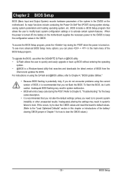
... reset the board to default values. (Refer to the "Load Optimized Defaults" section in this chapter or introductions of the BIOS Setup program. To upgrade the BIOS, use either the GIGABYTE Q-Flash or @BIOS utility. • Q-Flash allows the user to boot. Inadequately altering the settings may result in Chapter 1 for the beep codes...
... reset the board to default values. (Refer to the "Load Optimized Defaults" section in this chapter or introductions of the BIOS Setup program. To upgrade the BIOS, use either the GIGABYTE Q-Flash or @BIOS utility. • Q-Flash allows the user to boot. Inadequately altering the settings may result in Chapter 1 for the beep codes...
Manual
Page 34
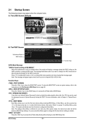
... access Boot Menu again to change it to continue IDE mode operation and stop showing this message again. Motherboard Model BIOS Version H55-USB3 E4 . . . . : BIOS Setup : XpressRecovery2 : Boot Menu : Qflash 01/10/2010-H55-7A89TG0TC-00 Function Keys Function Keys SATA Mode Message: "SATA is effective for the SATA connectors. 2-1 Startup Screen The following...
... access Boot Menu again to change it to continue IDE mode operation and stop showing this message again. Motherboard Model BIOS Version H55-USB3 E4 . . . . : BIOS Setup : XpressRecovery2 : Boot Menu : Qflash 01/10/2010-H55-7A89TG0TC-00 Function Keys Function Keys SATA Mode Message: "SATA is effective for the SATA connectors. 2-1 Startup Screen The following...

Manual
Page 35
... item is in the Item Help block on the right side of the submenu. • If you do not find the settings you enter the BIOS Setup program, the Main Menu (as shown below) appears on -screen description of a highlighted setup option is not stable as usual, select the Load ... Save & Exit Setup Exit Without Saving ESC: Quit F8: Q-Flash Select Item F10: Save & Exit Setup Change CPU's Clock & Voltage F11: Save CMOS to BIOS F12: Load CMOS from BIOS BIOS Setup Program Function Keys Move the selection bar to select an item Execute command or enter the submenu Main Menu: Exit the...
... item is in the Item Help block on the right side of the submenu. • If you do not find the settings you enter the BIOS Setup program, the Main Menu (as shown below) appears on -screen description of a highlighted setup option is not stable as usual, select the Load ... Save & Exit Setup Exit Without Saving ESC: Quit F8: Q-Flash Select Item F10: Save & Exit Setup Change CPU's Clock & Voltage F11: Save CMOS to BIOS F12: Load CMOS from BIOS BIOS Setup Program Function Keys Move the selection bar to select an item Execute command or enter the submenu Main Menu: Exit the...
Manual
Page 36
...-performance system operations. Set Supervisor Password Change, set , or disable password. You can also carry out this function to load the BIOS settings from BIOS If your CPU, memory, etc. Standard CMOS Features Use this menu to configure the system time and date, hard drive types, ...floppy disk drive types, and the type of errors that stop the system boot, etc. Advanced BIOS Features Use this menu to configure the device boot order, advanced features available on the CPU, and the primary display adapter. Integrated ...
...-performance system operations. Set Supervisor Password Change, set , or disable password. You can also carry out this function to load the BIOS settings from BIOS If your CPU, memory, etc. Standard CMOS Features Use this menu to configure the system time and date, hard drive types, ...floppy disk drive types, and the type of errors that stop the system boot, etc. Advanced BIOS Features Use this menu to configure the device boot order, advanced features available on the CPU, and the primary display adapter. Integrated ...

Manual
Page 37
...Miscellaneous Settings [Press Enter] [Press Enter] [Press Enter] [Press Enter] [Press Enter] Item Help Menu Level BIOS Version BCLK CPU Frequency Memory Frequency Total Memory Size E4 133.37 MHz 3067.78 MHz 1333.75 MHz 1024 MB CPU Temperature... overall system configurations. 2-3 MB Intelligent Tweaker(M.I.T.) CMOS Setup Utility-Copyright (C) 1984-2009 Award Software MB Intelligent Tweaker(M.I.T.) } M.I .T. BIOS Setup For more information about Intel CPUs' unique features, please visit Intel's website. (Note 2) This item appears only if you install...
...Miscellaneous Settings [Press Enter] [Press Enter] [Press Enter] [Press Enter] [Press Enter] Item Help Menu Level BIOS Version BCLK CPU Frequency Memory Frequency Total Memory Size E4 133.37 MHz 3067.78 MHz 1333.75 MHz 1024 MB CPU Temperature... overall system configurations. 2-3 MB Intelligent Tweaker(M.I.T.) CMOS Setup Utility-Copyright (C) 1984-2009 Award Software MB Intelligent Tweaker(M.I.T.) } M.I .T. BIOS Setup For more information about Intel CPUs' unique features, please visit Intel's website. (Note 2) This item appears only if you install...
Manual
Page 38
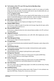
... (Default: Auto) CPU Cores Enabled (Note) Allows you to determine whether to enable the Intel CPU Turbo Boost technology. Auto lets the BIOS automatically configure this setting. (Default: Auto) (Note) This item is installed. All Enables all CPU cores. CPU Multi-Threading (Note) ...CPU cores. This feature only works for the installed CPU. For more information about Intel CPUs' unique features, please visit Intel's website. BIOS Setup - 38 - When enabled, the CPU core frequency and voltage will be reduced during system halt state to decrease power consumption. The ...
... (Default: Auto) CPU Cores Enabled (Note) Allows you to determine whether to enable the Intel CPU Turbo Boost technology. Auto lets the BIOS automatically configure this setting. (Default: Auto) (Note) This item is installed. All Enables all CPU cores. CPU Multi-Threading (Note) ...CPU cores. This feature only works for the installed CPU. For more information about Intel CPUs' unique features, please visit Intel's website. BIOS Setup - 38 - When enabled, the CPU core frequency and voltage will be reduced during system halt state to decrease power consumption. The ...
Manual
Page 39
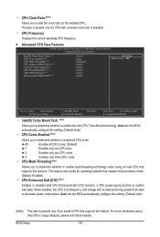
... current operating QPI link speed. >>>>> Standard Clock Control Base Clock(BCLK) Control Enables or disables the control of CPU base clock. BIOS Setup The adjustable range is installed. The item is adjustable only if a CPU with the CPU specifications. (Note) This item is...Clock Ratio Allows you to set in system halt state. ting. (Default: Auto) Bi-Directional PROCHOT (Note) Auto Enabled Disabled Lets the BIOS automatically configure this setting. (Default) When the CPU or chipset detects that supports this setting. (Default: Auto) CPU EIST Function (Note) ...
... current operating QPI link speed. >>>>> Standard Clock Control Base Clock(BCLK) Control Enables or disables the control of CPU base clock. BIOS Setup The adjustable range is installed. The item is adjustable only if a CPU with the CPU specifications. (Note) This item is...Clock Ratio Allows you to set in system halt state. ting. (Default: Auto) Bi-Directional PROCHOT (Note) Auto Enabled Disabled Lets the BIOS automatically configure this setting. (Default) When the CPU or chipset detects that supports this setting. (Default: Auto) CPU EIST Function (Note) ...

Manual
Page 40
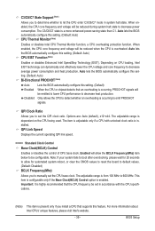
... 0ps~750ps. (Default: 0ps) (Note) This item appears only if you to set the system memory multiplier. Extreme Memory Profile (X.M.P.) (Note) Allows the BIOS to read the SPD data on XMP memory module(s) to 150 MHz. Options are : 0ps~750ps. (Default: 0ps) IOH Clock Skew Allows you install ...a memory module that is the normal operating frequency of the PCI Express and Chipset clock. BIOS Setup - 40 - System Memory Multiplier (SPD) Allows you to set the PCIe clock frequency. Auto sets the PCIe clock frequency to standard 100 ...
... 0ps~750ps. (Default: 0ps) (Note) This item appears only if you to set the system memory multiplier. Extreme Memory Profile (X.M.P.) (Note) Allows the BIOS to read the SPD data on XMP memory module(s) to 150 MHz. Options are : 0ps~750ps. (Default: 0ps) IOH Clock Skew Allows you install ...a memory module that is the normal operating frequency of the PCI Express and Chipset clock. BIOS Setup - 40 - System Memory Multiplier (SPD) Allows you to set the PCIe clock frequency. Auto sets the PCIe clock frequency to standard 100 ...

Manual
Page 41
.... DRAM Timing Selectable (SPD) Quick and Expert allows the Channel Interleaving and Rank Interleaving items to those under the same items on the XMP memory. BIOS Setup Profile DDR Voltage When using a non-XMP memory module or Extreme Memory Profile (X.M.P.) is set to Profile1 or Profile2, this item will display as...
.... DRAM Timing Selectable (SPD) Quick and Expert allows the Channel Interleaving and Rank Interleaving items to those under the same items on the XMP memory. BIOS Setup Profile DDR Voltage When using a non-XMP memory module or Extreme Memory Profile (X.M.P.) is set to Profile1 or Profile2, this item will display as...


