Manual
Page 1
GA-H55-USB3 LGA1156 socket motherboard for Intel® Core™ i7 processor family/ Intel® Core™ i5 processor family/ Intel® Core™ i3 processor family User's Manual Rev. 1001 12ME-H55USB3-1001R
GA-H55-USB3 LGA1156 socket motherboard for Intel® Core™ i7 processor family/ Intel® Core™ i5 processor family/ Intel® Core™ i3 processor family User's Manual Rev. 1001 12ME-H55USB3-1001R
Manual
Page 2
Motherboard GA-H55-USB3 Feb. 5, 2010 Motherboard GA-H55-USB3 Feb. 5, 2010
Motherboard GA-H55-USB3 Feb. 5, 2010 Motherboard GA-H55-USB3 Feb. 5, 2010
Manual
Page 3
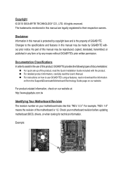
...or download the information on/from the Support&Downloads\Motherboard\Technology Guide page on your motherboard revision before updating motherboard BIOS, drivers, or when looking for technical information. Example: Disclaimer Information in the use GIGABYTE's unique features, read the User's Manual. No...CO., LTD. For product-related information, check on our website at: http://www.gigabyte.com.tw Identifying Your Motherboard Revision The revision number on our website. Check your motherboard looks like this manual are legally registered to use of this manual may be ...
...or download the information on/from the Support&Downloads\Motherboard\Technology Guide page on your motherboard revision before updating motherboard BIOS, drivers, or when looking for technical information. Example: Disclaimer Information in the use GIGABYTE's unique features, read the User's Manual. No...CO., LTD. For product-related information, check on our website at: http://www.gigabyte.com.tw Identifying Your Motherboard Revision The revision number on our website. Check your motherboard looks like this manual are legally registered to use of this manual may be ...
Manual
Page 4
Table of Contents Box Contents...6 Optional Items...6 GA-H55-USB3 Motherboard Layout 7 GA-H55-USB3 Motherboard Block Diagram 8 Chapter 1 Hardware Installation 9 1-1 Installation Precautions 9 1-2 Product Specifications 10 1-3 Installing the CPU and CPU Cooler 13 1-3-1 Installing the CPU 13 1-3-2 Installing the CPU Cooler ...
Table of Contents Box Contents...6 Optional Items...6 GA-H55-USB3 Motherboard Layout 7 GA-H55-USB3 Motherboard Block Diagram 8 Chapter 1 Hardware Installation 9 1-1 Installation Precautions 9 1-2 Product Specifications 10 1-3 Installing the CPU and CPU Cooler 13 1-3-1 Installing the CPU 13 1-3-2 Installing the CPU Cooler ...
Manual
Page 6
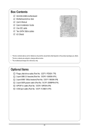
...-1IE008-0*R) 2-port SATA power cable (Part No. 12CF1-2SERPW-0*R) S/PDIF In cable (Part No. 12CR1-1SPDIN-0*R) COM port cable (Part No. 12CF1-1CM001-3*R) - 6 - Box Contents GA-H55-USB3 motherboard Motherboard driver disk User's Manual Quick Installation Guide One IDE cable Two SATA 3Gb/s cables I/O Shield • The box contents above are subject to change without...
...-1IE008-0*R) 2-port SATA power cable (Part No. 12CF1-2SERPW-0*R) S/PDIF In cable (Part No. 12CR1-1SPDIN-0*R) COM port cable (Part No. 12CF1-1CM001-3*R) - 6 - Box Contents GA-H55-USB3 motherboard Motherboard driver disk User's Manual Quick Installation Guide One IDE cable Two SATA 3Gb/s cables I/O Shield • The box contents above are subject to change without...
Manual
Page 7
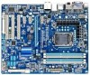
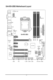
GA-H55-USB3 Motherboard Layout KB_USB CPU_FAN VGA_DVI ATX_12V_2X4 LGA1156 PHASE LED DP_HDMI_SPDIF ESATA_1394_USB USB30_LAN NEC D720200F1 AUDIO F_AUDIO PCIEX1_1 RTL8111D PCIEX16 PCIEX1_2 PCI2 CODEC PCIEX1_3 SPDIF_O CD_IN PCI1 SPDIF_I PCI2 IT8720 PCI3 ATX PWR_FAN GA-H55-USB3 DDR3_2 DDR3_1 DDR3_4 DDR3_3 GIGABYTE SATA2 GSATA2_6 GSATA2_5 BAT Intel® H55 M_BIOS B_BIOS SYS_FAN2 TSB43AB23 F_1394 SATA2_3 SATA2_0 SATA2_4 SATA2_1 SATA2_2 CLR_CMOS IDE COMA FDD F_USB1 F_USB2 F_USB3 SYS_FAN1 F_PANEL - 7 -
GA-H55-USB3 Motherboard Layout KB_USB CPU_FAN VGA_DVI ATX_12V_2X4 LGA1156 PHASE LED DP_HDMI_SPDIF ESATA_1394_USB USB30_LAN NEC D720200F1 AUDIO F_AUDIO PCIEX1_1 RTL8111D PCIEX16 PCIEX1_2 PCI2 CODEC PCIEX1_3 SPDIF_O CD_IN PCI1 SPDIF_I PCI2 IT8720 PCI3 ATX PWR_FAN GA-H55-USB3 DDR3_2 DDR3_1 DDR3_4 DDR3_3 GIGABYTE SATA2 GSATA2_6 GSATA2_5 BAT Intel® H55 M_BIOS B_BIOS SYS_FAN2 TSB43AB23 F_1394 SATA2_3 SATA2_0 SATA2_4 SATA2_1 SATA2_2 CLR_CMOS IDE COMA FDD F_USB1 F_USB2 F_USB3 SYS_FAN1 F_PANEL - 7 -
Manual
Page 8
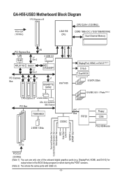
...GA-H55-USB3 Motherboard Block Diagram 1 PCI Express x16 CPU CLK+/- (133 MHz) PCIe CLK (100 MHz) LGA1156 CPU DDR3 1666 (O.C.)/1333/1066/800 MHz Dual Channel Memory DMI Interface FDI Interface PCI Express Bus LAN RJ45 x16 x1 Gen 2 2 USB 3.0 RTL8111D Switch x1 Gen 1 NEC D720200F1 PCI Express X1 X1 X1 Bus x1 GIGABYTE... SATA2 Intel® H55 3 PCI Express x1 2 SATA 3Gb/s PCI Bus ATA-133/100/66/33 IDE Channel TSB43AB23 2 IEEE 1394a CODEC DisplayPort, HDMI, ...
...GA-H55-USB3 Motherboard Block Diagram 1 PCI Express x16 CPU CLK+/- (133 MHz) PCIe CLK (100 MHz) LGA1156 CPU DDR3 1666 (O.C.)/1333/1066/800 MHz Dual Channel Memory DMI Interface FDI Interface PCI Express Bus LAN RJ45 x16 x1 Gen 2 2 USB 3.0 RTL8111D Switch x1 Gen 1 NEC D720200F1 PCI Express X1 X1 X1 Bus x1 GIGABYTE... SATA2 Intel® H55 3 PCI Express x1 2 SATA 3Gb/s PCI Bus ATA-133/100/66/33 IDE Channel TSB43AB23 2 IEEE 1394a CODEC DisplayPort, HDMI, ...

Manual
Page 9
...or within an electrostatic shielding container. • Before unplugging the power supply cable from the power outlet before installing or removing the motherboard or other hardware components. • When connecting hardware components to the internal connectors on the computer power during the installation process ... product, please verify that all cables and power connectors of your hardware components are no leftover screws or metal components placed on the motherboard or within the computer casing. • Do not place the computer system on an uneven surface. • Do not place the...
...or within an electrostatic shielding container. • Before unplugging the power supply cable from the power outlet before installing or removing the motherboard or other hardware components. • When connecting hardware components to the internal connectors on the computer power during the installation process ... product, please verify that all cables and power connectors of your hardware components are no leftover screws or metal components placed on the motherboard or within the computer casing. • Do not place the computer system on an uneven surface. • Do not place the...

Manual
Page 12
... function is installed, the actual memory size displayed will depend on the CPU/system cooler you install. (Note 7) Available functions in EasyTune may differ by motherboard model. DisplayPort, HDMI, and DVI-D) for Microsoft® Windows® 7/Vista/XP Form Factor w ATX Form Factor; 30.5cm x 24.4cm (Note 1) Due to Windows...
... function is installed, the actual memory size displayed will depend on the CPU/system cooler you install. (Note 7) Available functions in EasyTune may differ by motherboard model. DisplayPort, HDMI, and DVI-D) for Microsoft® Windows® 7/Vista/XP Form Factor w ATX Form Factor; 30.5cm x 24.4cm (Note 1) Due to Windows...
Manual
Page 13
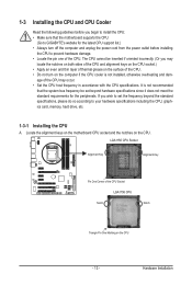
...system bus frequency be inserted if oriented incorrectly. (Or you begin to install the CPU: • Make sure that the motherboard supports the CPU. (Go to GIGABYTE's website for the peripherals. LGA1156 CPU Socket Alignment Key Alignment Key Pin One Corner of the CPU Socket LGA1156 CPU Notch ...Notch Triangle Pin One Marking on the CPU. Locate the alignment keys on the motherboard CPU socket and the notches on the CPU - 13...
...system bus frequency be inserted if oriented incorrectly. (Or you begin to install the CPU: • Make sure that the motherboard supports the CPU. (Go to GIGABYTE's website for the peripherals. LGA1156 CPU Socket Alignment Key Alignment Key Pin One Corner of the CPU Socket LGA1156 CPU Notch ...Notch Triangle Pin One Marking on the CPU. Locate the alignment keys on the motherboard CPU socket and the notches on the CPU - 13...

Manual
Page 14
... socket (or you may align the CPU notches with your thumb to lift up the front edge (next to correctly install the CPU into the motherboard CPU socket. NOTE: Hold the CPU socket lever by the handle, not the lever base portion. Step 5: Push the CPU socket lever back into position...
... socket (or you may align the CPU notches with your thumb to lift up the front edge (next to correctly install the CPU into the motherboard CPU socket. NOTE: Hold the CPU socket lever by the handle, not the lever base portion. Step 5: Push the CPU socket lever back into position...

Manual
Page 15
...Step 4: You should hear a "click" when pushing down on installing the cooler.) Step 5: After the installation, check the back of the motherboard. Hardware Installation Check that the Male and Female push pins are joined closely. (Refer to your CPU cooler installation manual for instructions on the ...cooler, on the contrary, is complete. 1-3-2 Installing the CPU Cooler Follow the steps below to correctly install the CPU cooler on the motherboard. (The following procedure uses Intel® boxed cooler as the picture above shows, the installation is to install.) Step 3: Place the...
...Step 4: You should hear a "click" when pushing down on installing the cooler.) Step 5: After the installation, check the back of the motherboard. Hardware Installation Check that the Male and Female push pins are joined closely. (Refer to your CPU cooler installation manual for instructions on the ...cooler, on the contrary, is complete. 1-3-2 Installing the CPU Cooler Follow the steps below to correctly install the CPU cooler on the motherboard. (The following procedure uses Intel® boxed cooler as the picture above shows, the installation is to install.) Step 3: Place the...
Manual
Page 16
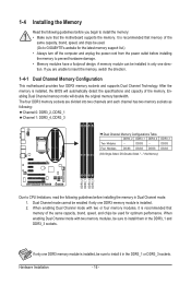
...guidelines before installing the memory to prevent hardware damage. • Memory modules have a foolproof design. It is installed, be sure to GIGABYTE's website for optimum performance. DS/SS - - Dual Channel mode cannot be installed in only one DDR3 memory module is recommended that...Dual Channel mode with two memory modules, be sure to insert the memory, switch the direction. 1-4-1 Dual Channel Memory Configuration This motherboard provides four DDR3 memory sockets and supports Dual Channel Technology. When enabling Dual Channel mode with two or four memory modules, it in...
...guidelines before installing the memory to prevent hardware damage. • Memory modules have a foolproof design. It is installed, be sure to GIGABYTE's website for optimum performance. DS/SS - - Dual Channel mode cannot be installed in only one DDR3 memory module is recommended that...Dual Channel mode with two memory modules, be sure to insert the memory, switch the direction. 1-4-1 Dual Channel Memory Configuration This motherboard provides four DDR3 memory sockets and supports Dual Channel Technology. When enabling Dual Channel mode with two or four memory modules, it in...
Manual
Page 17
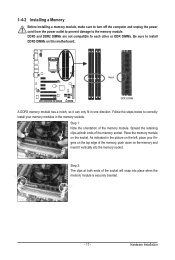
..., make sure to turn off the computer and unplug the power cord from the power outlet to prevent damage to install DDR3 DIMMs on this motherboard. DDR3 and DDR2 DIMMs are not compatible to each other or DDR DIMMs. Be sure to the memory module. Notch DDR3 DIMM A DDR3 memory module...
..., make sure to turn off the computer and unplug the power cord from the power outlet to prevent damage to install DDR3 DIMMs on this motherboard. DDR3 and DDR2 DIMMs are not compatible to each other or DDR DIMMs. Be sure to the memory module. Notch DDR3 DIMM A DDR3 memory module...
Manual
Page 18
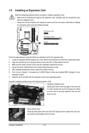
... PCI Express slot to prevent hardware damage. Hardware Installation - 18 - If necessary, go to BIOS Setup to install an expansion card: • Make sure the motherboard supports the expansion card.
... PCI Express slot to prevent hardware damage. Hardware Installation - 18 - If necessary, go to BIOS Setup to install an expansion card: • Make sure the motherboard supports the expansion card.

Manual
Page 21
... connect side speakers in devices such as a USB keyboard/mouse, USB printer, USB flash drive and etc. Do not rock it straight out from the motherboard. • When removing the cable, pull it side to side to connect rear speakers in Chapter 5, "Configuring 2/4/5.1/7.1-Channel Audio." • When removing the cable connected...
... connect side speakers in devices such as a USB keyboard/mouse, USB printer, USB flash drive and etc. Do not rock it straight out from the motherboard. • When removing the cable, pull it side to side to connect rear speakers in Chapter 5, "Configuring 2/4/5.1/7.1-Channel Audio." • When removing the cable connected...

Manual
Page 22
..., make sure your devices are compliant with the connectors you wish to connect. • Before installing the devices, be sure to the connector on the motherboard. Unplug the power cord from the power outlet to prevent damage to the devices. • After installing the device and before connecting external devices: •...
..., make sure your devices are compliant with the connectors you wish to connect. • Before installing the devices, be sure to the connector on the motherboard. Unplug the power cord from the power outlet to prevent damage to the devices. • After installing the device and before connecting external devices: •...

Manual
Page 23
... CPU manufacturer when using an Intel Extreme Edition CPU (130W). • To meet expansion requirements, it is turned off and all the components on the motherboard. The power connector possesses a foolproof design.
... CPU manufacturer when using an Intel Extreme Edition CPU (130W). • To meet expansion requirements, it is turned off and all the components on the motherboard. The power connector possesses a foolproof design.

Manual
Page 24
The motherboard supports CPU fan speed control, which requires the use of the cable is used to prevent your CPU and system from overheating. For optimum heat ...). For purchasing the optional floppy disk drive cable, please contact the local dealer. 33 1 34 2 Hardware Installation - 24 - 3/4/5) CPU_FAN/SYS_FAN1/SYS_FAN2/PWR_FAN (Fan Headers) The motherboard has a 4-pin CPU fan header (CPU_FAN), a 4-pin (SYS_FAN2) and a 3-pin system fans, and a 3-pin power fan. Definition 1 GND 2 +12V 3 Sense • Be sure to connect...
The motherboard supports CPU fan speed control, which requires the use of the cable is used to prevent your CPU and system from overheating. For optimum heat ...). For purchasing the optional floppy disk drive cable, please contact the local dealer. 33 1 34 2 Hardware Installation - 24 - 3/4/5) CPU_FAN/SYS_FAN1/SYS_FAN2/PWR_FAN (Fan Headers) The motherboard has a 4-pin CPU fan header (CPU_FAN), a 4-pin (SYS_FAN2) and a 3-pin system fans, and a 3-pin power fan. Definition 1 GND 2 +12V 3 Sense • Be sure to connect...

Manual
Page 28
... the wire assignments of the module connector match the pin assignments of a single plug. Incorrect connection between the module connector and the motherboard header will be present on how to activate AC'97 functionality via the audio software in Chapter 5, "Configuring 2/4/5.1/7.1-Channel Audio." •... of the front and back panel audio connections simultaneously. You may connect the audio cable that has separated connectors on each wire instead of the motherboard header. For HD Front Panel Audio: For AC'97 Front Panel Audio: Pin No. Definition 1 1 CD-L 2 GND 3 GND 4 CD-R...
... the wire assignments of the module connector match the pin assignments of a single plug. Incorrect connection between the module connector and the motherboard header will be present on how to activate AC'97 functionality via the audio software in Chapter 5, "Configuring 2/4/5.1/7.1-Channel Audio." •... of the front and back panel audio connections simultaneously. You may connect the audio cable that has separated connectors on each wire instead of the motherboard header. For HD Front Panel Audio: For AC'97 Front Panel Audio: Pin No. Definition 1 1 CD-L 2 GND 3 GND 4 CD-R...


