Manual
Page 3
... on/from the Support&Downloads\Motherboard\Technology Guide page on our website. Disclaimer Information in the use GIGABYTE's unique features, read the User's Manual. Documentation Classifications In order to the specifications and features in any means without prior notice. For example, "REV: 1.0" means the revision of this product, GIGABYTE provides the following types of documentations: For quick set-up of GIGABYTE. For product-related...
... on/from the Support&Downloads\Motherboard\Technology Guide page on our website. Disclaimer Information in the use GIGABYTE's unique features, read the User's Manual. Documentation Classifications In order to the specifications and features in any means without prior notice. For example, "REV: 1.0" means the revision of this product, GIGABYTE provides the following types of documentations: For quick set-up of GIGABYTE. For product-related...
Manual
Page 4
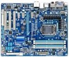
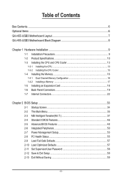
...Contents Box Contents...6 Optional Items...6 GA-H55-USB3 Motherboard Layout 7 GA-H55-USB3 Motherboard Block Diagram 8 Chapter 1 Hardware Installation 9 1-1 Installation Precautions 9 1-2 Product Specifications 10 1-3 Installing the CPU and CPU Cooler 13 1-3-1 Installing the CPU 13 1-3-2 Installing the CPU Cooler 15 1-4 Installing the Memory 16 1-4-1 Dual Channel Memory Configuration 16 1-4-2 Installing a Memory 17 1-5 Installing an Expansion Card 18 1-6 Back Panel Connectors 19 1-7 Internal Connectors 22 Chapter 2 BIOS Setup 33 2-1 Startup Screen 34 2-2 The Main Menu 35 2-3 MB...
...Contents Box Contents...6 Optional Items...6 GA-H55-USB3 Motherboard Layout 7 GA-H55-USB3 Motherboard Block Diagram 8 Chapter 1 Hardware Installation 9 1-1 Installation Precautions 9 1-2 Product Specifications 10 1-3 Installing the CPU and CPU Cooler 13 1-3-1 Installing the CPU 13 1-3-2 Installing the CPU Cooler 15 1-4 Installing the Memory 16 1-4-1 Dual Channel Memory Configuration 16 1-4-2 Installing a Memory 17 1-5 Installing an Expansion Card 18 1-6 Back Panel Connectors 19 1-7 Internal Connectors 22 Chapter 2 BIOS Setup 33 2-1 Startup Screen 34 2-2 The Main Menu 35 2-3 MB...
Manual
Page 10
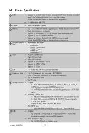
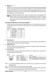
... the latest memory support list.) Integrated in the Chipset: - 1 x D-Sub port - 1 x DVI-D port (Note 3) (Note 4) - 1 x HDMI port (Note 4) - 1 x DisplayPort (Note 4) Realtek ALC889 codec High Definition Audio 2/4/5.1/7.1-channel Support for Dolby® Home Theater Support for S/PDIF In/Out Support for SATA RAID 0, RAID 1, and JBOD w iTE IT8720 chip: - 1 x floppy disk drive connector supporting up to 2 SATA 3Gb/s devices - Support for CD In LAN 1 x Realtek RTL8111D chip (10/100/1000 Mbit) Expansion Slots 1 x PCI Express x16 slot, running...
... the latest memory support list.) Integrated in the Chipset: - 1 x D-Sub port - 1 x DVI-D port (Note 3) (Note 4) - 1 x HDMI port (Note 4) - 1 x DisplayPort (Note 4) Realtek ALC889 codec High Definition Audio 2/4/5.1/7.1-channel Support for Dolby® Home Theater Support for S/PDIF In/Out Support for SATA RAID 0, RAID 1, and JBOD w iTE IT8720 chip: - 1 x floppy disk drive connector supporting up to 2 SATA 3Gb/s devices - Support for CD In LAN 1 x Realtek RTL8111D chip (10/100/1000 Mbit) Expansion Slots 1 x PCI Express x16 slot, running...
Manual
Page 20
... up to SATA 3Gb/s standard and is compatible with integrated graphics. (Note 2) The DVI-D port does not support D-Sub connection by adapter. (Note 3) You can use the onboard DisplayPort, HDMI, DVI-D, and D-Sub ports, you must install an Intel CPU with SATA 1.5Gb/s standard. DisplayPort, HDMI, and DVI-D) for sound playback is no such limitation in the BIOS Setup program or when during the POST screens. Connection/ Speed LED Activity LED LAN Port Connection/Speed LED: State Description...
... up to SATA 3Gb/s standard and is compatible with integrated graphics. (Note 2) The DVI-D port does not support D-Sub connection by adapter. (Note 3) You can use the onboard DisplayPort, HDMI, DVI-D, and D-Sub ports, you must install an Intel CPU with SATA 1.5Gb/s standard. DisplayPort, HDMI, and DVI-D) for sound playback is no such limitation in the BIOS Setup program or when during the POST screens. Connection/ Speed LED Activity LED LAN Port Connection/Speed LED: State Description...
Manual
Page 31
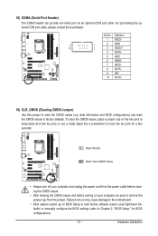
... motherboard. • After system restart, go to BIOS Setup to load factory defaults (select Load Optimized Defaults) or manually configure the BIOS settings (refer to remove the jumper cap from the power outlet before clearing the CMOS values. • After clearing the CMOS values and before turning on the two pins to temporarily short the two pins or use a metal object like a screwdriver to touch the two pins for BIOS configurations). - 31 - For purchasing the optional COM port cable...
... motherboard. • After system restart, go to BIOS Setup to load factory defaults (select Load Optimized Defaults) or manually configure the BIOS settings (refer to remove the jumper cap from the power outlet before clearing the CMOS values. • After clearing the CMOS values and before turning on the two pins to temporarily short the two pins or use a metal object like a screwdriver to touch the two pins for BIOS configurations). - 31 - For purchasing the optional COM port cable...
Manual
Page 34
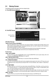
... want to change the first boot device setting as needed. : Q-FLASH Press the key to access the Q-Flash utility directly without entering BIOS Setup. The LOGO Screen (Default) B. Motherboard Model BIOS Version H55-USB3 E4 . . . . : BIOS Setup : XpressRecovery2 : Boot Menu : Qflash 01/10/2010-H55-7A89TG0TC-00 Function Keys Function Keys SATA Mode Message: "SATA is effective for the SATA connectors. The message that follows asks if you to set to its default values, the monitor will still be used for subsequent access to AHCI mode and enable hot plug functionality...
... want to change the first boot device setting as needed. : Q-FLASH Press the key to access the Q-Flash utility directly without entering BIOS Setup. The LOGO Screen (Default) B. Motherboard Model BIOS Version H55-USB3 E4 . . . . : BIOS Setup : XpressRecovery2 : Boot Menu : Qflash 01/10/2010-H55-7A89TG0TC-00 Function Keys Function Keys SATA Mode Message: "SATA is effective for the SATA connectors. The message that follows asks if you to set to its default values, the monitor will still be used for subsequent access to AHCI mode and enable hot plug functionality...
Manual
Page 36
... device boot order, advanced features available on the CPU, and the primary display adapter. Integrated Peripherals Use this menu to configure all peripheral devices, such as IDE, SATA, USB, integrated audio, and integrated LAN, etc. Power Management Setup Use this menu to make changes in effect. It allows you to view the BIOS settings but not to see information about autodetected system/CPU temperature, system voltage and fan speed, etc. Load Fail-Safe Defaults Fail-Safe defaults...
... device boot order, advanced features available on the CPU, and the primary display adapter. Integrated Peripherals Use this menu to configure all peripheral devices, such as IDE, SATA, USB, integrated audio, and integrated LAN, etc. Power Management Setup Use this menu to make changes in effect. It allows you to view the BIOS settings but not to see information about autodetected system/CPU temperature, system voltage and fan speed, etc. Load Fail-Safe Defaults Fail-Safe defaults...
Manual
Page 38
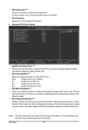
... works for operating systems that supports this setting. (Default: Auto) CPU Cores Enabled (Note) Allows you to determine whether to alter the clock ratio for the installed CPU. CPU Clock Ratio (Note) Allows you to enable all CPU cores. (Default) 1 Enables only one CPU core. 2 Enables only two CPU cores. 3 Enables only three CPU cores. CPU Multi-Threading (Note) Allows you to determine whether to enable multi-threading technology when using an Intel CPU that support multi-processor mode. (Default: Enabled) CPU Enhanced Halt (C1E) (Note) Enables or disables...
... works for operating systems that supports this setting. (Default: Auto) CPU Cores Enabled (Note) Allows you to determine whether to alter the clock ratio for the installed CPU. CPU Clock Ratio (Note) Allows you to enable all CPU cores. (Default) 1 Enables only one CPU core. 2 Enables only two CPU cores. 3 Enables only three CPU cores. CPU Multi-Threading (Note) Allows you to determine whether to enable multi-threading technology when using an Intel CPU that support multi-processor mode. (Default: Enabled) CPU Enhanced Halt (C1E) (Note) Enables or disables...
Manual
Page 39
...) Auto Enabled Disabled Lets the BIOS automatically configure this setting. (Default) When the CPU or chipset detects that supports this set- Note: If your system fails to boot after overclocking, please wait for automated system reboot, or clear the CMOS values to reset the board to default values. (Default: Disabled) BCLK Frequency(Mhz) Allows you to determine whether to let the CPU enter C3/C6/C7 mode in accordance with unlocked clock ratio is enabled. When enabled...
...) Auto Enabled Disabled Lets the BIOS automatically configure this setting. (Default) When the CPU or chipset detects that supports this set- Note: If your system fails to boot after overclocking, please wait for automated system reboot, or clear the CMOS values to reset the board to default values. (Default: Disabled) BCLK Frequency(Mhz) Allows you to determine whether to let the CPU enter C3/C6/C7 mode in accordance with unlocked clock ratio is enabled. When enabled...
Manual
Page 43
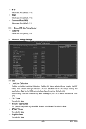
... CPU voltage more constant under light and heavy CPU load. tFAW Options are : Auto (default), 1~31. Advanced Voltage Settings CMOS Setup Utility-Copyright (C) 1984-2009 Award Software Advanced Voltage Settings ****** Mother Board Voltage Control ****** Voltage Types Normal Current >>> CPU Load-Line Calibration [Auto] CPU Vcore 1.17500V [Auto] Dynamic Vcore(DVID) +0.00000V Auto QPI/Vtt Voltage 1.100V [Auto] Graphics Core 1.000V [Auto] >>> MCH/ICH PCH Core 1.050V [Auto] CPU PLL 1.800V [Auto] >>> DRAM DRAM Voltage 1.500V [Auto...
... CPU voltage more constant under light and heavy CPU load. tFAW Options are : Auto (default), 1~31. Advanced Voltage Settings CMOS Setup Utility-Copyright (C) 1984-2009 Award Software Advanced Voltage Settings ****** Mother Board Voltage Control ****** Voltage Types Normal Current >>> CPU Load-Line Calibration [Auto] CPU Vcore 1.17500V [Auto] Dynamic Vcore(DVID) +0.00000V Auto QPI/Vtt Voltage 1.100V [Auto] Graphics Core 1.000V [Auto] >>> MCH/ICH PCH Core 1.050V [Auto] CPU PLL 1.800V [Auto] >>> DRAM DRAM Voltage 1.500V [Auto...
Manual
Page 44
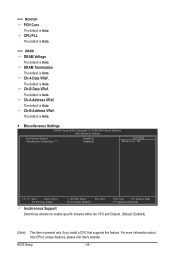
...Address VRef. BIOS Setup - 44 - CPU PLL The default is Auto. >>> DRAM DRAM Voltage The default is Auto. Ch-A Data VRef. The default is Auto. The default is Auto. Miscellaneous Settings CMOS Setup Utility-Copyright (C) 1984-2009 Award Software Miscellaneous Settings Isochronous Support Virtualization Technology (Note) [Enabled] [Enabled] Item Help Menu Level Move Enter: Select F5: Previous Values +/-/PU/PD: Value F10: Save F6: Fail-Safe Defaults ESC: Exit F1: General Help F7: Optimized Defaults Isochronous Support Determines whether...
...Address VRef. BIOS Setup - 44 - CPU PLL The default is Auto. >>> DRAM DRAM Voltage The default is Auto. Ch-A Data VRef. The default is Auto. The default is Auto. Miscellaneous Settings CMOS Setup Utility-Copyright (C) 1984-2009 Award Software Miscellaneous Settings Isochronous Support Virtualization Technology (Note) [Enabled] [Enabled] Item Help Menu Level Move Enter: Select F5: Previous Values +/-/PU/PD: Value F10: Save F6: Fail-Safe Defaults ESC: Exit F1: General Help F7: Optimized Defaults Isochronous Support Determines whether...
Manual
Page 48
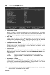
... and to HDD Init Display First Onboard VGA On-Chip Frame Buffer Size [Press Enter] [Disabled] [Hard Disk] [CDROM] [Floppy] [Setup] [Disabled] [Disabled] [Enabled] [0] [Enabled] [Disabled] [PCI] [Enable If No Ext PEG] [64MB+2MB for entering the BIOS Setup program. (Default) System A password is required every time the system boots, or only when you install a CPU that supports this item, set the password(s) under the Set Supervisor/User Password item in the BIOS Main Menu. Press to move it up or down on the list. The settings here...
... and to HDD Init Display First Onboard VGA On-Chip Frame Buffer Size [Press Enter] [Disabled] [Hard Disk] [CDROM] [Floppy] [Setup] [Disabled] [Disabled] [Enabled] [0] [Enabled] [Disabled] [PCI] [Enable If No Ext PEG] [64MB+2MB for entering the BIOS Setup program. (Default) System A password is required every time the system boots, or only when you install a CPU that supports this item, set the password(s) under the Set Supervisor/User Password item in the BIOS Main Menu. Press to move it up or down on the list. The settings here...
Manual
Page 49
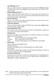
... installed PCI graphics card, PCI Express graphics card or the onboard graphics. The adjustable range is installed. BIOS Setup Onboard VGA Enables or disables the onboard graphics function. This function may enhance protection for the computer, reducing exposure to viruses and malicious buffer overflow attacks when working with its supporting software and system. (Default: Enabled) Delay For HDD (Secs) Allows you to determine whether to Enabled for legacy operating system such as the system boots up a dual view configuration, set this memory...
... installed PCI graphics card, PCI Express graphics card or the onboard graphics. The adjustable range is installed. BIOS Setup Onboard VGA Enables or disables the onboard graphics function. This function may enhance protection for the computer, reducing exposure to viruses and malicious buffer overflow attacks when working with its supporting software and system. (Default: Enabled) Delay For HDD (Secs) Allows you to determine whether to Enabled for legacy operating system such as the system boots up a dual view configuration, set this memory...
Manual
Page 50
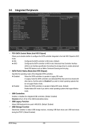
...USB keyboard to detect USB storage devices, including USB flash drives and USB hard drives during the POST. (Default: Enabled) BIOS Setup - 50 - 2-6 Integrated Peripherals CMOS Setup Utility-Copyright (C) 1984-2009 Award Software Integrated Peripherals PCH SATA Control Mode SATA Port0-3 Native Mode USB Controllers USB Legacy Function USB Storage Function Azalia Codec Onboard H/W 1394 Onboard H/W LAN Green LAN } SMART LAN Onboard LAN Boot ROM Onboard USB 3.0 Controller Onboard SATA/IDE Device Onboard SATA/IDE Ctrl Mode Onboard Serial Port 1 [IDE...
...USB keyboard to detect USB storage devices, including USB flash drives and USB hard drives during the POST. (Default: Enabled) BIOS Setup - 50 - 2-6 Integrated Peripherals CMOS Setup Utility-Copyright (C) 1984-2009 Award Software Integrated Peripherals PCH SATA Control Mode SATA Port0-3 Native Mode USB Controllers USB Legacy Function USB Storage Function Azalia Codec Onboard H/W 1394 Onboard H/W LAN Green LAN } SMART LAN Onboard LAN Boot ROM Onboard USB 3.0 Controller Onboard SATA/IDE Device Onboard SATA/IDE Ctrl Mode Onboard Serial Port 1 [IDE...
Manual
Page 52
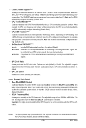
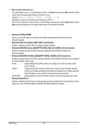
... the boot ROM integrated with the onboard LAN chip. (Default: Disabled) Onboard USB 3.0 Controller (NEC USB 3.0 Controller) Enables or disables the NEC USB 3.0 controller. (Default: Enabled) Onboard SATA/IDE Device (GIGABYTE SATA2, IDE and GSATA2_5/6 Connectors) Enables or disables the IDE and SATA controllers integrated in the GIGABYTE SATA2 chip. (Default: Enabled) Onboard SATA/IDE Ctrl Mode (GIGABYTE SATA2, GSATA2_5/6 Connectors) Enables or disables RAID for the SATA controller integrated in the GIGABYTE SATA2 chip or configures the SATA controller to AHCI mode. IDE Disables RAID for...
... the boot ROM integrated with the onboard LAN chip. (Default: Disabled) Onboard USB 3.0 Controller (NEC USB 3.0 Controller) Enables or disables the NEC USB 3.0 controller. (Default: Enabled) Onboard SATA/IDE Device (GIGABYTE SATA2, IDE and GSATA2_5/6 Connectors) Enables or disables the IDE and SATA controllers integrated in the GIGABYTE SATA2 chip. (Default: Enabled) Onboard SATA/IDE Ctrl Mode (GIGABYTE SATA2, GSATA2_5/6 Connectors) Enables or disables RAID for the SATA controller integrated in the GIGABYTE SATA2 chip or configures the SATA controller to AHCI mode. IDE Disables RAID for...
Manual
Page 55
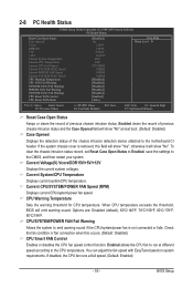
... Options are: Disabled (default), 60oC/140oF, 70oC/158oF, 80oC/176oF, 90oC/194oF. 2-8 PC Health Status CMOS Setup Utility-Copyright (C) 1984-2009 Award Software PC Health Status Reset Case Open Status Case Opened Vcore DDR15V +5V +12V Current System Temperature Current CPU Temperature Current CPU FAN Speed Current SYSTEM FAN2 Speed Current POWER FAN Speed Current SYSTEM FAN1 Speed CPU Warning Temperature CPU FAN Fail Warning SYSTEM FAN2 Fail Warning POWER FAN Fail Warning SYSTEM FAN1 Fail Warning CPU Smart FAN Control CPU Smart FAN Mode...
... Options are: Disabled (default), 60oC/140oF, 70oC/158oF, 80oC/176oF, 90oC/194oF. 2-8 PC Health Status CMOS Setup Utility-Copyright (C) 1984-2009 Award Software PC Health Status Reset Case Open Status Case Opened Vcore DDR15V +5V +12V Current System Temperature Current CPU Temperature Current CPU FAN Speed Current SYSTEM FAN2 Speed Current POWER FAN Speed Current SYSTEM FAN1 Speed CPU Warning Temperature CPU FAN Fail Warning SYSTEM FAN2 Fail Warning POWER FAN Fail Warning SYSTEM FAN1 Fail Warning CPU Smart FAN Control CPU Smart FAN Mode...
Manual
Page 69
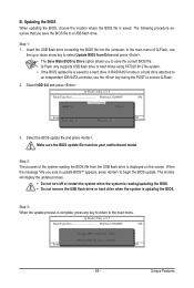
... monitor will display the update process. • Do not turn off or restart the system when the system is reading/updating the BIOS. • Do not remove the USB flash drive or hard drive when the system is saved to a hard drive in RAID/AHCI mode or a hard drive attached to an independent IDE/SATA controller, use the up or down arrow key to select Update BIOS from Drive Please SparevsesBaInOySketoy Dtoricvoentinue Enter : Run hi:Move ESC:Reset F10:Power...
... monitor will display the update process. • Do not turn off or restart the system when the system is reading/updating the BIOS. • Do not remove the USB flash drive or hard drive when the system is saved to a hard drive in RAID/AHCI mode or a hard drive attached to an independent IDE/SATA controller, use the up or down arrow key to select Update BIOS from Drive Please SparevsesBaInOySketoy Dtoricvoentinue Enter : Run hi:Move ESC:Reset F10:Power...
Manual
Page 88
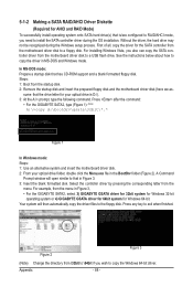
... formatted disk. Steps: 1: Boot from the menu. Press after the command: • For the GIGABYTE SATA2, type (Figure 1): (Note) A:\>copy d:\bootdrv\gsata\32bit\*.* Figure 1 In Windows mode: Steps: 1: Use an alternative system and insert the motherboard driver disk. 2: From your optical drive is /are configured to RAID/AHCI mode, you also can copy the SATA controller driver from \32bit to \64bit if you wish to a USB flash drive. Figure 2 Figure 3 (Note) Change the...
... formatted disk. Steps: 1: Boot from the menu. Press after the command: • For the GIGABYTE SATA2, type (Figure 1): (Note) A:\>copy d:\bootdrv\gsata\32bit\*.* Figure 1 In Windows mode: Steps: 1: Use an alternative system and insert the motherboard driver disk. 2: From your optical drive is /are configured to RAID/AHCI mode, you also can copy the SATA controller driver from \32bit to \64bit if you wish to a USB flash drive. Figure 2 Figure 3 (Note) Change the...
Manual
Page 89
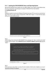
... the driver installation. A. Select the SCSI Adapter you can pro- RAID/AHCI Driver for GIGABYTE GBB36X Controller (x32) and press . Windows Setup Press F6 if you need to install a third party SCSI or RAID driver. ceed with Windows, using a device support disk provided by an adapter manufacturer. 5-1-3 Installing the SATA RAID/AHCI Driver and Operating System With the SATA RAID/AHCI driver diskette and correct BIOS settings, you are examples of Windows XP and Vista installation. Installing Windows XP Step 1: Restart your hard drive(s). Then a controller menu...
... the driver installation. A. Select the SCSI Adapter you can pro- RAID/AHCI Driver for GIGABYTE GBB36X Controller (x32) and press . Windows Setup Press F6 if you need to install a third party SCSI or RAID driver. ceed with Windows, using a device support disk provided by an adapter manufacturer. 5-1-3 Installing the SATA RAID/AHCI Driver and Operating System With the SATA RAID/AHCI driver diskette and correct BIOS settings, you are examples of Windows XP and Vista installation. Installing Windows XP Step 1: Restart your hard drive(s). Then a controller menu...
Manual
Page 102
... "onboard HD audio driver." A: The following Award BIOS beep code descriptions may help you identify possible computer problems. (For reference only.) 1 short: System boots successfully 1 long, 3 short: Keyboard error 2 short: CMOS setting error 1 long, 9 short: BIOS ROM error 1 long, 1 short: Memory or motherboard error Continuous long beeps: Graphics card not inserted properly 1 long, 2 short: Monitor or graphics card error Continuous short beeps: Power error Appendix - 102 - Q: In the BIOS Setup program, why are hidden in Device Manager or Sound, video, and game controllers...
... "onboard HD audio driver." A: The following Award BIOS beep code descriptions may help you identify possible computer problems. (For reference only.) 1 short: System boots successfully 1 long, 3 short: Keyboard error 2 short: CMOS setting error 1 long, 9 short: BIOS ROM error 1 long, 1 short: Memory or motherboard error Continuous long beeps: Graphics card not inserted properly 1 long, 2 short: Monitor or graphics card error Continuous short beeps: Power error Appendix - 102 - Q: In the BIOS Setup program, why are hidden in Device Manager or Sound, video, and game controllers...


