
Manual
Page 9
... circuit or its components. • Make sure there are connected tightly and securely. • When handling the motherboard, avoid touching any installation steps or have a problem related to the motherboard, do not remove or break motherboard S/N (Serial Number) sticker or warranty sticker provided by unplugging the power cord from the motherboard...
... circuit or its components. • Make sure there are connected tightly and securely. • When handling the motherboard, avoid touching any installation steps or have a problem related to the motherboard, do not remove or break motherboard S/N (Serial Number) sticker or warranty sticker provided by unplugging the power cord from the motherboard...
Manual
Page 27
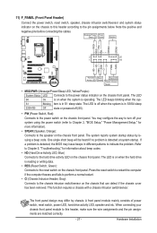
... normal restart. • CI (Chassis Intrusion Header, Gray): Connects to the chassis intrusion switch/sensor on the chassis to indicate the problem. The front panel design may issue beeps in different patterns to this header, make sure the wire assignments and the pin assignments are... removed. Note the positive and negative pins before connecting the cables. Hardware Installation One single short beep will be heard if no problem is operating. Hard Drive Activity LED Reset Switch Power LED Chassis Intrusion Header • MSG/PWR (Message/Power/Sleep LED, Yellow...
... normal restart. • CI (Chassis Intrusion Header, Gray): Connects to the chassis intrusion switch/sensor on the chassis to indicate the problem. The front panel design may issue beeps in different patterns to this header, make sure the wire assignments and the pin assignments are... removed. Note the positive and negative pins before connecting the cables. Hardware Installation One single short beep will be heard if no problem is operating. Hard Drive Activity LED Reset Switch Power LED Chassis Intrusion Header • MSG/PWR (Message/Power/Sleep LED, Yellow...
Manual
Page 33
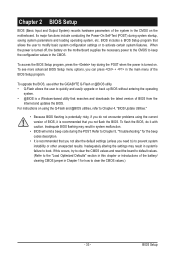
...in the CMOS. When the power is recommended that you do it is turned off, the battery on . To flash the BIOS, do not encounter problems using the current version of BIOS, it with caution. If this occurs, try to clear the CMOS values and reset the board to default values... that searches and downloads the latest version of BIOS from the Internet and updates the BIOS. BIOS Setup To upgrade the BIOS, use either the GIGABYTE Q-Flash or @BIOS utility. • Q-Flash allows the user to activate certain system features. Its major functions include conducting the Power-On Self-Test (...
...in the CMOS. When the power is recommended that you do it is turned off, the battery on . To flash the BIOS, do not encounter problems using the current version of BIOS, it with caution. If this occurs, try to clear the CMOS values and reset the board to default values... that searches and downloads the latest version of BIOS from the Internet and updates the BIOS. BIOS Setup To upgrade the BIOS, use either the GIGABYTE Q-Flash or @BIOS utility. • Q-Flash allows the user to activate certain system features. Its major functions include conducting the Power-On Self-Test (...
Manual
Page 51
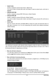
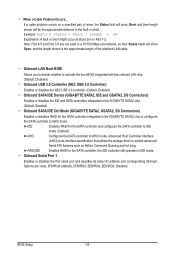
... to a Gigabit hub or a 10/100 Mbps hub, the following information for diagnosing your LAN cable: When No LAN Cable Is Attached... If no cable problem is detected on the LAN cable connected to the following message will only operate at Port..... BIOS Setup
... to a Gigabit hub or a 10/100 Mbps hub, the following information for diagnosing your LAN cable: When No LAN Cable Is Attached... If no cable problem is detected on the LAN cable connected to the following message will only operate at Port..... BIOS Setup
Manual
Page 52
... Command Queuing and hot plug. Options are not used in IDE mode. IDE Disables RAID for the SATA controller integrated in the GIGABYTE SATA2 chip or configures the SATA controller to the fault or short. Advanced Host Controller Interface (AHCI) is the approximate length of... the attached LAN cable. When a Cable Problem Occurs... Example: Part1-2 Status = Short / Length = 2m Explanation: A fault or short might occur at about 2m on a specified pair of ...
... Command Queuing and hot plug. Options are not used in IDE mode. IDE Disables RAID for the SATA controller integrated in the GIGABYTE SATA2 chip or configures the SATA controller to the fault or short. Advanced Host Controller Interface (AHCI) is the approximate length of... the attached LAN cable. When a Cable Problem Occurs... Example: Part1-2 Status = Short / Length = 2m Explanation: A fault or short might occur at about 2m on a specified pair of ...
Manual
Page 102
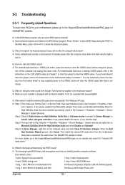
...XP only) A: Step 1: First, make sure the Microsoft UAA Bus Driver for hardware changes. You can temporarily remove the battery from GIGABYTE's website to install. eral > System). 5-3 Troubleshooting 5-3-1 Frequently Asked Questions To read more details, go back to My Computer > ...battery holder to stop supplying power to show the advanced options. A: The following Award BIOS beep code descriptions may help you identify possible computer problems. (For reference only.) 1 short: System boots successfully 1 long, 3 short: Keyboard error 2 short: CMOS setting error 1 long,...
...XP only) A: Step 1: First, make sure the Microsoft UAA Bus Driver for hardware changes. You can temporarily remove the battery from GIGABYTE's website to install. eral > System). 5-3 Troubleshooting 5-3-1 Frequently Asked Questions To read more details, go back to My Computer > ...battery holder to stop supplying power to show the advanced options. A: The following Award BIOS beep code descriptions may help you identify possible computer problems. (For reference only.) 1 short: System boots successfully 1 long, 3 short: Keyboard error 2 short: CMOS setting error 1 long,...
Manual
Page 103
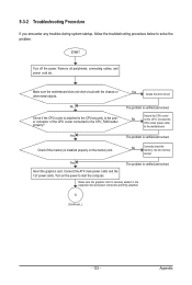
... main power cable and the 12V power cable. Turn on the power to the CPU_FAN header properly? A (Continued...) - 103 - The problem is installed properly on the CPU. Check if the memory is verified and solved. Make sure the graphics card is attached to the CPU ...securely. Is the power connector of the CPU cooler connected to start the computer. Connect the CPU cooler power cable to solve the problem. No Correctly insert the memory into the memory socket. 5-3-2 Troubleshooting Procedure If you encounter any troubles during system startup, follow the ...
... main power cable and the 12V power cable. Turn on the power to the CPU_FAN header properly? A (Continued...) - 103 - The problem is installed properly on the CPU. Check if the memory is verified and solved. Make sure the graphics card is attached to the CPU ...securely. Is the power connector of the CPU cooler connected to start the computer. Connect the CPU cooler power cable to solve the problem. No Correctly insert the memory into the memory socket. 5-3-2 Troubleshooting Procedure If you encounter any troubles during system startup, follow the ...

Manual
Page 104
... system can boot successfully. END If the procedure above is unable to solve your monitor. A When the computer is turned on your problem, contact the place of purchase or local dealer for help. Yes Turn off the computer and connect the IDE/SATA devices. The... problem is verified and solved. Yes Reinstall the operating system. The problem is verified and solved. No The IDE/SATA device, connector, or cable might fail. The problem is working properly. Appendix - 104 - Or go to the Support&...
... system can boot successfully. END If the procedure above is unable to solve your monitor. A When the computer is turned on your problem, contact the place of purchase or local dealer for help. Yes Turn off the computer and connect the IDE/SATA devices. The... problem is verified and solved. Yes Reinstall the operating system. The problem is verified and solved. No The IDE/SATA device, connector, or cable might fail. The problem is working properly. Appendix - 104 - Or go to the Support&...


