
Manual
Page 4
... Box Contents ...6 OptionalItems...6 GA-EP45-UD3LR/GA-EP45-UD3L Motherboard Layout 7 Block Diagram...8 Chapter 1 Hardware Installation 9 1-1 Installation Precautions 9 1-2 Product Specifications 10 1-3 Installing the CPU and CPU Cooler 13 1-3-1 Installing the CPU 13 1-3-2 Installing the CPU Cooler 15 1-4 Installing the Memory 16 1-4-1 Dual Channel Memory Configuration 16 1-4-2 Installing a Memory 17 1-5 Installing an Expansion Card 18 1-6 Back Panel Connectors 19 1-7 Internal Connectors 21 Chapter 2 BIOS Setup 33 2-1 Startup Screen 34 2-2 The Main Menu 35 2-3 MB Intelligent...
... Box Contents ...6 OptionalItems...6 GA-EP45-UD3LR/GA-EP45-UD3L Motherboard Layout 7 Block Diagram...8 Chapter 1 Hardware Installation 9 1-1 Installation Precautions 9 1-2 Product Specifications 10 1-3 Installing the CPU and CPU Cooler 13 1-3-1 Installing the CPU 13 1-3-2 Installing the CPU Cooler 15 1-4 Installing the Memory 16 1-4-1 Dual Channel Memory Configuration 16 1-4-2 Installing a Memory 17 1-5 Installing an Expansion Card 18 1-6 Back Panel Connectors 19 1-7 Internal Connectors 21 Chapter 2 BIOS Setup 33 2-1 Startup Screen 34 2-2 The Main Menu 35 2-3 MB Intelligent...

Manual
Page 10
...2 x PCI slots South Bridge: - 6 x SATA 3Gb/s connectors supporting up to 1 floppy disk drive Integrated in the South Bridge Up to 12 USB 2.0/1.1 ports (8 on the back panel, 4 via the USB brackets connected to 6 SATA 3Gb/s devices - Support for GA-EP45-UD3L. Only for SATA RAID 0, RAID 1, RAID 5 and RAID 10 JMicron 368 chip: - 1 x IDE connector supporting ATA-133/100/66/33 and up to 2 IDE devices iTE IT8718 chip: - 1 x floppy disk drive connector supporting up to the internal USB headers) Only for GA-EP45-UD3LR. GA-EP45-UD3LR/UD3L Motherboard...
...2 x PCI slots South Bridge: - 6 x SATA 3Gb/s connectors supporting up to 1 floppy disk drive Integrated in the South Bridge Up to 12 USB 2.0/1.1 ports (8 on the back panel, 4 via the USB brackets connected to 6 SATA 3Gb/s devices - Support for GA-EP45-UD3L. Only for SATA RAID 0, RAID 1, RAID 5 and RAID 10 JMicron 368 chip: - 1 x IDE connector supporting ATA-133/100/66/33 and up to 2 IDE devices iTE IT8718 chip: - 1 x floppy disk drive connector supporting up to the internal USB headers) Only for GA-EP45-UD3LR. GA-EP45-UD3LR/UD3L Motherboard...
Manual
Page 16
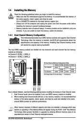
.../SS - - Intel® Flex Memory Technology offers greater flexibility to upgrade by allowing different memory sizes to be enabled if only one direction. GA-EP45-UD3LR/UD3L Motherboard - 16 - It is installed. 2. A memory module can be used and installed in Flex Memory Mode will appear during the POST. 1-4 Installing the Memory Read the following guidelines before you are unable to insert the memory, switch the direction. 1-4-1 Dual Channel Memory Configuration This motherboard provides four DDR2 memory sockets and supports Dual Channel Technology.
.../SS - - Intel® Flex Memory Technology offers greater flexibility to upgrade by allowing different memory sizes to be enabled if only one direction. GA-EP45-UD3LR/UD3L Motherboard - 16 - It is installed. 2. A memory module can be used and installed in Flex Memory Mode will appear during the POST. 1-4 Installing the Memory Read the following guidelines before you are unable to insert the memory, switch the direction. 1-4-1 Dual Channel Memory Configuration This motherboard provides four DDR2 memory sockets and supports Dual Channel Technology.

Manual
Page 18
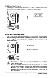
... the power outlet before you begin to the chassis back panel with a screw. 5. Locate an expansion slot that came with your card. Secure the card's metal bracket to install an expansion card: • Make sure the motherboard supports the expansion card. Make sure the card is fully inserted into the slot. 4. If necessary, go to BIOS Setup to prevent hardware damage. GA-EP45-UD3LR/UD3L Motherboard - 18 - PCI Express x1 Slot PCI Express x16 Slot PCI Slot Follow...
... the power outlet before you begin to the chassis back panel with a screw. 5. Locate an expansion slot that came with your card. Secure the card's metal bracket to install an expansion card: • Make sure the motherboard supports the expansion card. Make sure the card is fully inserted into the slot. 4. If necessary, go to BIOS Setup to prevent hardware damage. GA-EP45-UD3LR/UD3L Motherboard - 18 - PCI Express x1 Slot PCI Express x16 Slot PCI Slot Follow...
Manual
Page 31
... sure to remove the jumper cap from the power outlet before clearing the CMOS values. • After clearing the CMOS values and before turning on the two pins to temporarily short the two pins or use a metal object like a screwdriver to Chapter 2, "BIOS Setup," for a few seconds. 18) CI (Chassis Intrusion Header) This motherboard provides a chassis detection feature that detects if the chassis cover has been removed. Failure to do so...
... sure to remove the jumper cap from the power outlet before clearing the CMOS values. • After clearing the CMOS values and before turning on the two pins to temporarily short the two pins or use a metal object like a screwdriver to Chapter 2, "BIOS Setup," for a few seconds. 18) CI (Chassis Intrusion Header) This motherboard provides a chassis detection feature that detects if the chassis cover has been removed. Failure to do so...

Manual
Page 34
...enter BIOS Setup first. To exit Boot Menu, press . A. You can be based on page 49. : BIOS SETUP\Q-FLASH Press the key to enter BIOS Setup or to access the Q-Flash utility in Boot Menu is effective for subsequent access to access the Q-Flash utility directly without entering BIOS Setup. To show the BIOS POST screen. GA-EP45-UD3LR/UD3L Motherboard - 34 - 2-1 Startup Screen The following screens may appear when the computer boots. In Boot Menu, use the up hard drive data using the driver disk, the key can access Boot Menu again to change the first boot device...
...enter BIOS Setup first. To exit Boot Menu, press . A. You can be based on page 49. : BIOS SETUP\Q-FLASH Press the key to enter BIOS Setup or to access the Q-Flash utility in Boot Menu is effective for subsequent access to access the Q-Flash utility directly without entering BIOS Setup. To show the BIOS POST screen. GA-EP45-UD3LR/UD3L Motherboard - 34 - 2-1 Startup Screen The following screens may appear when the computer boots. In Boot Menu, use the up hard drive data using the driver disk, the key can access Boot Menu again to change the first boot device...
Manual
Page 35
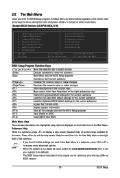
... of the Main Menu. BIOS Setup Press to display a help screen. Use arrow keys to move among the items and press to accept or enter a sub-menu. (Sample BIOS Version: GA-EP45-UD3L E19) CMOS Setup Utility-Copyright (C) 1984-2008 Award Software MB Intelligent Tweaker(M.I.T.) Standard CMOS Features Advanced BIOS Features Integrated Peripherals Power Management Setup PnP/PCI Configurations PC Health Status Load Fail-Safe Defaults Load Optimized Defaults Set Supervisor Password Set User Password Save & Exit Setup Exit Without...
... of the Main Menu. BIOS Setup Press to display a help screen. Use arrow keys to move among the items and press to accept or enter a sub-menu. (Sample BIOS Version: GA-EP45-UD3L E19) CMOS Setup Utility-Copyright (C) 1984-2008 Award Software MB Intelligent Tweaker(M.I.T.) Standard CMOS Features Advanced BIOS Features Integrated Peripherals Power Management Setup PnP/PCI Configurations PC Health Status Load Fail-Safe Defaults Load Optimized Defaults Set Supervisor Password Set User Password Save & Exit Setup Exit Without...

Manual
Page 36
... system/CPU temperature, system voltage and fan speed, etc. Load Fail-Safe Defaults Fail-Safe defaults are factory settings for the most stable, minimal-performance system operations. Load Optimized Defaults Optimized defaults are factory settings for optimal-performance system operations. Set Supervisor Password Change, set , or disable password. You can also carry out this menu to configure the system time and date, hard drive types, floppy disk drive types, and the type of the and keys (For the Main Menu Only...
... system/CPU temperature, system voltage and fan speed, etc. Load Fail-Safe Defaults Fail-Safe defaults are factory settings for the most stable, minimal-performance system operations. Load Optimized Defaults Optimized defaults are factory settings for optimal-performance system operations. Set Supervisor Password Change, set , or disable password. You can also carry out this menu to configure the system time and date, hard drive types, floppy disk drive types, and the type of the and keys (For the Main Menu Only...
Manual
Page 38
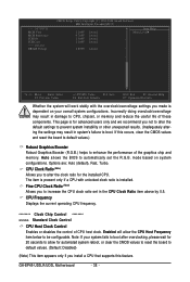
... Displays the current operating CPU frequency. ******** Clock Chip Control Standard Clock Control CPU Host Clock Control Enables or disables the control of the graphics chip and memory. Note: If your overall system configurations. >>> MCH/ICH MCH Core MCH Reference ICH I/O ICH Core >>> DRAM DRAM Voltage CMOS Setup Utility-Copyright (C) 1984-2008 Award Software MB Intelligent Tweaker(M.I.T.) 1.100V 0.760V 1.500V 1.100V [Auto] [Auto] [Auto] [Auto] Item Help Menu Level 1.800V [Auto] Move Enter: Select F5: Previous Values +/-/PU/PD: Value F10: Save F6: Fail-Safe Defaults...
... Displays the current operating CPU frequency. ******** Clock Chip Control Standard Clock Control CPU Host Clock Control Enables or disables the control of the graphics chip and memory. Note: If your overall system configurations. >>> MCH/ICH MCH Core MCH Reference ICH I/O ICH Core >>> DRAM DRAM Voltage CMOS Setup Utility-Copyright (C) 1984-2008 Award Software MB Intelligent Tweaker(M.I.T.) 1.100V 0.760V 1.500V 1.100V [Auto] [Auto] [Auto] [Auto] Item Help Menu Level 1.800V [Auto] Move Enter: Select F5: Previous Values +/-/PU/PD: Value F10: Save F6: Fail-Safe Defaults...
Manual
Page 46
... parameters of floppy disk drive installed in your hard drive specifications. Landing Zone Sector Landing zone. Floppy 3 Mode Support Allows you to manually enter the specifications of the two methods below: • Auto • None Access Mode Lets BIOS automatically detect IDE/SATA devices during the POST. (Default) If no IDE/SATA devices are used , set this item to None so the system will stop for an error during the POST. Extended Memory The amount of memory installed on this channel. Memory These fields...
... parameters of floppy disk drive installed in your hard drive specifications. Landing Zone Sector Landing zone. Floppy 3 Mode Support Allows you to manually enter the specifications of the two methods below: • Auto • None Access Mode Lets BIOS automatically detect IDE/SATA devices during the POST. (Default) If no IDE/SATA devices are used , set this item to None so the system will stop for an error during the POST. Extended Memory The amount of memory installed on this channel. Memory These fields...

Manual
Page 47
... available devices. BIOS Setup Press to accept. HDD S.M.A.R.T. First/Second/Third Boot Device Specifies the boot order from the installed hard drives. Options are: Floppy, LS120, Hard Disk, CDROM, ZIP, USB-FDD, USB-ZIP, USB-CDROM, USB-HDD, Legacy LAN, Disabled. Setup System A password is only required for entering the BIOS Setup program. After configuring this menu when finished. Use the up or down arrow key to select a device and press to exit this item, set the password(s) under the Set Supervisor/User Password item in the BIOS Main Menu...
... available devices. BIOS Setup Press to accept. HDD S.M.A.R.T. First/Second/Third Boot Device Specifies the boot order from the installed hard drives. Options are: Floppy, LS120, Hard Disk, CDROM, ZIP, USB-FDD, USB-ZIP, USB-CDROM, USB-HDD, Legacy LAN, Disabled. Setup System A password is only required for entering the BIOS Setup program. After configuring this menu when finished. Use the up or down arrow key to select a device and press to exit this item, set the password(s) under the Set Supervisor/User Password item in the BIOS Main Menu...
Manual
Page 50
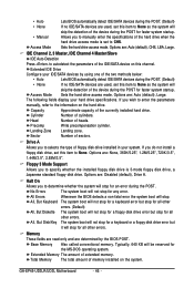
... Peripherals CMOS Setup Utility-Copyright (C) 1984-2008 Award Software Integrated Peripherals SATA RAID/AHCI Mode SATA AHCI Mode SATA Port0-3 Native Mode USB Controller USB 2.0 Controller USB Keyboard Support USB Mouse Support Legacy USB storage detect Azalia Codec Onboard H/W LAN Green LAN SMART LAN Onboard LAN Boot ROM Onboard IDE Controller Onboard Serial Port 1 Onboard Parallel Port Parallel Port Mode [Disabled] [Disabled] [Disabled] [Enabled] [Enabled] [Enabled] [Disabled] [Enabled] [Auto] [Enabled] [Disbabled] [Press Enter] [Disabled] [Enabled] [3F8...
... Peripherals CMOS Setup Utility-Copyright (C) 1984-2008 Award Software Integrated Peripherals SATA RAID/AHCI Mode SATA AHCI Mode SATA Port0-3 Native Mode USB Controller USB 2.0 Controller USB Keyboard Support USB Mouse Support Legacy USB storage detect Azalia Codec Onboard H/W LAN Green LAN SMART LAN Onboard LAN Boot ROM Onboard IDE Controller Onboard Serial Port 1 Onboard Parallel Port Parallel Port Mode [Disabled] [Disabled] [Disabled] [Enabled] [Enabled] [Enabled] [Disabled] [Enabled] [Auto] [Enabled] [Disbabled] [Press Enter] [Disabled] [Enabled] [3F8...
Manual
Page 51
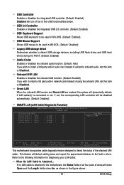
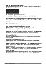
... to install a 3rd party add-in audio card instead of using the onboard LAN, set this item to detect the status of the USB functionalities below. BIOS Setup USB 2.0 Controller Enables or disables the integrated USB 2.0 controller. (Default: Enabled) USB Keyboard Support Allows USB keyboard to be used in MS-DOS. (Default: Enabled) USB Mouse Support Allows USB mouse to be used in network card instead of wires will be disabled automatically. (Default: Disabled) SMART LAN (LAN Cable Diagnostic Function) CMOS Setup Utility-Copyright (C) 1984-2008 Award Software SMART LAN Start...
... to install a 3rd party add-in audio card instead of using the onboard LAN, set this item to detect the status of the USB functionalities below. BIOS Setup USB 2.0 Controller Enables or disables the integrated USB 2.0 controller. (Default: Enabled) USB Keyboard Support Allows USB keyboard to be used in MS-DOS. (Default: Enabled) USB Mouse Support Allows USB mouse to be used in network card instead of wires will be disabled automatically. (Default: Disabled) SMART LAN (LAN Cable Diagnostic Function) CMOS Setup Utility-Copyright (C) 1984-2008 Award Software SMART LAN Start...
Manual
Page 52
... to activate the boot ROM integrated with the onboard LAN chip. (Default: Disabled) Onboard IDE Controller (JMicron 368 Chip) Enables or disables the IDE controller integrated in Windows mode or when the LAN Boot ROM is the approximate length of the attached LAN cable. Example: Part1-2 Status = Short / Length = 2m Explanation: A fault or short might occur at Port..... Options are : SPP (Standard Parallel Port)(default), EPP (Enhanced Parallel Port), ECP (Extended Capabilities Port), ECP+EPP. GA-EP45-UD3LR/UD3L Motherboard - 52 - When LAN Cable Is Functioning...
... to activate the boot ROM integrated with the onboard LAN chip. (Default: Disabled) Onboard IDE Controller (JMicron 368 Chip) Enables or disables the IDE controller integrated in Windows mode or when the LAN Boot ROM is the approximate length of the attached LAN cable. Example: Part1-2 Status = Short / Length = 2m Explanation: A fault or short might occur at Port..... Options are : SPP (Standard Parallel Port)(default), EPP (Enhanced Parallel Port), ECP (Extended Capabilities Port), ECP+EPP. GA-EP45-UD3LR/UD3L Motherboard - 52 - When LAN Cable Is Functioning...
Manual
Page 71
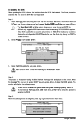
... a floppy disk. The monitor will display the update process. • Do not turn off or restart the system when the system is reading/updating the BIOS. • Do not remove the floppy disk, USB flash drive, or hard drive when the system is saved to a hard drive in RAID/AHCI mode or a hard drive attached to an independent IDE/SATA controller, use the up or down arrow key to select Update BIOS from Drive and press . • The Save Main BIOS to Drive option allows...
... a floppy disk. The monitor will display the update process. • Do not turn off or restart the system when the system is reading/updating the BIOS. • Do not remove the floppy disk, USB flash drive, or hard drive when the system is saved to a hard drive in RAID/AHCI mode or a hard drive attached to an independent IDE/SATA controller, use the up or down arrow key to select Update BIOS from Drive and press . • The Save Main BIOS to Drive option allows...
Manual
Page 74
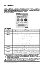
... restore to specify a C.I.A.2 level and a Smart Fan mode. The Smart tab allows you to default values. You can select memory module on the CPU temperature thresholds you to monitor hardware temperature, voltage and fan speed and set . GA-EP45-UD3LR/UD3L Motherboard - 74 - You can choose the alert sound from a profile. The Graphics tab allows you set temperature/fan speed alarm. The HW Monitor tab allows you to change system clock settings and voltages settings using the sliders. • Save allows...
... restore to specify a C.I.A.2 level and a Smart Fan mode. The Smart tab allows you to default values. You can select memory module on the CPU temperature thresholds you to monitor hardware temperature, voltage and fan speed and set . GA-EP45-UD3LR/UD3L Motherboard - 74 - You can choose the alert sound from a profile. The Graphics tab allows you set temperature/fan speed alarm. The HW Monitor tab allows you to change system clock settings and voltages settings using the sliders. • Save allows...
Manual
Page 79
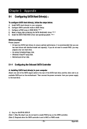
...performance, it is set to the hard drive. Installing SATA hard drive(s) in your power supply to AHCI or RAID mode. - 79 - Chapter 5 Appendix 5-1 Configuring SATA Hard Drive(s) To configure SATA hard drive(s), follow the steps below: A. B. Install SATA hard drive(s) in your computer Attach one hard drive. • An empty formatted floppy disk. • Windows Vista/XP setup disk. • Motherboard driver disk. 5-1-1 Configuring the Onboard SATA Controller A. Only for GA-EP45-UD3LR. (Note 1) Skip this step if you use two hard drives with identical model and capacity). Appendix...
...performance, it is set to the hard drive. Installing SATA hard drive(s) in your power supply to AHCI or RAID mode. - 79 - Chapter 5 Appendix 5-1 Configuring SATA Hard Drive(s) To configure SATA hard drive(s), follow the steps below: A. B. Install SATA hard drive(s) in your computer Attach one hard drive. • An empty formatted floppy disk. • Windows Vista/XP setup disk. • Motherboard driver disk. 5-1-1 Configuring the Onboard SATA Controller A. Only for GA-EP45-UD3LR. (Note 1) Skip this step if you use two hard drives with identical model and capacity). Appendix...
Manual
Page 80
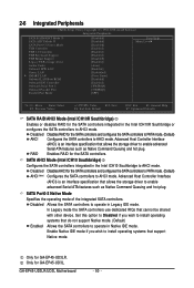
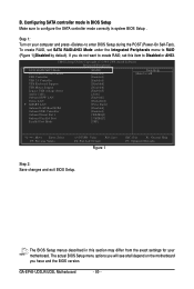
... create RAID, set SATA RAID/AHCI Mode under the Integrated Peripherals menu to configure the SATA controller mode correctly in system BIOS Setup . CMOS Setup Utility-Copyright (C) 1984-2008 Award Software Integrated Peripherals SATA RAID/AHCI Mode SATA Port0-3 Native Mode USB Controller USB 2.0 Controller USB Keyboard Support USB Mouse Support Legacy USB storage detect Azalia Codec Onboard H/W LAN Green LAN SMART LAN Onboard LAN Boot ROM Onboard IDE Controller Onboard Serial Port 1 Onboard Parallel Port Parallel Port Mode [RAID] [Disabled] [Enabled] [Enabled] [Disabled] [Disabled...
... create RAID, set SATA RAID/AHCI Mode under the Integrated Peripherals menu to configure the SATA controller mode correctly in system BIOS Setup . CMOS Setup Utility-Copyright (C) 1984-2008 Award Software Integrated Peripherals SATA RAID/AHCI Mode SATA Port0-3 Native Mode USB Controller USB 2.0 Controller USB Keyboard Support USB Mouse Support Legacy USB storage detect Azalia Codec Onboard H/W LAN Green LAN SMART LAN Onboard LAN Boot ROM Onboard IDE Controller Onboard Serial Port 1 Onboard Parallel Port Parallel Port Mode [RAID] [Disabled] [Enabled] [Enabled] [Disabled] [Disabled...
Manual
Page 87
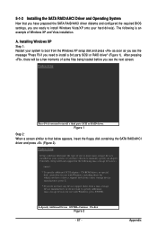
... screen. Figure 1 Step 2: When a screen similar to install Windows Vista/XP onto your system, or you have chosen to specify additional mass storage devices for use with Windows, including those for use with Windows, press ENTER. 5-1-3 Installing the SATA RAID/AHCI Driver and Operating System Now that you have prepared the SATA RAID/AHCI driver diskette and configured the required BIOS settings, you are ready to that below appears, insert the floppy disk containing the SATA RAID/AHCI driver...
... screen. Figure 1 Step 2: When a screen similar to install Windows Vista/XP onto your system, or you have chosen to specify additional mass storage devices for use with Windows, including those for use with Windows, press ENTER. 5-1-3 Installing the SATA RAID/AHCI Driver and Operating System Now that you have prepared the SATA RAID/AHCI driver diskette and configured the required BIOS settings, you are ready to that below appears, insert the floppy disk containing the SATA RAID/AHCI driver...
Manual
Page 99
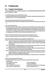
...HD audio driver." Then install the onboard HD audio driver from the motherboard driver disk or download the audio driver from GIGABYTE's website to enter BIOS Setup during the POST mean? A: The following Award BIOS beep code descriptions may help you identify possible computer problems. (For reference only.) 1 short: System boots successfully 1 long, 3 short: Keyboard error 2 short: CMOS setting error 1 long, 9 short: BIOS ROM error 1 long, 1 short: Memory or motherboard error Continuous long beeps: Graphics card not inserted properly 1 long, 2 short: Monitor or graphics card error...
...HD audio driver." Then install the onboard HD audio driver from the motherboard driver disk or download the audio driver from GIGABYTE's website to enter BIOS Setup during the POST mean? A: The following Award BIOS beep code descriptions may help you identify possible computer problems. (For reference only.) 1 short: System boots successfully 1 long, 3 short: Keyboard error 2 short: CMOS setting error 1 long, 9 short: BIOS ROM error 1 long, 1 short: Memory or motherboard error Continuous long beeps: Graphics card not inserted properly 1 long, 2 short: Monitor or graphics card error...


