Manual
Page 1
GA-EP45-UD3LR/ GA-EP45-UD3L LGA775 socket motherboard for Intel® CoreTM processor family/ Intel® Pentium® processor family/Intel® Celeron® processor family User's Manual Rev. 1101 12ME-EP45UD3L-1101R
GA-EP45-UD3LR/ GA-EP45-UD3L LGA775 socket motherboard for Intel® CoreTM processor family/ Intel® Pentium® processor family/Intel® Celeron® processor family User's Manual Rev. 1101 12ME-EP45UD3L-1101R
Manual
Page 2
Motherboard GA-EP45-UD3LR/GA-EP45-UD3L Oct. 8, 2008 Motherboard GA-EP45-UD3LR/ GA-EP45-UD3L Oct. 8, 2008
Motherboard GA-EP45-UD3LR/GA-EP45-UD3L Oct. 8, 2008 Motherboard GA-EP45-UD3LR/ GA-EP45-UD3L Oct. 8, 2008
Manual
Page 3
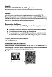
... order to their respective owners. The trademarks mentioned in the use GIGABYTE's unique features, read or download the information on/from the Support\Motherboard\Technology Guide page on your motherboard revision before updating motherboard BIOS, drivers, or when looking for technical information. For product-related...BYTE TECHNOLOGY CO., LTD. For example, "REV: 1.0" means the revision of the motherboard is the property of this manual are legally registered to assist in this product, GIGABYTE provides the following types of documentations: For quick set-up of the ...
... order to their respective owners. The trademarks mentioned in the use GIGABYTE's unique features, read or download the information on/from the Support\Motherboard\Technology Guide page on your motherboard revision before updating motherboard BIOS, drivers, or when looking for technical information. For product-related...BYTE TECHNOLOGY CO., LTD. For example, "REV: 1.0" means the revision of the motherboard is the property of this manual are legally registered to assist in this product, GIGABYTE provides the following types of documentations: For quick set-up of the ...

Manual
Page 4
Table of Contents Box Contents ...6 OptionalItems...6 GA-EP45-UD3LR/GA-EP45-UD3L Motherboard Layout 7 Block Diagram...8 Chapter 1 Hardware Installation 9 1-1 Installation Precautions 9 1-2 Product Specifications 10 1-3 Installing the CPU and CPU Cooler 13 1-3-1 Installing the CPU 13 1-3-2 Installing the CPU ...
Table of Contents Box Contents ...6 OptionalItems...6 GA-EP45-UD3LR/GA-EP45-UD3L Motherboard Layout 7 Block Diagram...8 Chapter 1 Hardware Installation 9 1-1 Installation Precautions 9 1-2 Product Specifications 10 1-3 Installing the CPU and CPU Cooler 13 1-3-1 Installing the CPU 13 1-3-2 Installing the CPU ...
Manual
Page 6
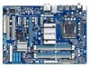
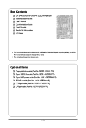
The box contents are for reference only. Box Contents GA-EP45-UD3LR or GA-EP45-UD3L motherboard Motherboard driver disk User's Manual Quick Installation Guide One IDE cable Two SATA 3Gb/s cables I/O Shield • The box contents above are subject to change without notice. • The motherboard image is for reference only and the actual items shall depend on...
The box contents are for reference only. Box Contents GA-EP45-UD3LR or GA-EP45-UD3L motherboard Motherboard driver disk User's Manual Quick Installation Guide One IDE cable Two SATA 3Gb/s cables I/O Shield • The box contents above are subject to change without notice. • The motherboard image is for reference only and the actual items shall depend on...
Manual
Page 7
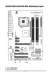
Only for GA-EP45-UD3LR. GA-EP45-UD3LR/GA-EP45-UD3L Motherboard Layout KB_MS R_SPDIF R_USB_1 R_USB_2 R_USB_3 ATX_12V LGA775 CPU_FAN PWR_FAN PHASE LED ATX DDR2_1 GA-EP45-UD3LR/GA-EP45-UD3L DDR2_2 DDR2_3 DDR2_4 FDD SYS_FAN2 USB_LAN F_AUDIO SYS_FAN1 AUDIO Intel® P45 RTL8111C PCIEX1_1 PCIEX1_2 PCIEX16 CODEC SPDIF_O SPDIF_I PCIEX1_3 PCIEX1_4 B_BIOS M_BIOS BAT PCI1 ... CD_IN CI Intel® ICH10R Intel® ICH10 SATA2_3 SATA2_0 SATA2_4 SATA2_ 1 JMicron 368 IDE SATA2_5 SATA2_2 F_USB1 F_PANEL PWR_LED COMA LPT F_USB2 Only for GA-EP45-UD3L. - 7 -
Only for GA-EP45-UD3LR. GA-EP45-UD3LR/GA-EP45-UD3L Motherboard Layout KB_MS R_SPDIF R_USB_1 R_USB_2 R_USB_3 ATX_12V LGA775 CPU_FAN PWR_FAN PHASE LED ATX DDR2_1 GA-EP45-UD3LR/GA-EP45-UD3L DDR2_2 DDR2_3 DDR2_4 FDD SYS_FAN2 USB_LAN F_AUDIO SYS_FAN1 AUDIO Intel® P45 RTL8111C PCIEX1_1 PCIEX1_2 PCIEX16 CODEC SPDIF_O SPDIF_I PCIEX1_3 PCIEX1_4 B_BIOS M_BIOS BAT PCI1 ... CD_IN CI Intel® ICH10R Intel® ICH10 SATA2_3 SATA2_0 SATA2_4 SATA2_ 1 JMicron 368 IDE SATA2_5 SATA2_2 F_USB1 F_PANEL PWR_LED COMA LPT F_USB2 Only for GA-EP45-UD3L. - 7 -
Manual
Page 9
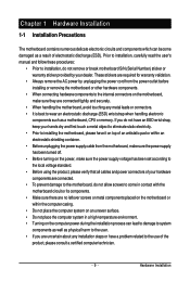
...system on an uneven surface. • Do not place the computer system in a high-temperature environment. • Turning on the motherboard, make sure the power supply voltage has been set according to the local voltage standard. • Before using the product, please... such as a result of the product, please consult a certified computer technician. - 9 - Chapter 1 Hardware Installation 1-1 Installation Precautions The motherboard contains numerous delicate electronic circuits and components which can lead to damage to system components as well as physical harm to the user. •...
...system on an uneven surface. • Do not place the computer system in a high-temperature environment. • Turning on the motherboard, make sure the power supply voltage has been set according to the local voltage standard. • Before using the product, please... such as a result of the product, please consult a certified computer technician. - 9 - Chapter 1 Hardware Installation 1-1 Installation Precautions The motherboard contains numerous delicate electronic circuits and components which can lead to damage to system components as well as physical harm to the user. •...

Manual
Page 10
...GA-EP45-UD3L. Support for SATA RAID 0, RAID 1, RAID 5 and RAID 10 JMicron 368 chip: - 1 x IDE connector supporting ATA-133/100/66/33 and up to 2 IDE devices iTE IT8718 chip: - 1 x floppy disk drive connector supporting up to the internal USB headers) Only for GA-EP45-UD3LR. GA-EP45-UD3LR/UD3L Motherboard...(Note 1) Dual channel memory architecture Support for DDR2 1366/1066/800/667 MHz memory modules (Go to GIGABYTE's website for the latest memory support list.) Realtek ALC888 codec High Definition Audio 2/4/5.1/7.1-channel ...
...GA-EP45-UD3L. Support for SATA RAID 0, RAID 1, RAID 5 and RAID 10 JMicron 368 chip: - 1 x IDE connector supporting ATA-133/100/66/33 and up to 2 IDE devices iTE IT8718 chip: - 1 x floppy disk drive connector supporting up to the internal USB headers) Only for GA-EP45-UD3LR. GA-EP45-UD3LR/UD3L Motherboard...(Note 1) Dual channel memory architecture Support for DDR2 1366/1066/800/667 MHz memory modules (Go to GIGABYTE's website for the latest memory support list.) Realtek ALC888 codec High Definition Audio 2/4/5.1/7.1-channel ...
Manual
Page 12
... CPU/System fan speed control function is supported will depend on the CPU/ System cooler you install. (Note 3) Available functions in EasyTune may differ by motherboard model. GA-EP45-UD3LR/UD3L Motherboard - 12 -
... CPU/System fan speed control function is supported will depend on the CPU/ System cooler you install. (Note 3) Available functions in EasyTune may differ by motherboard model. GA-EP45-UD3LR/UD3L Motherboard - 12 -
Manual
Page 13
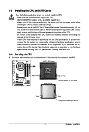
...; Apply an even and thin layer of thermal grease on the computer if the CPU cooler is not recom- Locate the alignment keys on the motherboard CPU socket and the notches on the CPU - 13 - The CPU cannot be set the frequency beyond hardware specifications since it does not meet...the computer and unplug the power cord from the power outlet before you begin to install the CPU: • Make sure that the motherboard supports the CPU. (Go to GIGABYTE's website for the peripherals. If you may occur. • Set the CPU host frequency in accordance with the CPU specifications. LGA775 ...
...; Apply an even and thin layer of thermal grease on the computer if the CPU cooler is not recom- Locate the alignment keys on the motherboard CPU socket and the notches on the CPU - 13 - The CPU cannot be set the frequency beyond hardware specifications since it does not meet...the computer and unplug the power cord from the power outlet before you begin to install the CPU: • Make sure that the motherboard supports the CPU. (Go to GIGABYTE's website for the peripherals. If you may occur. • Set the CPU host frequency in accordance with the CPU specifications. LGA775 ...

Manual
Page 14
... socket lever. Step 5: Once the CPU is not installed.) Step 4: Hold the CPU with the socket alignment keys) and gently insert the CPU into the motherboard CPU socket. GA-EP45-UD3LR/UD3L Motherboard - 14 - B.
... socket lever. Step 5: Once the CPU is not installed.) Step 4: Hold the CPU with the socket alignment keys) and gently insert the CPU into the motherboard CPU socket. GA-EP45-UD3LR/UD3L Motherboard - 14 - B.
Manual
Page 15
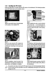
... After the installation, check the back of the CPU cooler to the CPU fan header (CPU_FAN) on the motherboard. Step 6: Finally, attach the power connector of the motherboard. Inadequately removing the CPU cooler may adhere to the CPU. Direction of the Arrow Sign on the Male Push... damage the CPU. - 15 - Hardware Installation 1-3-2 Installing the CPU Cooler Follow the steps below to correctly install the CPU cooler on the motherboard. (The following procedure uses Intel® boxed cooler as the picture above, the installation is to install.) Step 3: Place the cooler atop ...
... After the installation, check the back of the CPU cooler to the CPU fan header (CPU_FAN) on the motherboard. Step 6: Finally, attach the power connector of the motherboard. Inadequately removing the CPU cooler may adhere to the CPU. Direction of the Arrow Sign on the Male Push... damage the CPU. - 15 - Hardware Installation 1-3-2 Installing the CPU Cooler Follow the steps below to correctly install the CPU cooler on the motherboard. (The following procedure uses Intel® boxed cooler as the picture above, the installation is to install.) Step 3: Place the cooler atop ...
Manual
Page 16
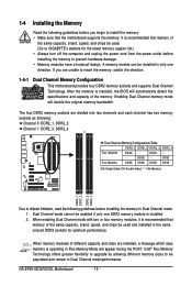
...memory mode will automatically detect the specifications and capacity of the same capacity, brand, speed, and chips be used . (Go to GIGABYTE's website for optimum performance. When enabling Dual Channel mode with two or four memory modules, it is installed, the BIOS will double ...the power cord from the power outlet before installing the memory to prevent hardware damage. • Memory modules have a foolproof design. GA-EP45-UD3LR/UD3L Motherboard - 16 - 1-4 Installing the Memory Read the following guidelines before you are divided into two channels and each channel has two memory...
...memory mode will automatically detect the specifications and capacity of the same capacity, brand, speed, and chips be used . (Go to GIGABYTE's website for optimum performance. When enabling Dual Channel mode with two or four memory modules, it is installed, the BIOS will double ...the power cord from the power outlet before installing the memory to prevent hardware damage. • Memory modules have a foolproof design. GA-EP45-UD3LR/UD3L Motherboard - 16 - 1-4 Installing the Memory Read the following guidelines before you are divided into two channels and each channel has two memory...
Manual
Page 17
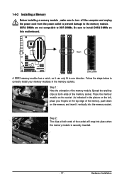
... the socket will snap into the memory socket. Spread the retaining clips at both ends of the memory module. Place the memory module on this motherboard. Hardware Installation Step 2: The clips at both ends of the memory, push down on the left, place your memory modules in one direction. Step 1: Note...
... the socket will snap into the memory socket. Spread the retaining clips at both ends of the memory module. Place the memory module on this motherboard. Hardware Installation Step 2: The clips at both ends of the memory, push down on the left, place your memory modules in one direction. Step 1: Note...

Manual
Page 18
...computer. Install the driver provided with the expansion card in the slot. 3. Carefully read the manual that supports your operating system. GA-EP45-UD3LR/UD3L Motherboard - 18 - Turn on the card until it is fully inserted into the slot. 4. Secure the card's metal bracket to ...install an expansion card: • Make sure the motherboard supports the expansion card. 1-5 Installing an Expansion Card Read the following guidelines ...
...computer. Install the driver provided with the expansion card in the slot. 3. Carefully read the manual that supports your operating system. GA-EP45-UD3LR/UD3L Motherboard - 18 - Turn on the card until it is fully inserted into the slot. 4. Secure the card's metal bracket to ...install an expansion card: • Make sure the motherboard supports the expansion card. 1-5 Installing an Expansion Card Read the following guidelines ...
Manual
Page 19
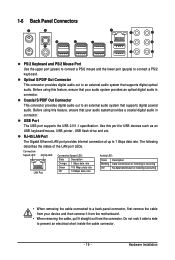
... that your audio system provides an optical digital audio in connector. Before using this feature, ensure that your device and then remove it from the motherboard. • When removing the cable, pull it straight out from the connector. Use this port for USB devices such as an USB keyboard/mouse, USB...
... that your audio system provides an optical digital audio in connector. Before using this feature, ensure that your device and then remove it from the motherboard. • When removing the cable, pull it straight out from the connector. Use this port for USB devices such as an USB keyboard/mouse, USB...
Manual
Page 20
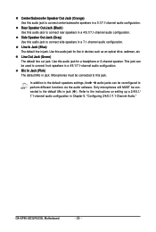
... the instructions on setting up a 2/4/5.1/ 7.1-channel audio configuration in jack. Use this audio jack for line in devices such as an optical drive, walkman, etc. GA-EP45-UD3LR/UD3L Motherboard - 20 - Line Out Jack (Green) The default line out jack. Use this audio jack for a headphone or 2-channel speaker. Center/Subwoofer Speaker Out Jack...
... the instructions on setting up a 2/4/5.1/ 7.1-channel audio configuration in jack. Use this audio jack for line in devices such as an optical drive, walkman, etc. GA-EP45-UD3LR/UD3L Motherboard - 20 - Line Out Jack (Green) The default line out jack. Use this audio jack for a headphone or 2-channel speaker. Center/Subwoofer Speaker Out Jack...

Manual
Page 21
... devices and your devices are compliant with the connectors you wish to connect. • Before installing the devices, be sure to the connector on the motherboard. - 21 -
... devices and your devices are compliant with the connectors you wish to connect. • Before installing the devices, be sure to the connector on the motherboard. - 21 -
Manual
Page 22
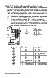
...12V GND PS_ON(soft On/Off) GND GND GND -5V +5V +5V +5V (Only for 2x12-pinATX) GND (Only for 2x12-pin ATX) GA-EP45-UD3LR/UD3L Motherboard - 22 - Before connecting the power connector, first make sure the power supply is recommended that a power supply that can withstand high power consumption ... is not connected, the computer will not start. • To meet expansion requirements, it is turned off and all the components on the motherboard. Connect the power supply cable to the CPU. The power connector possesses a foolproof design. Do not insert the power supply cable into pins...
...12V GND PS_ON(soft On/Off) GND GND GND -5V +5V +5V +5V (Only for 2x12-pinATX) GND (Only for 2x12-pin ATX) GA-EP45-UD3LR/UD3L Motherboard - 22 - Before connecting the power connector, first make sure the power supply is recommended that a power supply that can withstand high power consumption ... is not connected, the computer will not start. • To meet expansion requirements, it is turned off and all the components on the motherboard. Connect the power supply cable to the CPU. The power connector possesses a foolproof design. Do not insert the power supply cable into pins...

Manual
Page 23
... a 4-pin CPU fan header (CPU_FAN), a 3-pin (SYS_FAN1) and a 4-pin (SYS_FAN2) system fan headers, and a 3-pin power fan header (PWR_FAN). Hardware Installation The motherboard supports CPU fan speed control, which requires the use of different color. 34 33 2 1 - 23 - Overheating may hang. • These fan headers are : 360 KB, ...
... a 4-pin CPU fan header (CPU_FAN), a 3-pin (SYS_FAN1) and a 4-pin (SYS_FAN2) system fan headers, and a 3-pin power fan header (PWR_FAN). Hardware Installation The motherboard supports CPU fan speed control, which requires the use of different color. 34 33 2 1 - 23 - Overheating may hang. • These fan headers are : 360 KB, ...


