Manual
Page 1
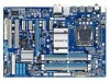
GA-EP45-UD3LR/ GA-EP45-UD3L LGA775 socket motherboard for Intel® CoreTM processor family/ Intel® Pentium® processor family/Intel® Celeron® processor family User's Manual Rev. 1101 12ME-EP45UD3L-1101R
GA-EP45-UD3LR/ GA-EP45-UD3L LGA775 socket motherboard for Intel® CoreTM processor family/ Intel® Pentium® processor family/Intel® Celeron® processor family User's Manual Rev. 1101 12ME-EP45UD3L-1101R
Manual
Page 2
Motherboard GA-EP45-UD3LR/GA-EP45-UD3L Oct. 8, 2008 Motherboard GA-EP45-UD3LR/ GA-EP45-UD3L Oct. 8, 2008
Motherboard GA-EP45-UD3LR/GA-EP45-UD3L Oct. 8, 2008 Motherboard GA-EP45-UD3LR/ GA-EP45-UD3L Oct. 8, 2008

Manual
Page 4
Table of Contents Box Contents ...6 OptionalItems...6 GA-EP45-UD3LR/GA-EP45-UD3L Motherboard Layout 7 Block Diagram...8 Chapter 1 Hardware Installation 9 1-1 Installation Precautions 9 1-2 Product Specifications 10 1-3 Installing the CPU and CPU Cooler 13 1-3-1 Installing the CPU 13 1-3-2 Installing the ...
Table of Contents Box Contents ...6 OptionalItems...6 GA-EP45-UD3LR/GA-EP45-UD3L Motherboard Layout 7 Block Diagram...8 Chapter 1 Hardware Installation 9 1-1 Installation Precautions 9 1-2 Product Specifications 10 1-3 Installing the CPU and CPU Cooler 13 1-3-1 Installing the CPU 13 1-3-2 Installing the ...
Manual
Page 5
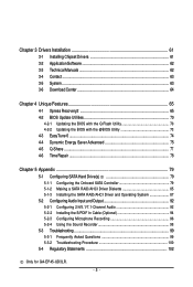
... (Optional 94 5-2-3 Configuring Microphone Recording 96 5-2-4 Using the Sound Recorder 98 5-3 Troubleshooting 99 5-3-1 Frequently Asked Questions 99 5-3-2 Troubleshooting Procedure 100 5-4 Regulatory Statements 102 Only for GA-EP45-UD3LR. - 5 -
... (Optional 94 5-2-3 Configuring Microphone Recording 96 5-2-4 Using the Sound Recorder 98 5-3 Troubleshooting 99 5-3-1 Frequently Asked Questions 99 5-3-2 Troubleshooting Procedure 100 5-4 Regulatory Statements 102 Only for GA-EP45-UD3LR. - 5 -
Manual
Page 6
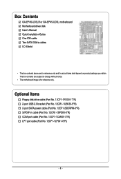
...-1SPDIN-0*R) COM port cable (Part No. 12CF1-1CM001-3*R) LPT port cable (Part No. 12CF1-1LP001-0*R) - 6 - The box contents are for reference only. Box Contents GA-EP45-UD3LR or GA-EP45-UD3L motherboard Motherboard driver disk User's Manual Quick Installation Guide One IDE cable Two SATA 3Gb/s cables I/O Shield • The box contents above are subject to...
...-1SPDIN-0*R) COM port cable (Part No. 12CF1-1CM001-3*R) LPT port cable (Part No. 12CF1-1LP001-0*R) - 6 - The box contents are for reference only. Box Contents GA-EP45-UD3LR or GA-EP45-UD3L motherboard Motherboard driver disk User's Manual Quick Installation Guide One IDE cable Two SATA 3Gb/s cables I/O Shield • The box contents above are subject to...
Manual
Page 7
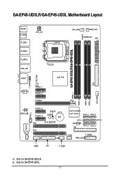
Only for GA-EP45-UD3LR. GA-EP45-UD3LR/GA-EP45-UD3L Motherboard Layout KB_MS R_SPDIF R_USB_1 R_USB_2 R_USB_3 ATX_12V LGA775 CPU_FAN PWR_FAN PHASE LED ATX DDR2_1 GA-EP45-UD3LR/GA-EP45-UD3L DDR2_2 DDR2_3 DDR2_4 FDD SYS_FAN2 USB_LAN F_AUDIO SYS_FAN1 AUDIO Intel® P45 RTL8111C PCIEX1_1 PCIEX1_2 PCIEX16 CODEC SPDIF_O SPDIF_I PCIEX1_3 PCIEX1_4 B_BIOS M_BIOS BAT PCI1 ... CD_IN CI Intel® ICH10R Intel® ICH10 SATA2_3 SATA2_0 SATA2_4 SATA2_ 1 JMicron 368 IDE SATA2_5 SATA2_2 F_USB1 F_PANEL PWR_LED COMA LPT F_USB2 Only for GA-EP45-UD3L. - 7 -
Only for GA-EP45-UD3LR. GA-EP45-UD3LR/GA-EP45-UD3L Motherboard Layout KB_MS R_SPDIF R_USB_1 R_USB_2 R_USB_3 ATX_12V LGA775 CPU_FAN PWR_FAN PHASE LED ATX DDR2_1 GA-EP45-UD3LR/GA-EP45-UD3L DDR2_2 DDR2_3 DDR2_4 FDD SYS_FAN2 USB_LAN F_AUDIO SYS_FAN1 AUDIO Intel® P45 RTL8111C PCIEX1_1 PCIEX1_2 PCIEX16 CODEC SPDIF_O SPDIF_I PCIEX1_3 PCIEX1_4 B_BIOS M_BIOS BAT PCI1 ... CD_IN CI Intel® ICH10R Intel® ICH10 SATA2_3 SATA2_0 SATA2_4 SATA2_ 1 JMicron 368 IDE SATA2_5 SATA2_2 F_USB1 F_PANEL PWR_LED COMA LPT F_USB2 Only for GA-EP45-UD3L. - 7 -
Manual
Page 8
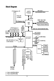
Only for GA-EP45-UD3LR. Block Diagram 1 PCI Express x16 LGA775 Processor CPU CLK+/(400/333/266/200 MHz) PCIe CLK (100 MHz) PCI Express x16 PCIe CLK (100 MHz) 4 ... Speaker Out Center/Subwoofer Speaker Out Side Speaker Out MIC Line-Out Line-In SPDIF In SPDIF Out 2 PCI PCI CLK (33 MHz) Only for GA-EP45-UD3L. - 8 -
Only for GA-EP45-UD3LR. Block Diagram 1 PCI Express x16 LGA775 Processor CPU CLK+/(400/333/266/200 MHz) PCIe CLK (100 MHz) PCI Express x16 PCIe CLK (100 MHz) 4 ... Speaker Out Center/Subwoofer Speaker Out Side Speaker Out MIC Line-Out Line-In SPDIF In SPDIF Out 2 PCI PCI CLK (33 MHz) Only for GA-EP45-UD3L. - 8 -

Manual
Page 10
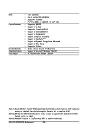
... disk drive connector supporting up to 1 floppy disk drive Integrated in the LGA 775 package (Go to GIGABYTE's website for the latest CPU support list.) L2 cache varies with CPU 1600/1333/1066/800... Dual channel memory architecture Support for DDR2 1366/1066/800/667 MHz memory modules (Go to GIGABYTE's website for the latest memory support list.) Realtek ALC888 codec High Definition Audio ... Bridge: - 6 x SATA 3Gb/s connectors supporting up to the internal USB headers) Only for GA-EP45-UD3LR. Support for GA-EP45-UD3L.
... disk drive connector supporting up to 1 floppy disk drive Integrated in the LGA 775 package (Go to GIGABYTE's website for the latest CPU support list.) L2 cache varies with CPU 1600/1333/1066/800... Dual channel memory architecture Support for DDR2 1366/1066/800/667 MHz memory modules (Go to GIGABYTE's website for the latest memory support list.) Realtek ALC888 codec High Definition Audio ... Bridge: - 6 x SATA 3Gb/s connectors supporting up to the internal USB headers) Only for GA-EP45-UD3LR. Support for GA-EP45-UD3L.
Manual
Page 12
GA-EP45-UD3LR/UD3L Motherboard - 12 - BIOS Unique Features Bundled Software Operating System Form Factor 2 x 8 Mbit flash Use of licensed AWARD BIOS Support for DualBIOSTM ...
GA-EP45-UD3LR/UD3L Motherboard - 12 - BIOS Unique Features Bundled Software Operating System Form Factor 2 x 8 Mbit flash Use of licensed AWARD BIOS Support for DualBIOSTM ...

Manual
Page 14
... raise the CPU socket lever. Follow the steps below to correctly install the CPU into position. Before installing the CPU, make sure to the CPU. GA-EP45-UD3LR/UD3L Motherboard - 14 - Step 2: Lift the metal load plate from the CPU socket. (DO NOT touch socket contacts.) Step 3: Remove the protective socket cover from the...
... raise the CPU socket lever. Follow the steps below to correctly install the CPU into position. Before installing the CPU, make sure to the CPU. GA-EP45-UD3LR/UD3L Motherboard - 14 - Step 2: Lift the metal load plate from the CPU socket. (DO NOT touch socket contacts.) Step 3: Remove the protective socket cover from the...
Manual
Page 16
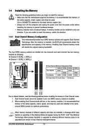
...: Channel 0: DDR2_1, DDR2_2 Channel 1: DDR2_3, DDR2_4 Dual Channel Memory Configurations Table DDR2_1 DDR2_2 DDR2_3 DDR2_4 Two Modules DS/SS - - GA-EP45-UD3LR/UD3L Motherboard - 16 - Enabling Dual Channel memory mode will automatically detect the specifications and capacity of the same capacity, brand, speed, and ... two or four memory modules, it is operating in Dual Channel mode/performance. Dual Channel mode cannot be used . (Go to GIGABYTE's website for optimum performance. It is installed. 2. After the memory is installed, the BIOS will double the original memory bandwidth. ...
...: Channel 0: DDR2_1, DDR2_2 Channel 1: DDR2_3, DDR2_4 Dual Channel Memory Configurations Table DDR2_1 DDR2_2 DDR2_3 DDR2_4 Two Modules DS/SS - - GA-EP45-UD3LR/UD3L Motherboard - 16 - Enabling Dual Channel memory mode will automatically detect the specifications and capacity of the same capacity, brand, speed, and ... two or four memory modules, it is operating in Dual Channel mode/performance. Dual Channel mode cannot be used . (Go to GIGABYTE's website for optimum performance. It is installed. 2. After the memory is installed, the BIOS will double the original memory bandwidth. ...

Manual
Page 18
... Express x16 Slot PCI Slot Follow the steps below to release the card and then pull the card straight up from the chassis back panel. 2. GA-EP45-UD3LR/UD3L Motherboard - 18 - Make sure the card is fully seated in your expansion card. • Always turn off the computer and unplug the power cord from...
... Express x16 Slot PCI Slot Follow the steps below to release the card and then pull the card straight up from the chassis back panel. 2. GA-EP45-UD3LR/UD3L Motherboard - 18 - Make sure the card is fully seated in your expansion card. • Always turn off the computer and unplug the power cord from...
Manual
Page 20
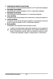
... to perform different functions via the audio software. Line Out Jack (Green) The default line out jack. Use this audio jack for line in jack ( ). GA-EP45-UD3LR/UD3L Motherboard - 20 - Use this audio jack for a headphone or 2-channel speaker. Mic In Jack (Pink) The default Mic in a 5.1/7.1-channel audio configuration. In addition to...
... to perform different functions via the audio software. Line Out Jack (Green) The default line out jack. Use this audio jack for line in jack ( ). GA-EP45-UD3LR/UD3L Motherboard - 20 - Use this audio jack for a headphone or 2-channel speaker. Mic In Jack (Pink) The default Mic in a 5.1/7.1-channel audio configuration. In addition to...
Manual
Page 22
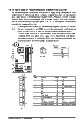
... Definition 3.3V -12V GND PS_ON(soft On/Off) GND GND GND -5V +5V +5V +5V (Only for 2x12-pinATX) GND (Only for 2x12-pin ATX) GA-EP45-UD3LR/UD3L Motherboard - 22 -
... Definition 3.3V -12V GND PS_ON(soft On/Off) GND GND GND -5V +5V +5V +5V (Only for 2x12-pinATX) GND (Only for 2x12-pin ATX) GA-EP45-UD3LR/UD3L Motherboard - 22 -
Manual
Page 24
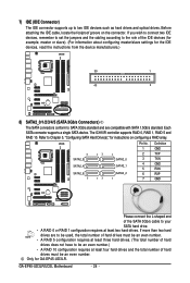
...39 1 40 2 8) SATA2_0/1/2/3/4/5 (SATA 3Gb/s Connectors) The SATA connectors conform to the role of the SATA 3Gb/s cable to be an even number. GA-EP45-UD3LR/UD3L Motherboard - 24 - The ICH10R controller supports RAID 0, RAID 1, RAID 5 and RAID 10. Definition 7 SATA2_3 SATA2_4 SATA2_5 7 17 17 1 SATA2_0 SATA2_1 ...L-shaped end of the IDE devices (for example, master or slave). (For information about configuring master/slave settings for GA-EP45-UD3LR. If more than two hard drives are compatible with SATA 1.5Gb/s standard. Refer to two IDE devices such as hard drives and...
...39 1 40 2 8) SATA2_0/1/2/3/4/5 (SATA 3Gb/s Connectors) The SATA connectors conform to the role of the SATA 3Gb/s cable to be an even number. GA-EP45-UD3LR/UD3L Motherboard - 24 - The ICH10R controller supports RAID 0, RAID 1, RAID 5 and RAID 10. Definition 7 SATA2_3 SATA2_4 SATA2_5 7 17 17 1 SATA2_0 SATA2_1 ...L-shaped end of the IDE devices (for example, master or slave). (For information about configuring master/slave settings for GA-EP45-UD3LR. If more than two hard drives are compatible with SATA 1.5Gb/s standard. Refer to two IDE devices such as hard drives and...
Manual
Page 26
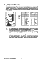
... 6 NC 7 FAUDIO_JD 7 NC 8 No Pin 8 No Pin 9 LINE2_L 9 Line Out (L) 10 GND 10 NC • The front panel audio header supports HD audio by default. GA-EP45-UD3LR/UD3L Motherboard - 26 - For HD Front Panel Audio: For AC'97 Front Panel Audio: Pin No. Definition Pin No. If you want to mute the back...
... 6 NC 7 FAUDIO_JD 7 NC 8 No Pin 8 No Pin 9 LINE2_L 9 Line Out (L) 10 GND 10 NC • The front panel audio header supports HD audio by default. GA-EP45-UD3LR/UD3L Motherboard - 26 - For HD Front Panel Audio: For AC'97 Front Panel Audio: Pin No. Definition Pin No. If you want to mute the back...

Manual
Page 28
Definition 1 Power 2 SPDIFI 3 GND GA-EP45-UD3LR/UD3L Motherboard - 28 - Pin No. Definition 1 CD-L 2 GND 3 GND 4 CD-R 1 13) SPDIF_I (S/PDIF In Heade) This header supports digital S/PDIF in and can connect to the header. 12) CD_IN (CD In Connector) You may connect the audio cable that came with your optical drive to an audio device that supports digital audio out via an optional S/PDIF in cable. For purchasing the optional S/PDIF in cable, please contact the local dealer. 1 Pin No.
Definition 1 Power 2 SPDIFI 3 GND GA-EP45-UD3LR/UD3L Motherboard - 28 - Pin No. Definition 1 CD-L 2 GND 3 GND 4 CD-R 1 13) SPDIF_I (S/PDIF In Heade) This header supports digital S/PDIF in and can connect to the header. 12) CD_IN (CD In Connector) You may connect the audio cable that came with your optical drive to an audio device that supports digital audio out via an optional S/PDIF in cable. For purchasing the optional S/PDIF in cable, please contact the local dealer. 1 Pin No.
Manual
Page 30
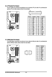
... optional COM port cable, please contact the local dealer. 9 1 10 2 Pin No. 1 2 3 4 5 6 7 8 9 10 Definition NDCD NSIN NSOUT NDTR GND NDSR NRTS NCTS NRI No Pin GA-EP45-UD3LR/UD3L Motherboard - 30 -
... optional COM port cable, please contact the local dealer. 9 1 10 2 Pin No. 1 2 3 4 5 6 7 8 9 10 Definition NDCD NSIN NSOUT NDTR GND NDSR NRTS NCTS NRI No Pin GA-EP45-UD3LR/UD3L Motherboard - 30 -
Manual
Page 32
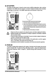
Gently remove the battery from the battery holder and wait for one . Refer to Chapter 4, "Dynamic Energy Saver Advanced," for 5 seconds.) 3. GA-EP45-UD3LR/UD3L Motherboard - 32 - You may be handled in accordance with local environmental regulations. 21) PHASE LED The number of lighted LEDs indicates the CPU loading. Replace ...
Gently remove the battery from the battery holder and wait for one . Refer to Chapter 4, "Dynamic Energy Saver Advanced," for 5 seconds.) 3. GA-EP45-UD3LR/UD3L Motherboard - 32 - You may be handled in accordance with local environmental regulations. 21) PHASE LED The number of lighted LEDs indicates the CPU loading. Replace ...

Manual
Page 34
... key can access Boot Menu again to change the first boot device setting as needed. : Q-FLASH Press the key to accept. Motherboard Model BIOS Version EP45-UD3L E19 . . . . : BIOS Setup : XpressRecovery2 : Boot Menu : Qflash 09/05/2008-P45-ICH10-7A89PG0UC-00 Function Keys Function Keys: : POST SCREEN Press the key to show... the key to enter BIOS Setup or to access the Q-Flash utility in Boot Menu is effective for subsequent access to enter BIOS Setup first. GA-EP45-UD3LR/UD3L Motherboard - 34 - A. The system will still be used for one time only.
... key can access Boot Menu again to change the first boot device setting as needed. : Q-FLASH Press the key to accept. Motherboard Model BIOS Version EP45-UD3L E19 . . . . : BIOS Setup : XpressRecovery2 : Boot Menu : Qflash 09/05/2008-P45-ICH10-7A89PG0UC-00 Function Keys Function Keys: : POST SCREEN Press the key to show... the key to enter BIOS Setup or to access the Q-Flash utility in Boot Menu is effective for subsequent access to enter BIOS Setup first. GA-EP45-UD3LR/UD3L Motherboard - 34 - A. The system will still be used for one time only.


