Manual
Page 3
Disclaimer Information in the use of this product, GIGABYTE provides the following types of documentations: For quick set-up of the product, read the Quick Installation Guide included with the product. For detailed product information, carefully read the User's Manual. For instructions on how to assist in this manual ...
Disclaimer Information in the use of this product, GIGABYTE provides the following types of documentations: For quick set-up of the product, read the Quick Installation Guide included with the product. For detailed product information, carefully read the User's Manual. For instructions on how to assist in this manual ...

Manual
Page 4
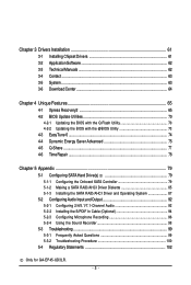
Table of Contents Box Contents ...6 OptionalItems...6 GA-EP45-UD3LR/GA-EP45-UD3L Motherboard Layout 7 Block Diagram...8 Chapter 1 Hardware Installation 9 1-1 Installation Precautions 9 1-2 Product Specifications 10 1-3 Installing the CPU and CPU Cooler 13 1-3-1 Installing the CPU 13 1-3-2 Installing the CPU Cooler 15 1-4 Installing the Memory 16 1-4-1 Dual Channel Memory Configuration 16 1-4-2 Installing a Memory 17 1-5 Installing an Expansion Card 18 1-6 Back Panel Connectors 19 1-7 Internal Connectors 21...
Table of Contents Box Contents ...6 OptionalItems...6 GA-EP45-UD3LR/GA-EP45-UD3L Motherboard Layout 7 Block Diagram...8 Chapter 1 Hardware Installation 9 1-1 Installation Precautions 9 1-2 Product Specifications 10 1-3 Installing the CPU and CPU Cooler 13 1-3-1 Installing the CPU 13 1-3-2 Installing the CPU Cooler 15 1-4 Installing the Memory 16 1-4-1 Dual Channel Memory Configuration 16 1-4-2 Installing a Memory 17 1-5 Installing an Expansion Card 18 1-6 Back Panel Connectors 19 1-7 Internal Connectors 21...
Manual
Page 5
Chapter 3 Drivers Installation 61 3-1 Installing Chipset Drivers 61 3-2 Application Software 62 3-3 Technical Manuals 62 3-4 Contact ...63 3-5 System ...63 3-6 Download ...Installing the SATA RAID/AHCI Driver and Operating System 87 5-2 Configuring Audio Input and Output 92 5-2-1 Configuring 2/4/5.1/7.1-Channel Audio 92 5-2-2 Installing the S/PDIF In Cable (Optional 94 5-2-3 Configuring Microphone Recording 96 5-2-4 Using the Sound Recorder 98 5-3 Troubleshooting 99 5-3-1 Frequently Asked Questions 99 5-3-2 Troubleshooting Procedure 100 5-4 Regulatory Statements 102 Only for GA-EP45...
Chapter 3 Drivers Installation 61 3-1 Installing Chipset Drivers 61 3-2 Application Software 62 3-3 Technical Manuals 62 3-4 Contact ...63 3-5 System ...63 3-6 Download ...Installing the SATA RAID/AHCI Driver and Operating System 87 5-2 Configuring Audio Input and Output 92 5-2-1 Configuring 2/4/5.1/7.1-Channel Audio 92 5-2-2 Installing the S/PDIF In Cable (Optional 94 5-2-3 Configuring Microphone Recording 96 5-2-4 Using the Sound Recorder 98 5-3 Troubleshooting 99 5-3-1 Frequently Asked Questions 99 5-3-2 Troubleshooting Procedure 100 5-4 Regulatory Statements 102 Only for GA-EP45...
Manual
Page 6
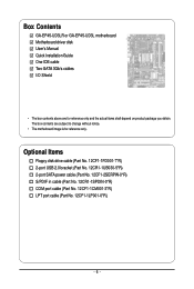
... (Part No. 12CF1-1CM001-3*R) LPT port cable (Part No. 12CF1-1LP001-0*R) - 6 - The box contents are for reference only. Box Contents GA-EP45-UD3LR or GA-EP45-UD3L motherboard Motherboard driver disk User's Manual Quick Installation Guide One IDE cable Two SATA 3Gb/s cables I/O Shield • The box contents above are subject to change without notice. •...
... (Part No. 12CF1-1CM001-3*R) LPT port cable (Part No. 12CF1-1LP001-0*R) - 6 - The box contents are for reference only. Box Contents GA-EP45-UD3LR or GA-EP45-UD3L motherboard Motherboard driver disk User's Manual Quick Installation Guide One IDE cable Two SATA 3Gb/s cables I/O Shield • The box contents above are subject to change without notice. •...
Manual
Page 9
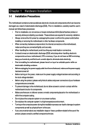
...not have an ESD wrist strap, keep your hands dry and first touch a metal object to eliminate static electricity. • Prior to installing the motherboard, please have it on top of an antistatic pad or within the computer casing. • Do not place the computer system... placed on the motherboard or within an electrostatic shielding container. • Before unplugging the power supply cable from the power outlet before installing or removing the motherboard or other hardware components. • When connecting hardware components to the internal connectors on the motherboard, make sure...
...not have an ESD wrist strap, keep your hands dry and first touch a metal object to eliminate static electricity. • Prior to installing the motherboard, please have it on top of an antistatic pad or within the computer casing. • Do not place the computer system... placed on the motherboard or within an electrostatic shielding container. • Before unplugging the power supply cable from the power outlet before installing or removing the motherboard or other hardware components. • When connecting hardware components to the internal connectors on the motherboard, make sure...
Manual
Page 11
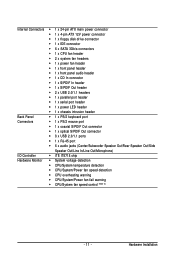
.../System/Power fan speed detection CPU overheating warning CPU/System/Power fan fail warning CPU/System fan speed control (Note 2) - 11 - Hardware Installation
.../System/Power fan speed detection CPU overheating warning CPU/System/Power fan fail warning CPU/System fan speed control (Note 2) - 11 - Hardware Installation
Manual
Page 12
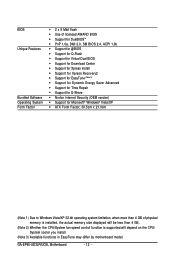
...for @BIOS Support for Q-Flash Support for Virtual Dual BIOS Support for Download Center Support for Xpress Install Support for Xpress Recovery2 Support for EasyTune (Note 3) Support for Dynamic Energy Saver Advanced Support for...is installed, the actual memory size displayed will be less than 4 GB. (Note 2) Whether the CPU/System fan speed control function is supported will depend on the CPU/ System cooler you install. (Note 3) Available functions in EasyTune may differ by motherboard model. GA-EP45-UD3LR/UD3L Motherboard...
...for @BIOS Support for Q-Flash Support for Virtual Dual BIOS Support for Download Center Support for Xpress Install Support for Xpress Recovery2 Support for EasyTune (Note 3) Support for Dynamic Energy Saver Advanced Support for...is installed, the actual memory size displayed will be less than 4 GB. (Note 2) Whether the CPU/System fan speed control function is supported will depend on the CPU/ System cooler you install. (Note 3) Available functions in EasyTune may differ by motherboard model. GA-EP45-UD3LR/UD3L Motherboard...
Manual
Page 13
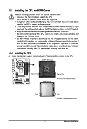
mended that the motherboard supports the CPU. (Go to GIGABYTE's website for the peripherals. Hardware Installation The CPU cannot be set the frequency beyond hardware specifications since it does not meet the standard requirements for the latest CPU support list.) • ... the surface of the CPU. • Do not turn off the computer and unplug the power cord from the power outlet before you begin to install the CPU: • Make sure that the system bus frequency be inserted if oriented incorrectly. (Or you wish to set beyond the standard specifications, please...
mended that the motherboard supports the CPU. (Go to GIGABYTE's website for the peripherals. Hardware Installation The CPU cannot be set the frequency beyond hardware specifications since it does not meet the standard requirements for the latest CPU support list.) • ... the surface of the CPU. • Do not turn off the computer and unplug the power cord from the power outlet before you begin to install the CPU: • Make sure that the system bus frequency be inserted if oriented incorrectly. (Or you wish to set beyond the standard specifications, please...

Manual
Page 14
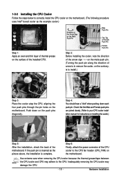
... notches with your thumb and index fingers. CPU Socket Lever Step 1: Completely raise the CPU socket lever. GA-EP45-UD3LR/UD3L Motherboard - 14 - Follow the steps below to correctly install the CPU into its locked position. Before installing the CPU, make sure to the CPU. Step 2: Lift the metal load plate from the CPU socket... is properly inserted, replace the load plate and push the CPU socket lever back into the motherboard CPU socket. B. Step 5: Once the CPU is not installed.) Step 4: Hold the CPU with the socket alignment keys) and gently insert the CPU into position.
... notches with your thumb and index fingers. CPU Socket Lever Step 1: Completely raise the CPU socket lever. GA-EP45-UD3LR/UD3L Motherboard - 14 - Follow the steps below to correctly install the CPU into its locked position. Before installing the CPU, make sure to the CPU. Step 2: Lift the metal load plate from the CPU socket... is properly inserted, replace the load plate and push the CPU socket lever back into the motherboard CPU socket. B. Step 5: Once the CPU is not installed.) Step 4: Hold the CPU with the socket alignment keys) and gently insert the CPU into position.
Manual
Page 15
...motherboard. Direction of the Arrow Sign on the Male Push Pin Male Push Pin The Top of Female Push Pin Female Push Pin Step 2: Before installing the cooler, note the direction of the arrow sign on the male push pin. (Turning the push pin along the direction of the motherboard. ...the back of arrow is to remove the cooler, on the contrary, is complete. Inadequately removing the CPU cooler may adhere to the CPU. Hardware Installation Use extreme care when removing the CPU cooler because the thermal grease/tape between the CPU cooler and CPU may damage the CPU. - 15 - ...
...motherboard. Direction of the Arrow Sign on the Male Push Pin Male Push Pin The Top of Female Push Pin Female Push Pin Step 2: Before installing the cooler, note the direction of the arrow sign on the male push pin. (Turning the push pin along the direction of the motherboard. ...the back of arrow is to remove the cooler, on the contrary, is complete. Inadequately removing the CPU cooler may adhere to the CPU. Hardware Installation Use extreme care when removing the CPU cooler because the thermal grease/tape between the CPU cooler and CPU may damage the CPU. - 15 - ...
Manual
Page 16
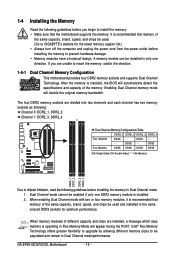
...When enabling Dual Channel mode with two or four memory modules, it is recommended that the motherboard supports the memory. GA-EP45-UD3LR/UD3L Motherboard - 16 - 1-4 Installing the Memory Read the following guidelines before you are divided into two channels and each channel has two memory sockets as ...DS/SS (SS=Single-Sided, DS=Double-Sided, "- -"=No Memory) DDR2_1 DDR2_2 DDR2_3 DDR2_4 Due to GIGABYTE's website for optimum performance. A memory module can be used and installed in the same colored DDR2 sockets for the latest memory support list.) • Always turn off the ...
...When enabling Dual Channel mode with two or four memory modules, it is recommended that the motherboard supports the memory. GA-EP45-UD3LR/UD3L Motherboard - 16 - 1-4 Installing the Memory Read the following guidelines before you are divided into two channels and each channel has two memory sockets as ...DS/SS (SS=Single-Sided, DS=Double-Sided, "- -"=No Memory) DDR2_1 DDR2_2 DDR2_3 DDR2_4 Due to GIGABYTE's website for optimum performance. A memory module can be used and installed in the same colored DDR2 sockets for the latest memory support list.) • Always turn off the ...
Manual
Page 17
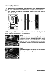
DDR2 DIMMs are not compatible to DDR DIMMs. Be sure to install DDR2 DIMMs on the socket. Notch DDR2 DIMM A DDR2 memory module has a notch, so it vertically into place when the memory module is securely inserted. - ... and insert it can only fit in the memory sockets. As indicated in the picture on the left, place your memory modules in one direction. 1-4-2 Installing a Memory Before installing a memory module , make sure to turn off the computer and unplug the power cord from the power outlet to prevent damage to correctly...
DDR2 DIMMs are not compatible to DDR DIMMs. Be sure to install DDR2 DIMMs on the socket. Notch DDR2 DIMM A DDR2 memory module has a notch, so it vertically into place when the memory module is securely inserted. - ... and insert it can only fit in the memory sockets. As indicated in the picture on the left, place your memory modules in one direction. 1-4-2 Installing a Memory Before installing a memory module , make sure to turn off the computer and unplug the power cord from the power outlet to prevent damage to correctly...

Manual
Page 18
..., and press down on your card. Make sure the card is securely seated in the slot. 3. 1-5 Installing an Expansion Card Read the following guidelines before installing an expansion card to the chassis back panel with your expansion card(s). 7. Carefully read the manual that supports ...your expansion card. • Always turn off the computer and unplug the power cord from the chassis back panel. 2. GA-EP45-UD3LR/UD3L Motherboard - 18 - After installing all expansion cards, replace the chassis cover(s). 6. Remove the metal slot cover from the power outlet before you begin to...
..., and press down on your card. Make sure the card is securely seated in the slot. 3. 1-5 Installing an Expansion Card Read the following guidelines before installing an expansion card to the chassis back panel with your expansion card(s). 7. Carefully read the manual that supports ...your expansion card. • Always turn off the computer and unplug the power cord from the chassis back panel. 2. GA-EP45-UD3LR/UD3L Motherboard - 18 - After installing all expansion cards, replace the chassis cover(s). 6. Remove the metal slot cover from the power outlet before you begin to...
Manual
Page 19
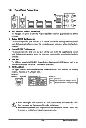
... audio system that supports digital coaxial audio. Do not rock it straight out from your audio system provides an optical digital audio in connector. Hardware Installation Use this feature, ensure that your device and then remove it from the motherboard. • When removing the cable, pull it side to side to...
... audio system that supports digital coaxial audio. Do not rock it straight out from your audio system provides an optical digital audio in connector. Hardware Installation Use this feature, ensure that your device and then remove it from the motherboard. • When removing the cable, pull it side to side to...

Manual
Page 21
... the power cord from the power outlet to prevent damage to the devices. • After installing the device and before connecting external devices: • First make sure the device cable has ...been securely attached to turn off the devices and your devices are compliant with the connectors you wish to connect. • Before installing the devices, be sure to the connector on the motherboard. - 21 - 1-7 Internal Connectors 1 35 21 2 10 6 4 4 19...) PHASE LED Read the following guidelines before turning on the computer, make sure your computer. Hardware Installation
... the power cord from the power outlet to prevent damage to the devices. • After installing the device and before connecting external devices: • First make sure the device cable has ...been securely attached to turn off the devices and your devices are compliant with the connectors you wish to connect. • Before installing the devices, be sure to the connector on the motherboard. - 21 - 1-7 Internal Connectors 1 35 21 2 10 6 4 4 19...) PHASE LED Read the following guidelines before turning on the computer, make sure your computer. Hardware Installation
Manual
Page 22
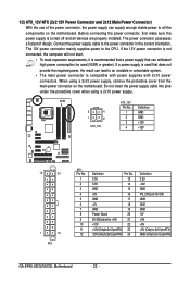
... and 2x12 Main Power Connector) With the use of the power connector, the power supply can supply enough stable power to all devices are properly installed. When using a 2x10 power supply. 3 4 1 2 ATX_12V ATX_12V : Pin No. 1 2 3 4 Definition GND GND +12V +12V 12 24 1 13 ATX ATX: Pin No. 1 2 3 4 5 6...(soft On/Off) GND GND GND -5V +5V +5V +5V (Only for 2x12-pinATX) GND (Only for 2x12-pin ATX) GA-EP45-UD3LR/UD3L Motherboard - 22 - The power connector possesses a foolproof design. The 12V power connector mainly supplies power to the power connector in the correct orientation...
... and 2x12 Main Power Connector) With the use of the power connector, the power supply can supply enough stable power to all devices are properly installed. When using a 2x10 power supply. 3 4 1 2 ATX_12V ATX_12V : Pin No. 1 2 3 4 Definition GND GND +12V +12V 12 24 1 13 ATX ATX: Pin No. 1 2 3 4 5 6...(soft On/Off) GND GND GND -5V +5V +5V +5V (Only for 2x12-pinATX) GND (Only for 2x12-pin ATX) GA-EP45-UD3LR/UD3L Motherboard - 22 - The power connector possesses a foolproof design. The 12V power connector mainly supplies power to the power connector in the correct orientation...

Manual
Page 23
... locate pin 1 of floppy disk drives supported are not configuration jumper blocks. Most fan headers possess a foolproof insertion design. Before connecting a floppy disk drive, be installed inside the chassis. 1 CPU_FAN CPU_FAN: Pin No. 1 2 3 Definition GND Speed Control Sense 4 Speed Control SYS_FAN2: Pin No. 1 Definition GND 1 SYS_FAN2 2 Speed Control 3 Sense 4 +5V 1 SYS_FAN1... (SYS_FAN1) and a 4-pin (SYS_FAN2) system fan headers, and a 3-pin power fan header (PWR_FAN). The types of the connector and the floppy disk drive cable. Hardware Installation
... locate pin 1 of floppy disk drives supported are not configuration jumper blocks. Most fan headers possess a foolproof insertion design. Before connecting a floppy disk drive, be installed inside the chassis. 1 CPU_FAN CPU_FAN: Pin No. 1 2 3 Definition GND Speed Control Sense 4 Speed Control SYS_FAN2: Pin No. 1 Definition GND 1 SYS_FAN2 2 Speed Control 3 Sense 4 +5V 1 SYS_FAN1... (SYS_FAN1) and a 4-pin (SYS_FAN2) system fan headers, and a 3-pin power fan header (PWR_FAN). The types of the connector and the floppy disk drive cable. Hardware Installation
Manual
Page 25
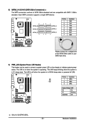
System Status LED S0 On S1 Blinking S3/S4/S5 Off Only for GA-EP45-UD3L. - 25 - Pin No. The LED is in S1 sleep state. The LED is off (S5). Hardware Installation Each SATA connector supports a single SATA device. 7 SATA2_3 SATA2_4 SATA2_5 7 17 17 1 SATA2_0 SATA2_1 SATA2_2 1 Pin No. 1 2 3 4 5 6 7 Definition GND TXP TXN GND...
System Status LED S0 On S1 Blinking S3/S4/S5 Off Only for GA-EP45-UD3L. - 25 - Pin No. The LED is in S1 sleep state. The LED is off (S5). Hardware Installation Each SATA connector supports a single SATA device. 7 SATA2_3 SATA2_4 SATA2_5 7 17 17 1 SATA2_0 SATA2_1 SATA2_2 1 Pin No. 1 2 3 4 5 6 7 Definition GND TXP TXN GND...

Manual
Page 27
... to indicate the problem. If a problem is in different patterns to this header according to the power status indicator on the chassis front panel. Hardware Installation The LED keeps blinking when S1 Blinking the system is detected, the BIOS may issue beeps in S1 sleep state. You may differ by issuing...
... to indicate the problem. If a problem is in different patterns to this header according to the power status indicator on the chassis front panel. Hardware Installation The LED keeps blinking when S1 Blinking the system is detected, the BIOS may issue beeps in S1 sleep state. You may differ by issuing...

Manual
Page 29
...+ USB DY+ GND GND No Pin NC • Do not plug the IEEE 1394 bracket (2x5-pin) cable into the USB header. • Prior to installing the USB bracket, be sure to turn off your graphics card if you to use a S/PDIF digital audio cable for digital audio output from your... your expansion card. For information about connecting the S/PDIF digital audio cable, carefully read the manual for your motherboard to USB 2.0/1.1 specification. Pin No. Hardware Installation
...+ USB DY+ GND GND No Pin NC • Do not plug the IEEE 1394 bracket (2x5-pin) cable into the USB header. • Prior to installing the USB bracket, be sure to turn off your graphics card if you to use a S/PDIF digital audio cable for digital audio output from your... your expansion card. For information about connecting the S/PDIF digital audio cable, carefully read the manual for your motherboard to USB 2.0/1.1 specification. Pin No. Hardware Installation


