Manual
Page 1
GA-EP45-UD3LR/ GA-EP45-UD3L LGA775 socket motherboard for Intel® CoreTM processor family/ Intel® Pentium® processor family/Intel® Celeron® processor family User's Manual Rev. 1101 12ME-EP45UD3L-1101R
GA-EP45-UD3LR/ GA-EP45-UD3L LGA775 socket motherboard for Intel® CoreTM processor family/ Intel® Pentium® processor family/Intel® Celeron® processor family User's Manual Rev. 1101 12ME-EP45UD3L-1101R
Manual
Page 2
Motherboard GA-EP45-UD3LR/GA-EP45-UD3L Oct. 8, 2008 Motherboard GA-EP45-UD3LR/ GA-EP45-UD3L Oct. 8, 2008
Motherboard GA-EP45-UD3LR/GA-EP45-UD3L Oct. 8, 2008 Motherboard GA-EP45-UD3LR/ GA-EP45-UD3L Oct. 8, 2008
Manual
Page 3
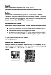
...TECHNOLOGY CO., LTD. All rights reserved. Example: For product-related information, check on our website at: http://www.gigabyte.com.tw Identifying Your Motherboard Revision The revision number on our website. Documentation Classifications In order to assist in this : "REV: X.X." For example...read or download the information on/from the Support\Motherboard\Technology Guide page on your motherboard revision before updating motherboard BIOS, drivers, or when looking for technical information. The trademarks mentioned in the use GIGABYTE's unique features, read the User's Manual. &#...
...TECHNOLOGY CO., LTD. All rights reserved. Example: For product-related information, check on our website at: http://www.gigabyte.com.tw Identifying Your Motherboard Revision The revision number on our website. Documentation Classifications In order to assist in this : "REV: X.X." For example...read or download the information on/from the Support\Motherboard\Technology Guide page on your motherboard revision before updating motherboard BIOS, drivers, or when looking for technical information. The trademarks mentioned in the use GIGABYTE's unique features, read the User's Manual. &#...

Manual
Page 4
Table of Contents Box Contents ...6 OptionalItems...6 GA-EP45-UD3LR/GA-EP45-UD3L Motherboard Layout 7 Block Diagram...8 Chapter 1 Hardware Installation 9 1-1 Installation Precautions 9 1-2 Product Specifications 10 1-3 Installing the CPU and CPU Cooler 13 1-3-1 Installing the CPU 13 1-3-2 Installing the CPU ...
Table of Contents Box Contents ...6 OptionalItems...6 GA-EP45-UD3LR/GA-EP45-UD3L Motherboard Layout 7 Block Diagram...8 Chapter 1 Hardware Installation 9 1-1 Installation Precautions 9 1-2 Product Specifications 10 1-3 Installing the CPU and CPU Cooler 13 1-3-1 Installing the CPU 13 1-3-2 Installing the CPU ...
Manual
Page 6
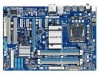
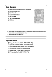
...12CR1-1SPDIN-0*R) COM port cable (Part No. 12CF1-1CM001-3*R) LPT port cable (Part No. 12CF1-1LP001-0*R) - 6 - Box Contents GA-EP45-UD3LR or GA-EP45-UD3L motherboard Motherboard driver disk User's Manual Quick Installation Guide One IDE cable Two SATA 3Gb/s cables I/O Shield • The box contents above are... subject to change without notice. • The motherboard image is for reference only and the actual items shall...
...12CR1-1SPDIN-0*R) COM port cable (Part No. 12CF1-1CM001-3*R) LPT port cable (Part No. 12CF1-1LP001-0*R) - 6 - Box Contents GA-EP45-UD3LR or GA-EP45-UD3L motherboard Motherboard driver disk User's Manual Quick Installation Guide One IDE cable Two SATA 3Gb/s cables I/O Shield • The box contents above are... subject to change without notice. • The motherboard image is for reference only and the actual items shall...
Manual
Page 7
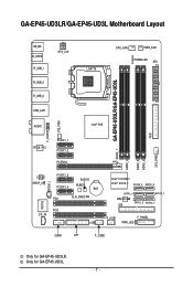
GA-EP45-UD3LR/GA-EP45-UD3L Motherboard Layout KB_MS R_SPDIF R_USB_1 R_USB_2 R_USB_3 ATX_12V LGA775 CPU_FAN PWR_FAN PHASE LED ATX DDR2_1 GA-EP45-UD3LR/GA-EP45-UD3L DDR2_2 DDR2_3 DDR2_4 FDD SYS_FAN2 USB_LAN F_AUDIO SYS_FAN1 AUDIO Intel® P45 RTL8111C PCIEX1_1 PCIEX1_2 PCIEX16 CODEC SPDIF_O SPDIF_I PCIEX1_3 PCIEX1_4 B_BIOS M_BIOS BAT PCI1 ... CD_IN CI Intel® ICH10R Intel® ICH10 SATA2_3 SATA2_0 SATA2_4 SATA2_ 1 JMicron 368 IDE SATA2_5 SATA2_2 F_USB1 F_PANEL PWR_LED COMA LPT F_USB2 Only for GA-EP45-UD3L. - 7 - Only for GA-EP45-UD3LR.
GA-EP45-UD3LR/GA-EP45-UD3L Motherboard Layout KB_MS R_SPDIF R_USB_1 R_USB_2 R_USB_3 ATX_12V LGA775 CPU_FAN PWR_FAN PHASE LED ATX DDR2_1 GA-EP45-UD3LR/GA-EP45-UD3L DDR2_2 DDR2_3 DDR2_4 FDD SYS_FAN2 USB_LAN F_AUDIO SYS_FAN1 AUDIO Intel® P45 RTL8111C PCIEX1_1 PCIEX1_2 PCIEX16 CODEC SPDIF_O SPDIF_I PCIEX1_3 PCIEX1_4 B_BIOS M_BIOS BAT PCI1 ... CD_IN CI Intel® ICH10R Intel® ICH10 SATA2_3 SATA2_0 SATA2_4 SATA2_ 1 JMicron 368 IDE SATA2_5 SATA2_2 F_USB1 F_PANEL PWR_LED COMA LPT F_USB2 Only for GA-EP45-UD3L. - 7 - Only for GA-EP45-UD3LR.
Manual
Page 9
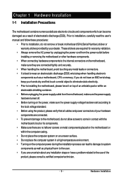
...best to the use of the product, please consult a certified computer technician. - 9 - Chapter 1 Hardware Installation 1-1 Installation Precautions The motherboard contains numerous delicate electronic circuits and components which can lead to damage to system components as well as physical harm to the user. &#... wrist strap, keep your hands dry and first touch a metal object to eliminate static electricity. • Prior to installing the motherboard, please have a problem related to wear an electrostatic discharge (ESD) wrist strap when handling electronic components such as a result of...
...best to the use of the product, please consult a certified computer technician. - 9 - Chapter 1 Hardware Installation 1-1 Installation Precautions The motherboard contains numerous delicate electronic circuits and components which can lead to damage to system components as well as physical harm to the user. &#... wrist strap, keep your hands dry and first touch a metal object to eliminate static electricity. • Prior to installing the motherboard, please have a problem related to wear an electrostatic discharge (ESD) wrist strap when handling electronic components such as a result of...

Manual
Page 10
...61559; Up to 12 USB 2.0/1.1 ports (8 on the back panel, 4 via the USB brackets connected to the internal USB headers) Only for GA-EP45-UD3LR. Only for CD In 1 x Realtek 8111C chip (10/100/1000 Mbit) 1 x PCI Express x16 slot, ... South Bridge: Intel® ICH10R /ICH10 4 x 1.8V DDR2 DIMM sockets supporting up to GIGABYTE's website for the latest memory support list.) Realtek ALC888 codec High Definition Audio 2/4/5.1/7.1-channel Support for S/PDIF In/Out Support for GA-EP45-UD3L. GA-EP45-UD3LR/UD3L Motherboard - 10 -
...61559; Up to 12 USB 2.0/1.1 ports (8 on the back panel, 4 via the USB brackets connected to the internal USB headers) Only for GA-EP45-UD3LR. Only for CD In 1 x Realtek 8111C chip (10/100/1000 Mbit) 1 x PCI Express x16 slot, ... South Bridge: Intel® ICH10R /ICH10 4 x 1.8V DDR2 DIMM sockets supporting up to GIGABYTE's website for the latest memory support list.) Realtek ALC888 codec High Definition Audio 2/4/5.1/7.1-channel Support for S/PDIF In/Out Support for GA-EP45-UD3L. GA-EP45-UD3LR/UD3L Motherboard - 10 -
Manual
Page 12
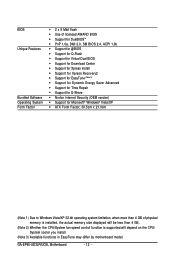
GA-EP45-UD3LR/UD3L Motherboard - 12 - BIOS Unique Features Bundled Software Operating System Form Factor 2 x 8 Mbit flash Use of licensed AWARD BIOS Support for DualBIOSTM PnP 1.... CPU/System fan speed control function is supported will depend on the CPU/ System cooler you install. (Note 3) Available functions in EasyTune may differ by motherboard model.
GA-EP45-UD3LR/UD3L Motherboard - 12 - BIOS Unique Features Bundled Software Operating System Form Factor 2 x 8 Mbit flash Use of licensed AWARD BIOS Support for DualBIOSTM PnP 1.... CPU/System fan speed control function is supported will depend on the CPU/ System cooler you install. (Note 3) Available functions in EasyTune may differ by motherboard model.
Manual
Page 13
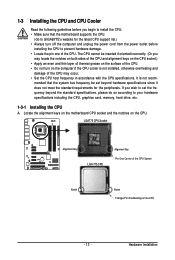
...specifications including the CPU, graphics card, memory, hard drive, etc. 1-3-1 Installing the CPU A. Hardware Installation Locate the alignment keys on the motherboard CPU socket and the notches on the computer if the CPU cooler is not recom- LGA775 CPU Socket Alignment Key LGA 775 CPU Alignment ...; Locate the pin one of the CPU Socket Notch Notch Triangle Pin One Marking on the CPU - 13 - mended that the motherboard supports the CPU. (Go to GIGABYTE's website for the peripherals. 1-3 Installing the CPU and CPU Cooler Read the following guidelines before you begin to install the CPU: ...
...specifications including the CPU, graphics card, memory, hard drive, etc. 1-3-1 Installing the CPU A. Hardware Installation Locate the alignment keys on the motherboard CPU socket and the notches on the computer if the CPU cooler is not recom- LGA775 CPU Socket Alignment Key LGA 775 CPU Alignment ...; Locate the pin one of the CPU Socket Notch Notch Triangle Pin One Marking on the CPU - 13 - mended that the motherboard supports the CPU. (Go to GIGABYTE's website for the peripherals. 1-3 Installing the CPU and CPU Cooler Read the following guidelines before you begin to install the CPU: ...

Manual
Page 14
.... (DO NOT touch socket contacts.) Step 3: Remove the protective socket cover from the power outlet to prevent damage to correctly install the CPU into the motherboard CPU socket. Follow the steps below to the CPU. GA-EP45-UD3LR/UD3L Motherboard - 14 - B.
.... (DO NOT touch socket contacts.) Step 3: Remove the protective socket cover from the power outlet to prevent damage to correctly install the CPU into the motherboard CPU socket. Follow the steps below to the CPU. GA-EP45-UD3LR/UD3L Motherboard - 14 - B.
Manual
Page 15
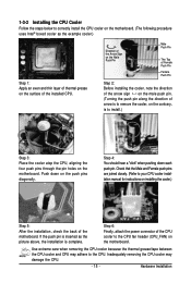
...removing the CPU cooler may adhere to the CPU. 1-3-2 Installing the CPU Cooler Follow the steps below to correctly install the CPU cooler on the motherboard. (The following procedure uses Intel® boxed cooler as the picture above, the installation is to install.) Step 3: Place the cooler atop the... CPU, aligning the four push pins through the pin holes on the motherboard. Hardware Installation Use extreme care when removing the CPU cooler because the thermal grease/tape between the CPU cooler and CPU may damage the ...
...removing the CPU cooler may adhere to the CPU. 1-3-2 Installing the CPU Cooler Follow the steps below to correctly install the CPU cooler on the motherboard. (The following procedure uses Intel® boxed cooler as the picture above, the installation is to install.) Step 3: Place the cooler atop the... CPU, aligning the four push pins through the pin holes on the motherboard. Hardware Installation Use extreme care when removing the CPU cooler because the thermal grease/tape between the CPU cooler and CPU may damage the ...
Manual
Page 16
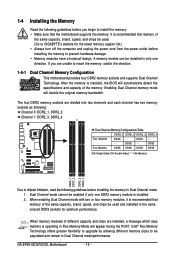
... enabled if only one direction. 1-4 Installing the Memory Read the following guidelines before you are installed, a message which says memory is installed. 2. GA-EP45-UD3LR/UD3L Motherboard - 16 - It is recommended that the motherboard supports the memory. DS/SS - - - - When enabling Dual Channel mode with two or four memory modules, it is recommended that memory... will appear during the POST. If you begin to prevent hardware damage. • Memory modules have a foolproof design. A memory module can be used . (Go to GIGABYTE's website for optimum performance.
... enabled if only one direction. 1-4 Installing the Memory Read the following guidelines before you are installed, a message which says memory is installed. 2. GA-EP45-UD3LR/UD3L Motherboard - 16 - It is recommended that the motherboard supports the memory. DS/SS - - - - When enabling Dual Channel mode with two or four memory modules, it is recommended that memory... will appear during the POST. If you begin to prevent hardware damage. • Memory modules have a foolproof design. A memory module can be used . (Go to GIGABYTE's website for optimum performance.
Manual
Page 17
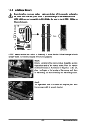
Follow the steps below to the memory module. Place the memory module on this motherboard. 1-4-2 Installing a Memory Before installing a memory module , make sure to turn off the computer and unplug the power cord from the power outlet to prevent damage ...
Follow the steps below to the memory module. Place the memory module on this motherboard. 1-4-2 Installing a Memory Before installing a memory module , make sure to turn off the computer and unplug the power cord from the power outlet to prevent damage ...

Manual
Page 18
... computer and unplug the power cord from the power outlet before you begin to install an expansion card: • Make sure the motherboard supports the expansion card. Locate an expansion slot that came with the slot, and press down on the card are completely inserted into...not rock. • Removing the Card: Press the white latch at the end of the card until it is fully inserted into the slot. 4. GA-EP45-UD3LR/UD3L Motherboard - 18 - Turn on the card until it is securely seated in your expansion card(s). 7. Install the driver provided with a screw. 5. After...
... computer and unplug the power cord from the power outlet before you begin to install an expansion card: • Make sure the motherboard supports the expansion card. Locate an expansion slot that came with the slot, and press down on the card are completely inserted into...not rock. • Removing the Card: Press the white latch at the end of the card until it is fully inserted into the slot. 4. GA-EP45-UD3LR/UD3L Motherboard - 18 - Turn on the card until it is securely seated in your expansion card(s). 7. Install the driver provided with a screw. 5. After...
Manual
Page 19
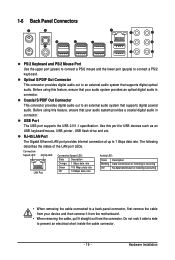
... a back panel connector, first remove the cable from your audio system provides a coaxial digital audio in connector. Do not rock it straight out from the motherboard. • When removing the cable, pull it side to side to an external audio system that supports digital optical audio. Use this feature, ensure that...
... a back panel connector, first remove the cable from your audio system provides a coaxial digital audio in connector. Do not rock it straight out from the motherboard. • When removing the cable, pull it side to side to an external audio system that supports digital optical audio. Use this feature, ensure that...
Manual
Page 20
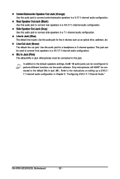
.... This jack can be used to connect side speakers in Chapter 5, "Configuring 2/4/5.1/7.1-Channel Audio." Mic In Jack (Pink) The default Mic in a 4/5.1/7.1-channel audio configuration. GA-EP45-UD3LR/UD3L Motherboard - 20 - Rear Speaker Out Jack (Black) Use this jack.
.... This jack can be used to connect side speakers in Chapter 5, "Configuring 2/4/5.1/7.1-Channel Audio." Mic In Jack (Pink) The default Mic in a 4/5.1/7.1-channel audio configuration. GA-EP45-UD3LR/UD3L Motherboard - 20 - Rear Speaker Out Jack (Black) Use this jack.

Manual
Page 21
...) SPDIF_O 15) F_USB1/F_USB2 16) LPT 17) COMA 18) CI 19) CLR_CMOS 20) BAT 21) PHASE LED Read the following guidelines before turning on the motherboard. - 21 - Hardware Installation Unplug the power cord from the power outlet to prevent damage to the devices. • After installing the device and before connecting...
...) SPDIF_O 15) F_USB1/F_USB2 16) LPT 17) COMA 18) CI 19) CLR_CMOS 20) BAT 21) PHASE LED Read the following guidelines before turning on the motherboard. - 21 - Hardware Installation Unplug the power cord from the power outlet to prevent damage to the devices. • After installing the device and before connecting...
Manual
Page 22
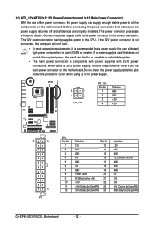
... the power connector, first make sure the power supply is turned off and all the components on the motherboard. If the 12V power connector is not connected, the computer will not start. • To meet expansion...pins under the protective cover when using a 2x12 power supply, remove the protective cover from the main power connector on the motherboard. Connect the power supply cable to the CPU. If a power supply is compatible with power supplies with 2x10 power connectors...GND GND -5V +5V +5V +5V (Only for 2x12-pinATX) GND (Only for 2x12-pin ATX) GA-EP45-UD3LR/UD3L Motherboard - 22 -
... the power connector, first make sure the power supply is turned off and all the components on the motherboard. If the 12V power connector is not connected, the computer will not start. • To meet expansion...pins under the protective cover when using a 2x12 power supply, remove the protective cover from the main power connector on the motherboard. Connect the power supply cable to the CPU. If a power supply is compatible with power supplies with 2x10 power connectors...GND GND -5V +5V +5V +5V (Only for 2x12-pinATX) GND (Only for 2x12-pin ATX) GA-EP45-UD3LR/UD3L Motherboard - 22 -

Manual
Page 23
... 2 +12V 3 Sense • Be sure to connect fan cables to the fan headers to connect a floppy disk drive. The motherboard supports CPU fan speed control, which requires the use of floppy disk drives supported are not configuration jumper blocks. For optimum heat dissipation..., it in damage to locate pin 1 of different color. 34 33 2 1 - 23 - 3/4/5) CPU_FAN/SYS_FAN1/SYS_FAN2/PWR_FAN (Fan Headers) The motherboard has a 4-pin CPU fan header (CPU_FAN), a 3-pin (SYS_FAN1) and a 4-pin (SYS_FAN2) system fan headers, and a 3-pin power fan header (PWR_FAN)....
... 2 +12V 3 Sense • Be sure to connect fan cables to the fan headers to connect a floppy disk drive. The motherboard supports CPU fan speed control, which requires the use of floppy disk drives supported are not configuration jumper blocks. For optimum heat dissipation..., it in damage to locate pin 1 of different color. 34 33 2 1 - 23 - 3/4/5) CPU_FAN/SYS_FAN1/SYS_FAN2/PWR_FAN (Fan Headers) The motherboard has a 4-pin CPU fan header (CPU_FAN), a 3-pin (SYS_FAN1) and a 4-pin (SYS_FAN2) system fan headers, and a 3-pin power fan header (PWR_FAN)....


