
Manual
Page 4
Table of Contents Box Contents ...6 OptionalItems...6 GA-EP45-UD3LR/GA-EP45-UD3L Motherboard Layout 7 Block Diagram...8 Chapter 1 Hardware Installation 9 1-1 Installation Precautions 9 1-2 Product Specifications 10 1-3 Installing the CPU and CPU Cooler 13 1-3-1 ... Startup Screen 34 2-2 The Main Menu 35 2-3 MB Intelligent Tweaker(M.I.T 37 2-4 Standard CMOS Features 45 2-5 Advanced BIOS Features 47 2-6 IntegratedPeripherals 50 2-7 Power Management Setup 53 2-8 PnP/PCI Configurations 55 2-9 PC Health Status 56 2-10 Load Fail-Safe Defaults 58 2-11 Load Optimized Defaults 58 2-12 Set...
Table of Contents Box Contents ...6 OptionalItems...6 GA-EP45-UD3LR/GA-EP45-UD3L Motherboard Layout 7 Block Diagram...8 Chapter 1 Hardware Installation 9 1-1 Installation Precautions 9 1-2 Product Specifications 10 1-3 Installing the CPU and CPU Cooler 13 1-3-1 ... Startup Screen 34 2-2 The Main Menu 35 2-3 MB Intelligent Tweaker(M.I.T 37 2-4 Standard CMOS Features 45 2-5 Advanced BIOS Features 47 2-6 IntegratedPeripherals 50 2-7 Power Management Setup 53 2-8 PnP/PCI Configurations 55 2-9 PC Health Status 56 2-10 Load Fail-Safe Defaults 58 2-11 Load Optimized Defaults 58 2-12 Set...
Manual
Page 6
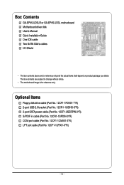
...-1FD001-7*R) 2-port USB 2.0 bracket (Part No. 12CR1-1UB030-5*R) 2-port SATA power cable (Part No. 12CF1-2SERPW-0*R) S/PDIF in cable (Part No. 12CR1-1SPDIN-0*R) COM port cable (Part No. 12CF1-1CM001-3*R) LPT port cable (Part No. 12CF1-1LP001-0*R) - 6 - Box Contents GA-EP45-UD3LR or GA-EP45-UD3L motherboard Motherboard driver disk User's Manual Quick Installation Guide One...
...-1FD001-7*R) 2-port USB 2.0 bracket (Part No. 12CR1-1UB030-5*R) 2-port SATA power cable (Part No. 12CF1-2SERPW-0*R) S/PDIF in cable (Part No. 12CR1-1SPDIN-0*R) COM port cable (Part No. 12CF1-1CM001-3*R) LPT port cable (Part No. 12CF1-1LP001-0*R) - 6 - Box Contents GA-EP45-UD3LR or GA-EP45-UD3L motherboard Motherboard driver disk User's Manual Quick Installation Guide One...
Manual
Page 9
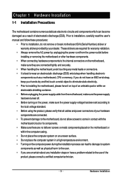
... or metal components placed on the motherboard or within an electrostatic shielding container. • Before unplugging the power supply cable from the power outlet before installing or removing the motherboard or other hardware components. • When connecting hardware components to ...on an uneven surface. • Do not place the computer system in a high-temperature environment. • Turning on the computer power during the installation process can become damaged as a motherboard, CPU or memory. Chapter 1 Hardware Installation 1-1 Installation Precautions The motherboard ...
... or metal components placed on the motherboard or within an electrostatic shielding container. • Before unplugging the power supply cable from the power outlet before installing or removing the motherboard or other hardware components. • When connecting hardware components to ...on an uneven surface. • Do not place the computer system in a high-temperature environment. • Turning on the computer power during the installation process can become damaged as a motherboard, CPU or memory. Chapter 1 Hardware Installation 1-1 Installation Precautions The motherboard ...
Manual
Page 11
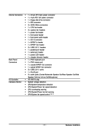
...; 1 x IDE connector 6 x SATA 3Gb/s connectors 1 x CPU fan header 2 x system fan headers 1 x power fan header 1 x front panel header 1 x front panel audio header 1 x CD In connector 1 x S/PDIF In...header 1 x S/PDIF Out header 2 x USB 2.0/1.1 headers 1 x parallel port header 1 x serial port header 1 x power LED header 1 x chassis intrusion header Back Panel 1 x PS/2 keyboard port Connectors 1 x PS/2 mouse port 1 x coaxial S/...
...; 1 x IDE connector 6 x SATA 3Gb/s connectors 1 x CPU fan header 2 x system fan headers 1 x power fan header 1 x front panel header 1 x front panel audio header 1 x CD In connector 1 x S/PDIF In...header 1 x S/PDIF Out header 2 x USB 2.0/1.1 headers 1 x parallel port header 1 x serial port header 1 x power LED header 1 x chassis intrusion header Back Panel 1 x PS/2 keyboard port Connectors 1 x PS/2 mouse port 1 x coaxial S/...
Manual
Page 13
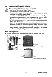
Hardware Installation It is not installed, otherwise overheating and damage of the CPU. mended that the motherboard supports the CPU. (Go to GIGABYTE's website for the peripherals. If you wish to set beyond the standard specifications, please do so according to your hardware specifications including the ...Alignment Key LGA 775 CPU Alignment Key Pin One Corner of the CPU. • Do not turn off the computer and unplug the power cord from the power outlet before you begin to install the CPU: • Make sure that the system bus frequency be inserted if oriented incorrectly. (...
Hardware Installation It is not installed, otherwise overheating and damage of the CPU. mended that the motherboard supports the CPU. (Go to GIGABYTE's website for the peripherals. If you wish to set beyond the standard specifications, please do so according to your hardware specifications including the ...Alignment Key LGA 775 CPU Alignment Key Pin One Corner of the CPU. • Do not turn off the computer and unplug the power cord from the power outlet before you begin to install the CPU: • Make sure that the system bus frequency be inserted if oriented incorrectly. (...

Manual
Page 14
... from the CPU socket. (DO NOT touch socket contacts.) Step 3: Remove the protective socket cover from the power outlet to prevent damage to turn off the computer and unplug the power cord from the load plate. (To protect the CPU socket, always replace the protective socket cover when the ...insert the CPU into position. CPU Socket Lever Step 1: Completely raise the CPU socket lever. Before installing the CPU, make sure to the CPU. GA-EP45-UD3LR/UD3L Motherboard - 14 - Align the CPU pin one marking (triangle) with the pin one corner of the CPU socket (or you may align the ...
... from the CPU socket. (DO NOT touch socket contacts.) Step 3: Remove the protective socket cover from the power outlet to prevent damage to turn off the computer and unplug the power cord from the load plate. (To protect the CPU socket, always replace the protective socket cover when the ...insert the CPU into position. CPU Socket Lever Step 1: Completely raise the CPU socket lever. Before installing the CPU, make sure to the CPU. GA-EP45-UD3LR/UD3L Motherboard - 14 - Align the CPU pin one marking (triangle) with the pin one corner of the CPU socket (or you may align the ...
Manual
Page 15
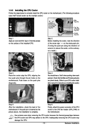
....) Step 1: Apply an even and thin layer of thermal grease on the surface of the motherboard. Push down each push pin. Step 6: Finally, attach the power connector of the CPU cooler to your CPU cooler installation manual for instructions on installing the cooler.) Step 5: After the installation, check the back of...
....) Step 1: Apply an even and thin layer of thermal grease on the surface of the motherboard. Push down each push pin. Step 6: Finally, attach the power connector of the CPU cooler to your CPU cooler installation manual for instructions on installing the cooler.) Step 5: After the installation, check the back of...
Manual
Page 16
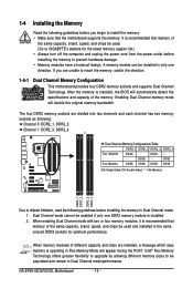
A memory module can be enabled if only one direction. DS/SS - - GA-EP45-UD3LR/UD3L Motherboard - 16 - If you begin to prevent hardware damage. • Memory modules have a foolproof design. The four DDR2 memory sockets are unable to insert the ... from the power outlet before installing the memory to install the memory: • Make sure that memory of the same capacity, brand, speed, and chips be used . (Go to GIGABYTE's website for optimum performance. When enabling Dual Channel mode with two or four memory modules, it is recommended that the motherboard supports...
A memory module can be enabled if only one direction. DS/SS - - GA-EP45-UD3LR/UD3L Motherboard - 16 - If you begin to prevent hardware damage. • Memory modules have a foolproof design. The four DDR2 memory sockets are unable to insert the ... from the power outlet before installing the memory to install the memory: • Make sure that memory of the same capacity, brand, speed, and chips be used . (Go to GIGABYTE's website for optimum performance. When enabling Dual Channel mode with two or four memory modules, it is recommended that the motherboard supports...
Manual
Page 17
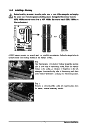
... at both ends of the memory socket. 1-4-2 Installing a Memory Before installing a memory module , make sure to turn off the computer and unplug the power cord from the power outlet to prevent damage to correctly install your fingers on the top edge of the memory, push down on the memory and insert it...
... at both ends of the memory socket. 1-4-2 Installing a Memory Before installing a memory module , make sure to turn off the computer and unplug the power cord from the power outlet to prevent damage to correctly install your fingers on the top edge of the memory, push down on the memory and insert it...

Manual
Page 18
...damage. Align the card with the expansion card in your expansion card. • Always turn off the computer and unplug the power cord from the power outlet before you begin to the chassis back panel with your operating system. If necessary, go to BIOS Setup to release the... Express x16 slot to make any required BIOS changes for your expansion card in the slot. 3. Remove the metal slot cover from the slot. GA-EP45-UD3LR/UD3L Motherboard - 18 - Secure the card's metal bracket to install an expansion card: • Make sure the motherboard supports the expansion card. 1-5...
...damage. Align the card with the expansion card in your expansion card. • Always turn off the computer and unplug the power cord from the power outlet before you begin to the chassis back panel with your operating system. If necessary, go to BIOS Setup to release the... Express x16 slot to make any required BIOS changes for your expansion card in the slot. 3. Remove the metal slot cover from the slot. GA-EP45-UD3LR/UD3L Motherboard - 18 - Secure the card's metal bracket to install an expansion card: • Make sure the motherboard supports the expansion card. 1-5...

Manual
Page 21
... 17) COMA 18) CI 19) CLR_CMOS 20) BAT 21) PHASE LED Read the following guidelines before turning on the motherboard. - 21 - Unplug the power cord from the power outlet to prevent damage to the devices. • After installing the device and before connecting external devices: • First make sure the device cable...
... 17) COMA 18) CI 19) CLR_CMOS 20) BAT 21) PHASE LED Read the following guidelines before turning on the motherboard. - 21 - Unplug the power cord from the power outlet to prevent damage to the devices. • After installing the device and before connecting external devices: • First make sure the device cable...
Manual
Page 22
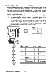
... 2x12-pinATX) GND (Only for 2x12-pin ATX) GA-EP45-UD3LR/UD3L Motherboard - 22 - 1/2) ATX_12V/ATX (2x2 12V Power Connector and 2x12 Main Power Connector) With the use of the power connector, the power supply can supply enough stable power to the CPU. The power connector possesses a foolproof design. Connect the power supply cable to an unstable or unbootable system...
... 2x12-pinATX) GND (Only for 2x12-pin ATX) GA-EP45-UD3LR/UD3L Motherboard - 22 - 1/2) ATX_12V/ATX (2x2 12V Power Connector and 2x12 Main Power Connector) With the use of the power connector, the power supply can supply enough stable power to the CPU. The power connector possesses a foolproof design. Connect the power supply cable to an unstable or unbootable system...

Manual
Page 23
... Installation 3/4/5) CPU_FAN/SYS_FAN1/SYS_FAN2/PWR_FAN (Fan Headers) The motherboard has a 4-pin CPU fan header (CPU_FAN), a 3-pin (SYS_FAN1) and a 4-pin (SYS_FAN2) system fan headers, and a 3-pin power fan header (PWR_FAN). For optimum heat dissipation, it in damage to locate pin 1 of a CPU fan with fan speed control design. Before connecting a floppy disk...
... Installation 3/4/5) CPU_FAN/SYS_FAN1/SYS_FAN2/PWR_FAN (Fan Headers) The motherboard has a 4-pin CPU fan header (CPU_FAN), a 3-pin (SYS_FAN1) and a 4-pin (SYS_FAN2) system fan headers, and a 3-pin power fan header (PWR_FAN). For optimum heat dissipation, it in damage to locate pin 1 of a CPU fan with fan speed control design. Before connecting a floppy disk...
Manual
Page 25
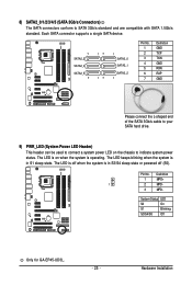
...7 Definition GND TXP TXN GND RXN RXP GND Please connect the L-shaped end of the SATA 3Gb/s cable to your SATA hard drive. 9) PWR_LED (System Power LED Header) This header can be used to SATA 3Gb/s standard and are compatible with SATA 1.5Gb/s standard. The LED is off (S5). 8) SATA2_0/1/2/3/4/5... (SATA 3Gb/s Connectors) The SATA connectors conform to connect a system power LED on when the system is in S1 sleep state. System Status LED S0 On S1 Blinking S3/S4/S5 Off Only for GA-EP45-UD3L. - 25 - Definition 1 MPD+ 1 2 MPD- 3 MPD-
...7 Definition GND TXP TXN GND RXN RXP GND Please connect the L-shaped end of the SATA 3Gb/s cable to your SATA hard drive. 9) PWR_LED (System Power LED Header) This header can be used to SATA 3Gb/s standard and are compatible with SATA 1.5Gb/s standard. The LED is off (S5). 8) SATA2_0/1/2/3/4/5... (SATA 3Gb/s Connectors) The SATA connectors conform to connect a system power LED on when the system is in S1 sleep state. System Status LED S0 On S1 Blinking S3/S4/S5 Off Only for GA-EP45-UD3L. - 25 - Definition 1 MPD+ 1 2 MPD- 3 MPD-
Manual
Page 26
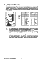
... No. Definition 1 1 2 2 MIC2_L GND 1 MIC 2 GND 3 MIC2_R 3 MIC Power 9 10 4 -ACZ_DET 4 NC 5 LINE2_R 5 Line Out (R) 6 GND 6 NC 7 FAUDIO_JD 7 NC 8 No Pin 8 No Pin 9 LINE2_L 9 Line Out (L) 10 GND 10 NC • The front panel audio header supports HD audio by default. GA-EP45-UD3LR/UD3L Motherboard - 26 - Definition Pin No. Make sure the wire...
... No. Definition 1 1 2 2 MIC2_L GND 1 MIC 2 GND 3 MIC2_R 3 MIC Power 9 10 4 -ACZ_DET 4 NC 5 LINE2_R 5 Line Out (R) 6 GND 6 NC 7 FAUDIO_JD 7 NC 8 No Pin 8 No Pin 9 LINE2_L 9 Line Out (L) 10 GND 10 NC • The front panel audio header supports HD audio by default. GA-EP45-UD3LR/UD3L Motherboard - 26 - Definition Pin No. Make sure the wire...

Manual
Page 27
.... Hardware Installation The LED is off when the system is reading or writing data. • RES (Reset Switch, Green): Connects to the power switch on when the system is detected, the BIOS may differ by issuing a beep code. If a problem is operating. The S0 On...on the chassis front panel. A front panel module mainly consists of power switch, reset switch, power LED, hard drive activity LED, speaker and etc. When connecting your system using the power switch (refer to Chapter 2, "BIOS Setup," "Power Management Setup," for information about beep codes. • HD (Hard...
.... Hardware Installation The LED is off when the system is reading or writing data. • RES (Reset Switch, Green): Connects to the power switch on when the system is detected, the BIOS may differ by issuing a beep code. If a problem is operating. The S0 On...on the chassis front panel. A front panel module mainly consists of power switch, reset switch, power LED, hard drive activity LED, speaker and etc. When connecting your system using the power switch (refer to Chapter 2, "BIOS Setup," "Power Management Setup," for information about beep codes. • HD (Hard...

Manual
Page 28
Definition 1 Power 2 SPDIFI 3 GND GA-EP45-UD3LR/UD3L Motherboard - 28 - 12) CD_IN (CD In Connector) You may connect the audio cable that came with your optical drive to an audio device that supports digital audio out via an optional S/PDIF in cable. Pin No. For purchasing the optional S/PDIF in and can connect to the header. Definition 1 CD-L 2 GND 3 GND 4 CD-R 1 13) SPDIF_I (S/PDIF In Heade) This header supports digital S/PDIF in cable, please contact the local dealer. 1 Pin No.
Definition 1 Power 2 SPDIFI 3 GND GA-EP45-UD3LR/UD3L Motherboard - 28 - 12) CD_IN (CD In Connector) You may connect the audio cable that came with your optical drive to an audio device that supports digital audio out via an optional S/PDIF in cable. Pin No. For purchasing the optional S/PDIF in and can connect to the header. Definition 1 CD-L 2 GND 3 GND 4 CD-R 1 13) SPDIF_I (S/PDIF In Heade) This header supports digital S/PDIF in cable, please contact the local dealer. 1 Pin No.

Manual
Page 29
... if you wish to connect an HDMI display to the graphics card and have digital audio output from the power outlet to prevent damage to turn off your computer and unplug the power cord from the HDMI display at the same time. Each USB header can provide two USB ports via an... optional USB bracket. For purchasing the optional USB bracket, please contact the local dealer. 9 1 10 2 Pin No. 1 2 3 4 5 6 7 8 9 10 Definition Power (5V) Power (5V) USB DXUSB DYUSB DX+ USB DY+ GND GND No Pin NC • Do not plug the IEEE 1394 bracket (2x5-pin) cable into the...
... if you wish to connect an HDMI display to the graphics card and have digital audio output from the power outlet to prevent damage to turn off your computer and unplug the power cord from the HDMI display at the same time. Each USB header can provide two USB ports via an... optional USB bracket. For purchasing the optional USB bracket, please contact the local dealer. 9 1 10 2 Pin No. 1 2 3 4 5 6 7 8 9 10 Definition Power (5V) Power (5V) USB DXUSB DYUSB DX+ USB DY+ GND GND No Pin NC • Do not plug the IEEE 1394 bracket (2x5-pin) cable into the...
Manual
Page 31
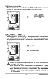
... been removed. Pin No. Open: Normal Short: Clear CMOS Values • Always turn off your computer, be sure to remove the jumper cap from the power outlet before clearing the CMOS values. • After clearing the CMOS values and before turning on the two pins to temporarily short the two pins... configurations). - 31 - This function requires a chassis with chassis intrusion detection design. To clear the CMOS values, place a jumper cap on your computer and unplug the power cord from the jumper.
... been removed. Pin No. Open: Normal Short: Clear CMOS Values • Always turn off your computer, be sure to remove the jumper cap from the power outlet before clearing the CMOS values. • After clearing the CMOS values and before turning on the two pins to temporarily short the two pins... configurations). - 31 - This function requires a chassis with chassis intrusion detection design. To clear the CMOS values, place a jumper cap on your computer and unplug the power cord from the jumper.
Manual
Page 32
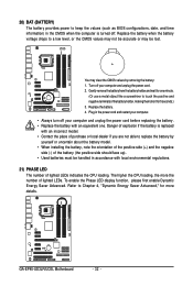
... keep the values (such as BIOS configurations, date, and time information) in the power cord and restart your computer. • Always turn off your computer and unplug the power cord. 2. Refer to Chapter 4, "Dynamic Energy Saver Advanced," for one . Replace the battery when the ... LEDs. Danger of explosion if the battery is turned off your computer and unplug the power cord before replacing the battery. • Replace the battery with local environmental regulations. 21) PHASE LED The number of lighted LEDs indicates the CPU loading. GA-EP45-UD3LR/UD3L Motherboard - 32 -
... keep the values (such as BIOS configurations, date, and time information) in the power cord and restart your computer. • Always turn off your computer and unplug the power cord. 2. Refer to Chapter 4, "Dynamic Energy Saver Advanced," for one . Replace the battery when the ... LEDs. Danger of explosion if the battery is turned off your computer and unplug the power cord before replacing the battery. • Replace the battery with local environmental regulations. 21) PHASE LED The number of lighted LEDs indicates the CPU loading. GA-EP45-UD3LR/UD3L Motherboard - 32 -


