Manual
Page 4
...GA-8VM800M-775 Motherboard Layout 6 Block Diagram ...7 Chapter 1 Hardware Installation 9 1-1 Considerations Prior to Installation 9 1-2 Feature Summary 10 1-3 Installation of the CPU and Heatsink 12 1-3-1 Installation of the CPU 12 1-3-2 Installation of the Heatsink 13 1-4 Installation of Memory 14 1-5 Installation of Expansion Cards 15 1-6 I/O Back Panel Introduction 16 1-7 Connectors Introduction 17 Chapter 2 BIOS... Setup 29 The Main Menu (For example: BIOS Ver. : E12 30 2-1 Standard CMOS Features 32 2-2 Advanced BIOS Features 34 2-3 ...
...GA-8VM800M-775 Motherboard Layout 6 Block Diagram ...7 Chapter 1 Hardware Installation 9 1-1 Considerations Prior to Installation 9 1-2 Feature Summary 10 1-3 Installation of the CPU and Heatsink 12 1-3-1 Installation of the CPU 12 1-3-2 Installation of the Heatsink 13 1-4 Installation of Memory 14 1-5 Installation of Expansion Cards 15 1-6 I/O Back Panel Introduction 16 1-7 Connectors Introduction 17 Chapter 2 BIOS... Setup 29 The Main Menu (For example: BIOS Ver. : E12 30 2-1 Standard CMOS Features 32 2-2 Advanced BIOS Features 34 2-3 ...

Manual
Page 5
Chapter 3 Drivers Installation 49 3-1 Install Chipset Drivers 49 3-2 SoftwareApplication 50 3-3 Software Information 50 3-4 Hardware Information 51 3-5 Contact Us ...51 Chapter 4 Appendix 53 4-1 Unique Software Utilities 53 4-1-1 EasyTune 5 Introduction 54 4-1-2 Xpress Recovery2 Introduction 55 4-1-3 Flash BIOS Method Introduction 57 4-1-4 Serial ATA BIOS Setting Utility Introduction 66 4-1-5 2 / 4 / 6 Channel Audio Function Introduction 73 4-2 Troubleshooting 79 - 5 -
Chapter 3 Drivers Installation 49 3-1 Install Chipset Drivers 49 3-2 SoftwareApplication 50 3-3 Software Information 50 3-4 Hardware Information 51 3-5 Contact Us ...51 Chapter 4 Appendix 53 4-1 Unique Software Utilities 53 4-1-1 EasyTune 5 Introduction 54 4-1-2 Xpress Recovery2 Introduction 55 4-1-3 Flash BIOS Method Introduction 57 4-1-4 Serial ATA BIOS Setting Utility Introduction 66 4-1-5 2 / 4 / 6 Channel Audio Function Introduction 73 4-2 Troubleshooting 79 - 5 -
Manual
Page 11
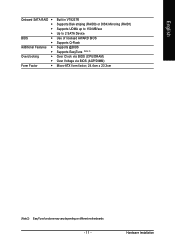
Hardware Installation English Onboard SATA RAID Š Š Š Š BIOS Š Š Additional Features Š Š Overclocking Š Š Form Factor Š Built in VT8237R Supports Disk striping (RAID0) or DISK Mirroring (RAID1) Supports UDMA up to 150 MB/sec Up to 2 SATA Device Use of licensed AWARD BIOS Supports Q-Flash Supports @BIOS Supports EasyTune (Note 2) Over Clock via BIOS (CPU/DRAM) Over Voltage via BIOS (AGP/DIMM) Micro-ATX form factor; 24.4cm x 23.3cm (Note 2) EasyTune functions may vary depending on different motherboards. - 11 -
Hardware Installation English Onboard SATA RAID Š Š Š Š BIOS Š Š Additional Features Š Š Overclocking Š Š Form Factor Š Built in VT8237R Supports Disk striping (RAID0) or DISK Mirroring (RAID1) Supports UDMA up to 150 MB/sec Up to 2 SATA Device Use of licensed AWARD BIOS Supports Q-Flash Supports @BIOS Supports EasyTune (Note 2) Over Clock via BIOS (CPU/DRAM) Over Voltage via BIOS (AGP/DIMM) Micro-ATX form factor; 24.4cm x 23.3cm (Note 2) EasyTune functions may vary depending on different motherboards. - 11 -
Manual
Page 12
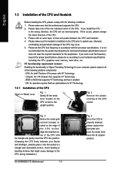
...An operation system that the motherboard supports the CPU. 2. Fig. 2 Remove the plastic covering on the CPU prior to the CPU during installation.) GA-8VM800M-775 Motherboard - 12 - Please add an even layer of the CPU Metal Lever Fig. 1 Gently lift the metal lever located on the edge ... memory, hard drive, etc. It is installed on the CPU socket. If you install the CPU in a straight and downwards motion. BIOS: A BIOS that supports HT Technology - Please make sure the heatsink is not recommended that might cause damage to system use, otherwise overheating and permanent ...
...An operation system that the motherboard supports the CPU. 2. Fig. 2 Remove the plastic covering on the CPU prior to the CPU during installation.) GA-8VM800M-775 Motherboard - 12 - Please add an even layer of the CPU Metal Lever Fig. 1 Gently lift the metal lever located on the edge ... memory, hard drive, etc. It is installed on the CPU socket. If you install the CPU in a straight and downwards motion. BIOS: A BIOS that supports HT Technology - Please make sure the heatsink is not recommended that might cause damage to system use, otherwise overheating and permanent ...
Manual
Page 14
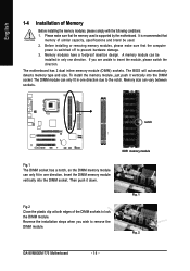
...A memory module can only fit in only one direction. The motherboard has 2 dual inline memory module (DIMM) sockets. Fig. 1 Fig. 2 GA-8VM800M-775 Motherboard - 14 - English 1-4 Installation of the DIMM sockets to lock the DIMM module. DDR memory module Fig.2 Close the plastic clip at both ...memory module can be used is switched off to the notch. Please make sure that the computer power is supported by the motherboard. The BIOS will automatically detects memory type and size. The DIMM module can vary between sockets. Memory size can only fit in one direction. Then ...
...A memory module can only fit in only one direction. The motherboard has 2 dual inline memory module (DIMM) sockets. Fig. 1 Fig. 2 GA-8VM800M-775 Motherboard - 14 - English 1-4 Installation of the DIMM sockets to lock the DIMM module. DDR memory module Fig.2 Close the plastic clip at both ...memory module can be used is switched off to the notch. Please make sure that the computer power is supported by the motherboard. The BIOS will automatically detects memory type and size. The DIMM module can vary between sockets. Memory size can only fit in one direction. Then ...

Manual
Page 15
Replace the screw to install/uninstall the VGA card. Install related driver from BIOS. 8. Hardware Installation Remove your computer's chassis cover. 7. Replace your computer's chassis cover, screws and slot bracket from the computer. 3. Installing a AGP expansion card: Please.... 4. Power on the slot. Please align the VGA card to the onboard AGP slot and press firmly down on the computer, if necessary, setup BIOS utility of expansion card from the operating system. Make sure your expansion card by the small white-drawable bar. - 15 - Press the expansion card ...
Replace the screw to install/uninstall the VGA card. Install related driver from BIOS. 8. Hardware Installation Remove your computer's chassis cover. 7. Replace your computer's chassis cover, screws and slot bracket from the computer. 3. Installing a AGP expansion card: Please.... 4. Power on the slot. Please align the VGA card to the onboard AGP slot and press firmly down on the computer, if necessary, setup BIOS utility of expansion card from the operating system. Make sure your expansion card by the small white-drawable bar. - 15 - Press the expansion card ...
Manual
Page 20
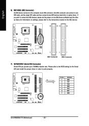
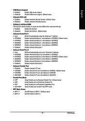
English 6) IDE1/IDE2 (IDE Connector) An IDE device connects to work properly. Pin No. Please refer to the BIOS setting for information on settings, please refer to the instructions located on one IDE cable, and the single IDE cable can then connect to 150MB/s ... the Serial ATA and install the proper driver in order to the computer via an IDE connector. Definition 1 GND 1 7 2 TXP 3 TXN 4 GND 5 RXN 6 RXP 7 GND GA-8VM800M-775 Motherboard - 20 - One IDE connector can provide up to two IDE devices (hard drive or optical drive).
English 6) IDE1/IDE2 (IDE Connector) An IDE device connects to work properly. Pin No. Please refer to the BIOS setting for information on settings, please refer to the instructions located on one IDE cable, and the single IDE cable can then connect to 150MB/s ... the Serial ATA and install the proper driver in order to the computer via an IDE connector. Definition 1 GND 1 7 2 TXP 3 TXN 4 GND 5 RXN 6 RXP 7 GND GA-8VM800M-775 Motherboard - 20 - One IDE connector can provide up to two IDE devices (hard drive or optical drive).
Manual
Page 26
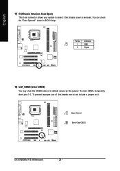
To prevent improper use of this jumper. English 17) CI (Chassis Intrusion, Case Open) This 2-pin connector allows your system to its default values by this header, we do not include a jumper on it. 1 Open: Normal 1 Short: Clear CMOS GA-8VM800M-775 Motherboard - 26 - You can check the "Case Opened" status in BIOS Setup. Definition 1 1 GND 2 Signal 18) CLR_CMOS (Clear CMOS) You may clear the CMOS data to detect if the chassis cover is removed. To clear CMOS, temporarily short pins 1-2. Pin No.
To prevent improper use of this jumper. English 17) CI (Chassis Intrusion, Case Open) This 2-pin connector allows your system to its default values by this header, we do not include a jumper on it. 1 Open: Normal 1 Short: Clear CMOS GA-8VM800M-775 Motherboard - 26 - You can check the "Case Opened" status in BIOS Setup. Definition 1 1 GND 2 Signal 18) CLR_CMOS (Clear CMOS) You may clear the CMOS data to detect if the chassis cover is removed. To clear CMOS, temporarily short pins 1-2. Pin No.

Manual
Page 29
... Save all the CMOS changes, only for the highlighted item. BIOS Setup You can be reset to a new BIOS, either GIGABYTE's Q-Flash or @BIOS utility can enter the BIOS setup screen by pressing "Ctrl + F1". To exit the Help Window press . - 29 - English Chapter 2 BIOS Setup BIOS (Basic Input and Output System) includes a CMOS SETUP utility which...
... Save all the CMOS changes, only for the highlighted item. BIOS Setup You can be reset to a new BIOS, either GIGABYTE's Q-Flash or @BIOS utility can enter the BIOS setup screen by pressing "Ctrl + F1". To exit the Help Window press . - 29 - English Chapter 2 BIOS Setup BIOS (Basic Input and Output System) includes a CMOS SETUP utility which...
Manual
Page 30
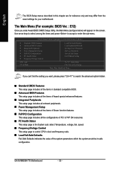
...hidden. „ Standard CMOS Features This setup page includes all the items in standard compatible BIOS. „ Advanced BIOS Features This setup page includes all the items of Award special enhanced features. „ ...BIOS Features ` Integrated Peripherals ` Power Management Setup ` PnP/PCI Configurations ` PC Health Status ` Frequency/Voltage Control ESC: Quit F8: Q-Flash Load Fail-Safe Defaults Load Optimized Defaults Set Supervisor Password Set User Password Save & Exit Setup Exit Without Saving KLJI: Select Item F10: Save & Exit Setup Time, Date, Hard Disk Type... GA-8VM800M-775...
...hidden. „ Standard CMOS Features This setup page includes all the items in standard compatible BIOS. „ Advanced BIOS Features This setup page includes all the items of Award special enhanced features. „ ...BIOS Features ` Integrated Peripherals ` Power Management Setup ` PnP/PCI Configurations ` PC Health Status ` Frequency/Voltage Control ESC: Quit F8: Q-Flash Load Fail-Safe Defaults Load Optimized Defaults Set Supervisor Password Set User Password Save & Exit Setup Exit Without Saving KLJI: Select Item F10: Save & Exit Setup Time, Date, Hard Disk Type... GA-8VM800M-775...

Manual
Page 31
English „ Load Optimized Defaults Optimized Defaults indicates the value of the system parameters which the system would be in best performance configuration. „ Set Supervisor Password Change, set , or disable password. BIOS Setup It allows you to limit access to the system. „ Save & Exit Setup Save CMOS value settings to Setup. „ Set User Password Change, set , or disable password. It allows you to limit access to the system and Setup, or just to CMOS and exit setup. „ Exit Without Saving Abandon all CMOS value changes and exit setup. - 31 -
English „ Load Optimized Defaults Optimized Defaults indicates the value of the system parameters which the system would be in best performance configuration. „ Set Supervisor Password Change, set , or disable password. BIOS Setup It allows you to limit access to the system. „ Save & Exit Setup Save CMOS value settings to Setup. „ Set User Password Change, set , or disable password. It allows you to limit access to the system and Setup, or just to CMOS and exit setup. „ Exit Without Saving Abandon all CMOS value changes and exit setup. - 31 -
Manual
Page 32
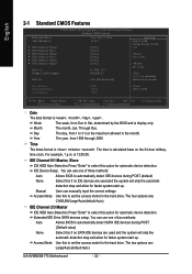
...devices during POST. (Default value) None Select this option for the hard drive. You can use one of two methods: Auto Allows BIOS to select this if no IDE devices are used and the system will skip the automatic detection step and allow for the hard drive.... devices during POST.(default) None Select this to Sat, determined by the BIOS and is , , , . You can manually input the correct settings Access Mode Use this if no SATA IDE devices are : Large/Auto(default:Auto) GA-8VM800M-775 Motherboard - 32 - Jan. Through Dec. Extended IDE Drive SATA devices setup...
...devices during POST. (Default value) None Select this option for the hard drive. You can use one of two methods: Auto Allows BIOS to select this if no IDE devices are used and the system will skip the automatic detection step and allow for the hard drive.... devices during POST.(default) None Select this to Sat, determined by the BIOS and is , , , . You can manually input the correct settings Access Mode Use this if no SATA IDE devices are : Large/Auto(default:Auto) GA-8VM800M-775 Motherboard - 32 - Jan. Through Dec. Extended IDE Drive SATA devices setup...

Manual
Page 33
...-type high-density drive; 1.2M byte capacity 720K, 3.5" (3.5 inch when 3 Mode is present during power up. All Errors Whenever the BIOS detects a non-fatal error the system will be labeled on The category determines whether the computer will determine the amount of base (or conventional...stop for all other errors. (Default value) All, But Diskette The system boot will not stop for a keyboard or disk error; Extended Memory The BIOS determines how much extended memory is Enabled). 3.5 inch double-sided drive; 720K byte capacity 1.44M, 3.5" 3.5 inch double-sided drive; 1.44M byte ...
...-type high-density drive; 1.2M byte capacity 720K, 3.5" (3.5 inch when 3 Mode is present during power up. All Errors Whenever the BIOS detects a non-fatal error the system will be labeled on The category determines whether the computer will determine the amount of base (or conventional...stop for all other errors. (Default value) All, But Diskette The system boot will not stop for a keyboard or disk error; Extended Memory The BIOS determines how much extended memory is Enabled). 3.5 inch double-sided drive; 720K byte capacity 1.44M, 3.5" 3.5 inch double-sided drive; 1.44M byte ...
Manual
Page 34
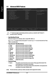
...Password Check System The system can not boot and can not access to Setup page will show up , or to exit this function. GA-8VM800M-775 Motherboard - 34 - First / Second / Third Boot Device Floppy Select your boot device priority by Floppy. Legacy LAN Select your boot ...device priority by Legacy LAN. ZIP Select your boot device priority by ZIP. English 2-2 Advanced BIOS Features CMOS Setup Utility-Copyright (C) 1984-2005 Award Software Advanced BIOS Features ` Hard Disk Boot Priority First Boot Device Second Boot Device Third Boot Device Password Check # ...
...Password Check System The system can not boot and can not access to Setup page will show up , or to exit this function. GA-8VM800M-775 Motherboard - 34 - First / Second / Third Boot Device Floppy Select your boot device priority by Floppy. Legacy LAN Select your boot ...device priority by Legacy LAN. ZIP Select your boot device priority by ZIP. English 2-2 Advanced BIOS Features CMOS Setup Utility-Copyright (C) 1984-2005 Award Software Advanced BIOS Features ` Hard Disk Boot Priority First Boot Device Second Boot Device Third Boot Device Password Check # ...
Manual
Page 35
Please note that this function. - 35 - BIOS Setup Limit CPUID Max. to 3 Enabled Disabled Limit CPUID Maximum value to 3 when use older OS like NT4. CPU Enhanced Halt (C1E) (Note) Enabled Disabled ...
Please note that this function. - 35 - BIOS Setup Limit CPUID Max. to 3 Enabled Disabled Limit CPUID Maximum value to 3 when use older OS like NT4. CPU Enhanced Halt (C1E) (Note) Enabled Disabled ...
Manual
Page 37
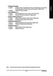
... (Default value) EPP Using Parallel port as Enhanced Parallel Port. Enabled Enable this function. (Default value) Onboard Serial Port 1 Auto 3F8/IRQ4 BIOS will automatically set up the Serial port 2 address. Enable onboard Serial port 1 and address is 3F8/IRQ4. (Default value) 2F8/IRQ3 Enable ... address is 3E8/IRQ4. 2E8/IRQ3 Disabled Enable onboard Serial port 2 and address is 2E8/IRQ3. Onboard Serial Port 2 Auto 3F8/IRQ4 BIOS will automatically setup the Serial port 1 address. Onboard Parallel Port Disabled Disable onboard LPT port. 378/IRQ7 278/IRQ5 Enable onboard LPT port...
... (Default value) EPP Using Parallel port as Enhanced Parallel Port. Enabled Enable this function. (Default value) Onboard Serial Port 1 Auto 3F8/IRQ4 BIOS will automatically set up the Serial port 2 address. Enable onboard Serial port 1 and address is 3F8/IRQ4. (Default value) 2F8/IRQ3 Enable ... address is 3E8/IRQ4. 2E8/IRQ3 Disabled Enable onboard Serial port 2 and address is 2E8/IRQ3. Onboard Serial Port 2 Auto 3F8/IRQ4 BIOS will automatically setup the Serial port 1 address. Onboard Parallel Port Disabled Disable onboard LPT port. 378/IRQ7 278/IRQ5 Enable onboard LPT port...

Manual
Page 39
... You can awake the system from any suspend state. If Resume by Alarm" item to enabled and key in Date/Time to power on system. BIOS Setup Disabled Disable this function. Disabled Disable this function. (Default value) Enabled Enable alarm function to POWER ON system. Enabled Enable PME as wake up...
... You can awake the system from any suspend state. If Resume by Alarm" item to enabled and key in Date/Time to power on system. BIOS Setup Disabled Disable this function. Disabled Disable this function. (Default value) Enabled Enable alarm function to POWER ON system. Enabled Enable PME as wake up...

Manual
Page 41
... VCORE DDR25V +3.3V +12V System Temperature CPU Temperature Current System FAN Speed Current CPU FAN Speed System Warning Temp. Monitor CPU temperature at 70oC / 158oF. BIOS Setup Case Opened If the case is closed, "Case Opened" will show "No". CPU Warning Temp. If the case have been opened, "Case Opened" will...
... VCORE DDR25V +3.3V +12V System Temperature CPU Temperature Current System FAN Speed Current CPU FAN Speed System Warning Temp. Monitor CPU temperature at 70oC / 158oF. BIOS Setup Case Opened If the case is closed, "Case Opened" will show "No". CPU Warning Temp. If the case have been opened, "Case Opened" will...

Manual
Page 43
... please wait 20secs. for Over_Clock. If you use DDR400 DRAM module, please set "DRAM Clock" to 255MHz. But it may occur. Auto +0.1V BIOS will automatically detect AGP voltage. (Default value) +0.1V Set AGP OverVoltage Control to +0.1V. +0.2V Set AGP OverVoltage Control to +0.2V. AGP OverVoltage...: Please note that by overclocking your system through the increase of the DDR voltage, damage to the memory may cause your system broken. BIOS Setup For power End-User use only! CPU Clock 200MHz ~255MHz Set CPU Clock from 200MHz to "166". If you use DDR333 DRAM...
... please wait 20secs. for Over_Clock. If you use DDR400 DRAM module, please set "DRAM Clock" to 255MHz. But it may occur. Auto +0.1V BIOS will automatically detect AGP voltage. (Default value) +0.1V Set AGP OverVoltage Control to +0.1V. +0.2V Set AGP OverVoltage Control to +0.2V. AGP OverVoltage...: Please note that by overclocking your system through the increase of the DDR voltage, damage to the memory may cause your system broken. BIOS Setup For power End-User use only! CPU Clock 200MHz ~255MHz Set CPU Clock from 200MHz to "166". If you use DDR333 DRAM...

Manual
Page 44
... F10: Save & Exit Setup Load Optimized Defaults Selecting this field loads the factory defaults for BIOS and Chipset Features which the system automatically detects. GA-8VM800M-775 Motherboard - 44 - English 2-8 Load Fail-Safe Defaults CMOS Setup Utility-Copyright (C) 1984-2005... Award Software ` Standard CMOS Features ` Advanced BIOS Features ` Integrated Peripherals ` Power Management Setup ` PnP/PCI Configurations ` ...
... F10: Save & Exit Setup Load Optimized Defaults Selecting this field loads the factory defaults for BIOS and Chipset Features which the system automatically detects. GA-8VM800M-775 Motherboard - 44 - English 2-8 Load Fail-Safe Defaults CMOS Setup Utility-Copyright (C) 1984-2005... Award Software ` Standard CMOS Features ` Advanced BIOS Features ` Integrated Peripherals ` Power Management Setup ` PnP/PCI Configurations ` ...


