Manual
Page 4
... CPU 12 1-3-2 Installation of the Heatsink 13 1-4 Installation of Memory 14 1-5 Installation of Expansion Cards 15 1-6 I/O Back Panel Introduction 16 1-7 Connectors Introduction 17 Chapter 2 BIOS Setup 29 The Main Menu (For example: BIOS Ver. : E12 30 2-1 Standard CMOS Features 32 2-2 Advanced BIOS Features 34 2-3 IntegratedPeripherals 36 2-4 Power Management Setup 38 2-5 PnP/PCI Configurations 40 2-6 PC Health Status 41 2-7 Frequency / Voltage Control 42 2-8 Load Fail-Safe Defaults 44 2-9 Load Optimized Defaults 44 2-10 Set Supervisor/User Password 45 2-11 Save & Exit Setup...
... CPU 12 1-3-2 Installation of the Heatsink 13 1-4 Installation of Memory 14 1-5 Installation of Expansion Cards 15 1-6 I/O Back Panel Introduction 16 1-7 Connectors Introduction 17 Chapter 2 BIOS Setup 29 The Main Menu (For example: BIOS Ver. : E12 30 2-1 Standard CMOS Features 32 2-2 Advanced BIOS Features 34 2-3 IntegratedPeripherals 36 2-4 Power Management Setup 38 2-5 PnP/PCI Configurations 40 2-6 PC Health Status 41 2-7 Frequency / Voltage Control 42 2-8 Load Fail-Safe Defaults 44 2-9 Load Optimized Defaults 44 2-10 Set Supervisor/User Password 45 2-11 Save & Exit Setup...
Manual
Page 10
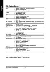
GA-8VM800M-775 Motherboard - 10 - MIC In Š Supports 2 / 4 / 6 channel audio Š SPDIF In / Out connection Š CD In / AUX In connection Š Supports Jack Sensing (Connector Sensing) function Š Winbond W83627 Š CPU / System fan speed detection Š System voltage detection Š CPU / System temperature detection Š CPU Smart Fan Control (Note 1) It is recommended to 2GB (Max.) Š 1 AGP slot 4X/8X (1.5V) device support Š 3 PCI slots Š 2 IDE connection (UDMA 33/ATA 66/ATA 100/ATA133), allows...
GA-8VM800M-775 Motherboard - 10 - MIC In Š Supports 2 / 4 / 6 channel audio Š SPDIF In / Out connection Š CD In / AUX In connection Š Supports Jack Sensing (Connector Sensing) function Š Winbond W83627 Š CPU / System fan speed detection Š System voltage detection Š CPU / System temperature detection Š CPU Smart Fan Control (Note 1) It is recommended to 2GB (Max.) Š 1 AGP slot 4X/8X (1.5V) device support Š 3 PCI slots Š 2 IDE connection (UDMA 33/ATA 66/ATA 100/ATA133), allows...
Manual
Page 14
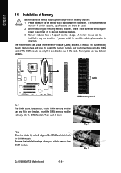
.... notch Fig.1 The DIMM socket has a notch, so the DIMM memory module can vary between sockets. It is switched off to lock the DIMM module. The motherboard has 2 dual inline memory module (DIMM) sockets. Memory size can only fit in only one direction. Fig. 1 Fig. 2 GA-8VM800M-775 Motherboard - 14 - Please make sure that the computer power is recommended that the memory used . 2. Then push it vertically...
.... notch Fig.1 The DIMM socket has a notch, so the DIMM memory module can vary between sockets. It is switched off to lock the DIMM module. The motherboard has 2 dual inline memory module (DIMM) sockets. Memory size can only fit in only one direction. Fig. 1 Fig. 2 GA-8VM800M-775 Motherboard - 14 - Please make sure that the computer power is recommended that the memory used . 2. Then push it vertically...
Manual
Page 20
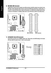
Pin No. English 6) IDE1/IDE2 (IDE Connector) An IDE device connects to work properly. Definition 1 GND 1 7 2 TXP 3 TXN 4 GND 5 RXN 6 RXP 7 GND GA-8VM800M-775 Motherboard - 20 - If you wish to connect two IDE devices, please set the jumper on the IDE device). 40 39 40 39 2 12 1 IDE1 Connector IDE2 Connector 7) SATA0/SATA1 (Serial ATA Connector) Serial ATA can then connect to 150MB/s transfer rate. Please refer to the BIOS setting for information on settings, please refer...
Pin No. English 6) IDE1/IDE2 (IDE Connector) An IDE device connects to work properly. Definition 1 GND 1 7 2 TXP 3 TXN 4 GND 5 RXN 6 RXP 7 GND GA-8VM800M-775 Motherboard - 20 - If you wish to connect two IDE devices, please set the jumper on the IDE device). 40 39 40 39 2 12 1 IDE1 Connector IDE2 Connector 7) SATA0/SATA1 (Serial ATA Connector) Serial ATA can then connect to 150MB/s transfer rate. Please refer to the BIOS setting for information on settings, please refer...

Manual
Page 21
... MSG(Message LED/Power/Sleep LED) NC Reset Switch IDE Hard Disk Active LED Pin 1: LED anode(+) Pin 2: LED cathode(-) Pin 1: Power Pin 2- Pin 3: NC Pin 4: Data(-) Open: Normal Close: Reset Hardware System Open: Normal Close: Power On/Off Pin 1: LED anode(+) Pin 2: LED cathode(-) NC - 21 - Hardware Installation of your chassis front panel to the F_PANEL connector according to the pin assignments below. English 8) F_PANEL (Front Panel Connector) Please connect the power LED, PC speaker, reset switch and power switch etc. Message LED/ Power/ Sleep LED Speaker Connector Power Switch MSG...
... MSG(Message LED/Power/Sleep LED) NC Reset Switch IDE Hard Disk Active LED Pin 1: LED anode(+) Pin 2: LED cathode(-) Pin 1: Power Pin 2- Pin 3: NC Pin 4: Data(-) Open: Normal Close: Reset Hardware System Open: Normal Close: Power On/Off Pin 1: LED anode(+) Pin 2: LED cathode(-) NC - 21 - Hardware Installation of your chassis front panel to the F_PANEL connector according to the pin assignments below. English 8) F_PANEL (Front Panel Connector) Please connect the power LED, PC speaker, reset switch and power switch etc. Message LED/ Power/ Sleep LED Speaker Connector Power Switch MSG...
Manual
Page 30
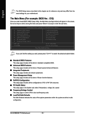
... ` Frequency/Voltage Control ESC: Quit F8: Q-Flash Load Fail-Safe Defaults Load Optimized Defaults Set Supervisor Password Set User Password Save & Exit Setup Exit Without Saving KLJI: Select Item F10: Save & Exit Setup Time, Date, Hard Disk Type... The Main Menu (For example: BIOS Ver. : E12) Once you want, please press "Ctrl+F1" to accept or enter the sub-menu. English The BIOS Setup menus described in safe configuration. GA-8VM800M-775 Motherboard - 30 - If you can't find the setting you enter Award BIOS CMOS Setup Utility, the Main Menu (as...
... ` Frequency/Voltage Control ESC: Quit F8: Q-Flash Load Fail-Safe Defaults Load Optimized Defaults Set Supervisor Password Set User Password Save & Exit Setup Exit Without Saving KLJI: Select Item F10: Save & Exit Setup Time, Date, Hard Disk Type... The Main Menu (For example: BIOS Ver. : E12) Once you want, please press "Ctrl+F1" to accept or enter the sub-menu. English The BIOS Setup menus described in safe configuration. GA-8VM800M-775 Motherboard - 30 - If you can't find the setting you enter Award BIOS CMOS Setup Utility, the Main Menu (as...
Manual
Page 32
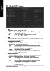
..., 1 p.m. Manual User can use one of three methods: Auto Allows BIOS to 2098 KLJI: Move Enter: Select F5: Previous Values +/-/PU/PD: Value F10: Save ESC: Exit F6: Fail-Safe Defaults F7: Optimized Defaults F1: General Help Date The date format is display only The month, Jan. IDE Channel 0/1 Master, Slave IDE HDD Auto-Detection Press "Enter" to set the access mode for automatic device detection. The four options are : Large/Auto(default:Auto) GA-8VM800M-775 Motherboard...
..., 1 p.m. Manual User can use one of three methods: Auto Allows BIOS to 2098 KLJI: Move Enter: Select F5: Previous Values +/-/PU/PD: Value F10: Save ESC: Exit F6: Fail-Safe Defaults F7: Optimized Defaults F1: General Help Date The date format is display only The month, Jan. IDE Channel 0/1 Master, Slave IDE HDD Auto-Detection Press "Enter" to set the access mode for automatic device detection. The four options are : Large/Auto(default:Auto) GA-8VM800M-775 Motherboard...
Manual
Page 38
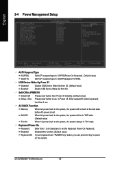
... always in "Off" state. (Default value) Full-On When AC-power back to S3/STR(Suspend To RAM). Disabled this function. (Default value) If your keyboard have "POWER Key" button, you can press the key to set the Keyboard Power On Password. Press power button 4 sec. Enter suspend if button is lost. USB Device Wake-Up From S3 Disabled Disable USB Device Wake-Up from S3. (Default value) Enabled Enable USB Device Wake-Up from 1 to 8 characters to power on the system. GA-8VM800M-775 Motherboard - 38 -
... always in "Off" state. (Default value) Full-On When AC-power back to S3/STR(Suspend To RAM). Disabled this function. (Default value) If your keyboard have "POWER Key" button, you can press the key to set the Keyboard Power On Password. Press power button 4 sec. Enter suspend if button is lost. USB Device Wake-Up From S3 Disabled Disable USB Device Wake-Up from S3. (Default value) Enabled Enable USB Device Wake-Up from 1 to 8 characters to power on the system. GA-8VM800M-775 Motherboard - 38 -

Manual
Page 42
... power end-user use only. Spread Spectrum Enabled Enable clock spread spectrum. (Default value) Disabled Disable this function. (Note) This item will show up when you install a processor which supports this function. English System/CPU FAN Fail Warning Disabled Fan warning function disable. (Default value) Enabled Fan warning function enable. CPU Clock Ratio (Note) This setup option will run at different speed depending on their requirements. (Default Value) 2-7 Frequency / Voltage Control CMOS Setup Utility-Copyright (C) 1984-2005 Award Software Frequency/Voltage Control...
... power end-user use only. Spread Spectrum Enabled Enable clock spread spectrum. (Default value) Disabled Disable this function. (Note) This item will show up when you install a processor which supports this function. English System/CPU FAN Fail Warning Disabled Fan warning function disable. (Default value) Enabled Fan warning function enable. CPU Clock Ratio (Note) This setup option will run at different speed depending on their requirements. (Default Value) 2-7 Frequency / Voltage Control CMOS Setup Utility-Copyright (C) 1984-2005 Award Software Frequency/Voltage Control...

Manual
Page 45
...2-10 Set Supervisor/User Password CMOS Setup Utility-Copyright (C) 1984-2005 Award Software ` Standard CMOS Features ` Advanced BIOS Features ` Integrated Peripherals ` Power Management Setup ` PnP/PCI ConfigurationEsnter Password: ` PC Health Status ` Frequency/Voltage Control Load Fail-Safe Defaults Load Optimized Defaults Set Supervisor Password Set User Password Save & Exit Setup Exit Without Saving ESC: Quit F8: Q-Flash KLJI: Select Item F10: Save & Exit Setup Change/Set/Disable Password When you select this function, the following message will appear at the center of the screen to...
...2-10 Set Supervisor/User Password CMOS Setup Utility-Copyright (C) 1984-2005 Award Software ` Standard CMOS Features ` Advanced BIOS Features ` Integrated Peripherals ` Power Management Setup ` PnP/PCI ConfigurationEsnter Password: ` PC Health Status ` Frequency/Voltage Control Load Fail-Safe Defaults Load Optimized Defaults Set Supervisor Password Set User Password Save & Exit Setup Exit Without Saving ESC: Quit F8: Q-Flash KLJI: Select Item F10: Save & Exit Setup Change/Set/Disable Password When you select this function, the following message will appear at the center of the screen to...

Manual
Page 53
... access and change system settings such as CPU, memory, graphics card, etc. Appendix C.O.M. (Corporate Online Management) A web-based system management tool that eliminates system boot-up the PC chassis and short-circuit the "Clear CMOS" pins or the battery on the original M.I.B., the new Memory Intelligent Booster 2 (M.I .T.) allows user to -date drivers and BIOS. (Do not use C.O.M. Designed to provide a more user-friendly and reliable platform for users. M.I.T. (Motherboard Intelligent Tweaker) Motherboard Intelligent...
... access and change system settings such as CPU, memory, graphics card, etc. Appendix C.O.M. (Corporate Online Management) A web-based system management tool that eliminates system boot-up the PC chassis and short-circuit the "Clear CMOS" pins or the battery on the original M.I.B., the new Memory Intelligent Booster 2 (M.I .T.) allows user to -date drivers and BIOS. (Do not use C.O.M. Designed to provide a more user-friendly and reliable platform for users. M.I.T. (Motherboard Intelligent Tweaker) Motherboard Intelligent...
Manual
Page 55
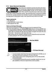
... installations of OS and all required drivers as well as software. - 55 - Intel 945 BIOS for the first time, it will appear in the future. 2. If you can simply press F9 during system power-on PATA and SATA IDE controllers. VESA-supported VGA cards How to use the Xpress Recovery2 Initial access by booting from the CD-ROM, you wish to startup XpressRecovery2..... Press any key...
... installations of OS and all required drivers as well as software. - 55 - Intel 945 BIOS for the first time, it will appear in the future. 2. If you can simply press F9 during system power-on PATA and SATA IDE controllers. VESA-supported VGA cards How to use the Xpress Recovery2 Initial access by booting from the CD-ROM, you wish to startup XpressRecovery2..... Press any key...

Manual
Page 58
... keyboard and then Y button to Floppy Enter : Run :Move ESC:Reset F10:Power Off Dual BIOS utility bar Q-FlashTM utility title bar Action bar Task menu for Q-Flash utility: Contains the names of four actions needed to enter BIOS menu. GA-8VM800M-775 Motherboard - 58 - Task menu for Dual BIOS utility Task menu for Q-FlashTM utility Dual BIOS Utility Boot From Main Bios Main ROM Type/Size SST 49LF003A Backup ROM Type/Size SST 49LF003A 512K 512K Wide Range Protection Disable Boot From Main Bios Auto Recovery Enable Halt On Error Disable Copy Main ROM Data to Backup Load Default...
... keyboard and then Y button to Floppy Enter : Run :Move ESC:Reset F10:Power Off Dual BIOS utility bar Q-FlashTM utility title bar Action bar Task menu for Q-Flash utility: Contains the names of four actions needed to enter BIOS menu. GA-8VM800M-775 Motherboard - 58 - Task menu for Dual BIOS utility Task menu for Q-FlashTM utility Dual BIOS Utility Boot From Main Bios Main ROM Type/Size SST 49LF003A Backup ROM Type/Size SST 49LF003A 512K 512K Wide Range Protection Disable Boot From Main Bios Auto Recovery Enable Halt On Error Disable Copy Main ROM Data to Backup Load Default...

Manual
Page 60
... Backup BIOS to update BIOS. Load Default Settings Save Settings to CMOS Q-Flash Utility Load Main BIOS from Floppy Load Backup BIOS from Floppy Save Main BIOS to Floppy Save Backup BIOS to Floppy Enter : Run :Move ESC:Reset F10:Power Off You can repeat Step 1 to 4 to enter SETUP / Dual BIOS / Q-Flash / F9 For Xpress Recovery 09/23/2003-i875P-6A79BG03C-00 GA-8VM800M-775 Motherboard - 60 - Intel i875P AGPset BIOS for 8KNXP Ultra Fba Check System Health OK , VCore = 1.5250 Main Processor : Intel Pentium(R) 4 1.6GHz (133x12) Memory...
... Backup BIOS to update BIOS. Load Default Settings Save Settings to CMOS Q-Flash Utility Load Main BIOS from Floppy Load Backup BIOS from Floppy Save Main BIOS to Floppy Save Backup BIOS to Floppy Enter : Run :Move ESC:Reset F10:Power Off You can repeat Step 1 to 4 to enter SETUP / Dual BIOS / Q-Flash / F9 For Xpress Recovery 09/23/2003-i875P-6A79BG03C-00 GA-8VM800M-775 Motherboard - 60 - Intel i875P AGPset BIOS for 8KNXP Ultra Fba Check System Health OK , VCore = 1.5250 Main Processor : Intel Pentium(R) 4 1.6GHz (133x12) Memory...

Manual
Page 61
... Power Management Setup Save to enter BIOS menu after BIOS has been upgraded. CMOS Setup Utility-Copyright (C) 1984-2004 Award Software Standard CMOS Features Select Language Advanced BIOS Features Load Fail-Safe Defaults Integrated Peripherals Load Optimized Defaults Power Management Setup Load Fail-Safe Defaults (YS/eNt )S?uYpervisor Password PnP/PCI Configurations Set User Password PC Health Status Save & Exit Setup MB Intelligent Tweaker(M.I.T.) Exit Without Saving ESC: Quit F8: Dual BIOS/Q-Flash F3: Change Language F10: Save & Exit Setup Time, Date, Hard Disk Type...
... Power Management Setup Save to enter BIOS menu after BIOS has been upgraded. CMOS Setup Utility-Copyright (C) 1984-2004 Award Software Standard CMOS Features Select Language Advanced BIOS Features Load Fail-Safe Defaults Integrated Peripherals Load Optimized Defaults Power Management Setup Load Fail-Safe Defaults (YS/eNt )S?uYpervisor Password PnP/PCI Configurations Set User Password PC Health Status Save & Exit Setup MB Intelligent Tweaker(M.I.T.) Exit Without Saving ESC: Quit F8: Dual BIOS/Q-Flash F3: Change Language F10: Save & Exit Setup Time, Date, Hard Disk Type...
Manual
Page 64
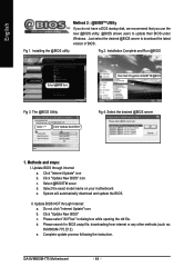
.../ GIGABYTE/@BIOS Fig 3. Click "Update New BIOS" c. Please select "All Files" in dialog box while opening the old file. d. e. Update BIOS through Internet: a. Complete update process following the instruction. GA-8VM800M-775 Motherboard - 64 - Select @BIOSTM sever d. Installing the @BIOS utility Fig 2. System will automatically download and update the BIOS. Do not click "Internet Update" icon b. Click "Update New BIOS" icon c. Just select the desired @BIOS server to update their BIOS under Windows. Please search for BIOS unzip file, downloading...
.../ GIGABYTE/@BIOS Fig 3. Click "Update New BIOS" c. Please select "All Files" in dialog box while opening the old file. d. e. Update BIOS through Internet: a. Complete update process following the instruction. GA-8VM800M-775 Motherboard - 64 - Select @BIOSTM sever d. Installing the @BIOS utility Fig 2. System will automatically download and update the BIOS. Do not click "Internet Update" icon b. Click "Update New BIOS" icon c. Just select the desired @BIOS server to update their BIOS under Windows. Please search for BIOS unzip file, downloading...

Manual
Page 67
... hard disks attached to VIA RAID controller F1 : View Array/disk Status , : Move to select Silicon Image). 5) Complete driver installation. 6) Complete RAID utility installation. VIA VT8237 Serial ATA RAID BIOS Setting Utility V2.31 Copyright (C) VIA Technologies, Inc. English Please follow the steps below to construct a complete RAID array: 1) Have ready your computer, wait until you see the RAID software prompting you to press Tab. IDE, SCSI, or SATA. 3) Enter the motherboard BIOS and locate RAID setup...
... hard disks attached to VIA RAID controller F1 : View Array/disk Status , : Move to select Silicon Image). 5) Complete driver installation. 6) Complete RAID utility installation. VIA VT8237 Serial ATA RAID BIOS Setting Utility V2.31 Copyright (C) VIA Technologies, Inc. English Please follow the steps below to construct a complete RAID array: 1) Have ready your computer, wait until you see the RAID software prompting you to press Tab. IDE, SCSI, or SATA. 3) Enter the motherboard BIOS and locate RAID setup...
Manual
Page 72
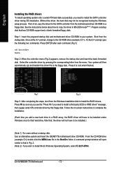
... controller driver by this driver file to install the SATA controller driver during the Windows setup process. Boot from the motherboard driver CD-ROM to install the RAID drivers. Press ENTER after each command (Fig.1): cd bootdrv menu Step 2: When the controller menu (Fig.2) appears, remove the startup disk and insert the blank formatted disk. At the D:\> prompt, type the following two commands. English Installing the RAID drivers To install operating system onto a serial ATA hard disk successfully, you need to install 64-bit Windows...
... controller driver by this driver file to install the SATA controller driver during the Windows setup process. Boot from the motherboard driver CD-ROM to install the RAID drivers. Press ENTER after each command (Fig.1): cd bootdrv menu Step 2: When the controller menu (Fig.2) appears, remove the startup disk and insert the blank formatted disk. At the D:\> prompt, type the following two commands. English Installing the RAID drivers To install operating system onto a serial ATA hard disk successfully, you need to install 64-bit Windows...

Manual
Page 73
Line Out STEP 2: After installing the audio driver, you use speakers with amplifier to get the best sound effect if the stereo output is applied. STEP 3: On the AC97 Audio Configuration menu, click the Speaker Configuration tab and select the 2-channel mode for stereo speaker output check box. - 73 - STEP 1: Connect the stereo speakers or earphone to select the function. Click the icon to "Line Out." English 4-1-5 2 / 4 / 6 Channel Audio Function Introduction 2 Channel Audio Setup We recommend that you 'll find a Sound Effect icon on the lower right hand taskbar. Appendix
Line Out STEP 2: After installing the audio driver, you use speakers with amplifier to get the best sound effect if the stereo output is applied. STEP 3: On the AC97 Audio Configuration menu, click the Speaker Configuration tab and select the 2-channel mode for stereo speaker output check box. - 73 - STEP 1: Connect the stereo speakers or earphone to select the function. Click the icon to "Line Out." English 4-1-5 2 / 4 / 6 Channel Audio Function Introduction 2 Channel Audio Setup We recommend that you 'll find a Sound Effect icon on the lower right hand taskbar. Appendix

Manual
Page 79
... version. Disconnect the power cord from case to case. Answer: Please make sure the speaker you can take off power. 2. Please refer to the battery holder. 5. gate A20 failure 7 beeps Processor exception interrupt error 8 beeps Display memory read/write failure 9 beeps ROM checksum error 10 beeps CMOS shutdown register read/write error 11 beeps Cache memory bad AWARD BIOS Beep Codes 1 short: System boots successfully 2 short: CMOS setting error 1 long 1 short: DRAM or M/B error 1 long 2 short: Monitor or display card error 1 long 3 short: Keyboard error 1 long 9 short: BIOS...
... version. Disconnect the power cord from case to case. Answer: Please make sure the speaker you can take off power. 2. Please refer to the battery holder. 5. gate A20 failure 7 beeps Processor exception interrupt error 8 beeps Display memory read/write failure 9 beeps ROM checksum error 10 beeps CMOS shutdown register read/write error 11 beeps Cache memory bad AWARD BIOS Beep Codes 1 short: System boots successfully 2 short: CMOS setting error 1 long 1 short: DRAM or M/B error 1 long 2 short: Monitor or display card error 1 long 3 short: Keyboard error 1 long 9 short: BIOS...


