Manual
Page 4
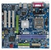
Table of Contents GA-8VM800M-775 Motherboard Layout 6 Block Diagram ...7 Chapter 1 Hardware Installation 9 1-1 Considerations Prior to Installation 9 1-2 Feature Summary 10 1-3 Installation of the CPU and Heatsink 12 1-3-1 Installation of the CPU 12 1-3-2 Installation of the Heatsink 13 1-4 Installation of Memory 14 1-5 Installation of Expansion Cards 15 1-6 I/O Back Panel Introduction 16 1-7 Connectors Introduction 17 Chapter 2 BIOS Setup...
Table of Contents GA-8VM800M-775 Motherboard Layout 6 Block Diagram ...7 Chapter 1 Hardware Installation 9 1-1 Considerations Prior to Installation 9 1-2 Feature Summary 10 1-3 Installation of the CPU and Heatsink 12 1-3-1 Installation of the CPU 12 1-3-2 Installation of the Heatsink 13 1-4 Installation of Memory 14 1-5 Installation of Expansion Cards 15 1-6 I/O Back Panel Introduction 16 1-7 Connectors Introduction 17 Chapter 2 BIOS Setup...

Manual
Page 9
...supply connector from the motherboard. It is switched off the computer and unplug its components. 5. Product determined to be an unofficial Gigabyte product. - 9 - Before using the product, please verify that the power supply is best to wear an electrostatic discharge (ESD...) cuff when handling electronic components (CPU, RAM). 4. These stickers are no leftover screws or metal components placed on the computer power during the installation process can become ...
...supply connector from the motherboard. It is switched off the computer and unplug its components. 5. Product determined to be an unofficial Gigabyte product. - 9 - Before using the product, please verify that the power supply is best to wear an electrostatic discharge (ESD...) cuff when handling electronic components (CPU, RAM). 4. These stickers are no leftover screws or metal components placed on the computer power during the installation process can become ...
Manual
Page 10
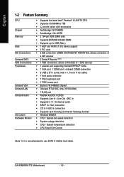
... Š Supports up to use SATA (1.5Gb/s) hard disks. GA-8VM800M-775 Motherboard - 10 - Line Out ; MIC In Š Supports 2 / 4 / 6 channel audio Š SPDIF In / Out connection Š CD In / AUX In connection Š Supports Jack Sensing (Connector Sensing) function Š Winbond W83627 Š CPU / System fan speed detection Š System voltage detection Š...
... Š Supports up to use SATA (1.5Gb/s) hard disks. GA-8VM800M-775 Motherboard - 10 - Line Out ; MIC In Š Supports 2 / 4 / 6 channel audio Š SPDIF In / Out connection Š CD In / AUX In connection Š Supports Jack Sensing (Connector Sensing) function Š Winbond W83627 Š CPU / System fan speed detection Š System voltage detection Š...
Manual
Page 11
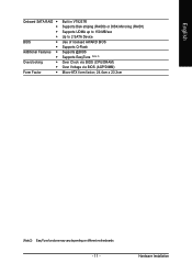
English Onboard SATA RAID Š Š Š Š BIOS Š Š Additional Features Š Š Overclocking Š Š Form Factor Š Built in VT8237R Supports Disk striping (RAID0) or DISK Mirroring (RAID1) Supports UDMA up to 150 MB/sec Up to 2 SATA Device Use of licensed AWARD BIOS Supports Q-Flash Supports @BIOS Supports EasyTune (Note 2) Over Clock via BIOS (CPU/DRAM) Over Voltage via BIOS (AGP/DIMM) Micro-ATX form factor; 24.4cm x 23.3cm (Note 2) EasyTune functions may vary depending on different motherboards. - 11 - Hardware Installation
English Onboard SATA RAID Š Š Š Š BIOS Š Š Additional Features Š Š Overclocking Š Š Form Factor Š Built in VT8237R Supports Disk striping (RAID0) or DISK Mirroring (RAID1) Supports UDMA up to 150 MB/sec Up to 2 SATA Device Use of licensed AWARD BIOS Supports Q-Flash Supports @BIOS Supports EasyTune (Note 2) Over Clock via BIOS (CPU/DRAM) Over Voltage via BIOS (AGP/DIMM) Micro-ATX form factor; 24.4cm x 23.3cm (Note 2) EasyTune functions may vary depending on different motherboards. - 11 - Hardware Installation
Manual
Page 12
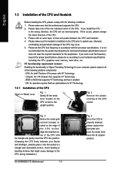
... supports HT Technology - Fig. 3 Notice the small gold colored triangle located on the CPU socket. Please make sure the heatsink is installed on the CPU socket to the CPU during installation.) GA-8VM800M-775 Motherboard - 12 - Please add an even layer of the CPU may occur. 5. It is properly inserted, please replace the load plate and push...
... supports HT Technology - Fig. 3 Notice the small gold colored triangle located on the CPU socket. Please make sure the heatsink is installed on the CPU socket to the CPU during installation.) GA-8VM800M-775 Motherboard - 12 - Please add an even layer of the CPU may occur. 5. It is properly inserted, please replace the load plate and push...
Manual
Page 13
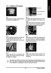
...push pin are joined closely. (for heat dissipation or using extreme care when removing the heatsink. - 13 - The heatsink may adhere to the CPU fan header located on the motherboard. English 1-3-2 Installation of the Heatsink Male Push Pin The top of Female Push Pin Female Push Pin Fig.1 ... thermal tape rather than heat sink paste be used for detailed installation instructions, please refer to the pin hole on the surface of the installed CPU. Fig. 4 Please make sure the push pins aim to the heatsink installation section of the user manual) Fig. 5 Please check the back...
...push pin are joined closely. (for heat dissipation or using extreme care when removing the heatsink. - 13 - The heatsink may adhere to the CPU fan header located on the motherboard. English 1-3-2 Installation of the Heatsink Male Push Pin The top of Female Push Pin Female Push Pin Fig.1 ... thermal tape rather than heat sink paste be used for detailed installation instructions, please refer to the pin hole on the surface of the installed CPU. Fig. 4 Please make sure the push pins aim to the heatsink installation section of the user manual) Fig. 5 Please check the back...
Manual
Page 18
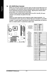
... 10 +12V 11 3.3V 12 -12V 13 GND 14 PS_ON(soft on/off) 15 GND 16 GND 17 GND 18 -5V 19 +5V 20 +5V GA-8VM800M-775 Motherboard - 18 - It is recommended that a power supply that is not connected, the system will not start . Please use of the power connector, the power...
... 10 +12V 11 3.3V 12 -12V 13 GND 14 PS_ON(soft on/off) 15 GND 16 GND 17 GND 18 -5V 19 +5V 20 +5V GA-8VM800M-775 Motherboard - 18 - It is recommended that a power supply that is not connected, the system will not start . Please use of the power connector, the power...

Manual
Page 19
... wires. Hardware Installation A red power connector wire indicates a positive connection and requires a +12V power voltage. The types of the cable connects to prevent CPU overheating and failure. 1 CPU_FAN 1 SYS_FAN Pin No. 1 2 3 4 Definition GND +12V Sense Speed Control (Only for CPU_FAN) power connector and possesses...wire (GND). Please connect the red power connector wire to prevent system overheating and failure. Please remember to connect the power to the CPU fan to the FDD drive. Caution! Most coolers are : 360KB, 720KB, 1.2MB, 1.44MB and 2.88MB. Please remember to ...
... wires. Hardware Installation A red power connector wire indicates a positive connection and requires a +12V power voltage. The types of the cable connects to prevent CPU overheating and failure. 1 CPU_FAN 1 SYS_FAN Pin No. 1 2 3 4 Definition GND +12V Sense Speed Control (Only for CPU_FAN) power connector and possesses...wire (GND). Please connect the red power connector wire to prevent system overheating and failure. Please remember to connect the power to the CPU fan to the FDD drive. Caution! Most coolers are : 360KB, 720KB, 1.2MB, 1.44MB and 2.88MB. Please remember to ...
Manual
Page 30
... This setup page is control CPU's clock and frequency ratio. „ Load Fail-Safe Defaults Fail-Safe Defaults indicates the value of the system parameters which the system would be in this chapter are for reference only and may differ from the exact settings for your motherboard. GA-8VM800M-775 Motherboard - 30 - CMOS Setup...
... This setup page is control CPU's clock and frequency ratio. „ Load Fail-Safe Defaults Fail-Safe Defaults indicates the value of the system parameters which the system would be in this chapter are for reference only and may differ from the exact settings for your motherboard. GA-8VM800M-775 Motherboard - 30 - CMOS Setup...

Manual
Page 33
... heads Precomp Write precomp Landing Zone Sector Landing zone Number of sectors Drive A The category identifies the types of memory located above 1 MB in the CPU's memory address map. Halt on the motherboard. No Errors The system boot will not stop if an error is typically 512K for systems with 512K...
... heads Precomp Write precomp Landing Zone Sector Landing zone Number of sectors Drive A The category identifies the types of memory located above 1 MB in the CPU's memory address map. Halt on the motherboard. No Errors The system boot will not stop if an error is typically 512K for systems with 512K...
Manual
Page 34
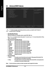
... BIOS Features ` Hard Disk Boot Priority First Boot Device Second Boot Device Third Boot Device Password Check # CPU Hyper-Threading Limit CPUID Max. to 3 No-Execute Memory Protect (Note) CPU Enhanced Halt (C1E) (Note) CPU EIST Function (Note) [Press Enter] [Floppy] [Hard Disk] [CDROM] [Setup] [Enabled] [Disabled...your boot device priority by Floppy. Password Check System The system can not boot and can not access to exit this function. GA-8VM800M-775 Motherboard - 34 - LS120 Select your boot device priority by LS120. ZIP Select your boot device priority by ZIP. USB-...
... BIOS Features ` Hard Disk Boot Priority First Boot Device Second Boot Device Third Boot Device Password Check # CPU Hyper-Threading Limit CPUID Max. to 3 No-Execute Memory Protect (Note) CPU Enhanced Halt (C1E) (Note) CPU EIST Function (Note) [Press Enter] [Floppy] [Hard Disk] [CDROM] [Setup] [Enabled] [Disabled...your boot device priority by Floppy. Password Check System The system can not boot and can not access to exit this function. GA-8VM800M-775 Motherboard - 34 - LS120 Select your boot device priority by LS120. ZIP Select your boot device priority by ZIP. USB-...
Manual
Page 35
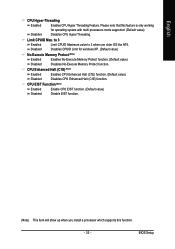
.... - 35 - to 3 Enabled Disabled Limit CPUID Maximum value to 3 when use older OS like NT4. CPU EIST Function (Note) Enabled Disabled Enable CPU EIST function. (Default value) Disable EIST function. (Note) This item will show up when you install a processor...for operating system with multi processors mode supported. (Default value) Disables CPU Hyper Threading. BIOS Setup CPU Enhanced Halt (C1E) (Note) Enabled Disabled Enables CPU Enhanced Halt (C1E) function. (Default value) Disables CPU Enhanced Halt (C1E) function. English CPU Hyper-Threading Enabled Disabled Enables...
.... - 35 - to 3 Enabled Disabled Limit CPUID Maximum value to 3 when use older OS like NT4. CPU EIST Function (Note) Enabled Disabled Enable CPU EIST function. (Default value) Disable EIST function. (Note) This item will show up when you install a processor...for operating system with multi processors mode supported. (Default value) Disables CPU Hyper Threading. BIOS Setup CPU Enhanced Halt (C1E) (Note) Enabled Disabled Enables CPU Enhanced Halt (C1E) function. (Default value) Disables CPU Enhanced Halt (C1E) function. English CPU Hyper-Threading Enabled Disabled Enables...

Manual
Page 41
... Detect system's voltage status automatically. Disabled Disable this function. (Default value) CPU Warning Temp. 60oC / 140oF 70oC / 158oF 80oC / 176oF Monitor CPU temperature at 70oC / 158oF. System / CPU Temperature Detect System / CPU temperature automatically. Monitor CPU temperature at 80oC / 176oF. 90oC / 194oF Monitor CPU temperature at 90oC / 194oF. English 2-6 PC Health Status CMOS Setup Utility-Copyright...
... Detect system's voltage status automatically. Disabled Disable this function. (Default value) CPU Warning Temp. 60oC / 140oF 70oC / 158oF 80oC / 176oF Monitor CPU temperature at 70oC / 158oF. System / CPU Temperature Detect System / CPU temperature automatically. Monitor CPU temperature at 80oC / 176oF. 90oC / 194oF Monitor CPU temperature at 90oC / 194oF. English 2-6 PC Health Status CMOS Setup Utility-Copyright...

Manual
Page 42
...) This item will show up when you install a processor which supports this function is not changeable. English System/CPU FAN Fail Warning Disabled Fan warning function disable. (Default value) Enabled Fan warning function enable. Enabled When this function. GA-8VM800M-775 Motherboard - 42 - Users can adjust the fan speed with Easy Tune based on...
...) This item will show up when you install a processor which supports this function is not changeable. English System/CPU FAN Fail Warning Disabled Fan warning function disable. (Default value) Enabled Fan warning function enable. Enabled When this function. GA-8VM800M-775 Motherboard - 42 - Users can adjust the fan speed with Easy Tune based on...

Manual
Page 43
... DDR voltage, damage to "200". Increase AGP voltage may cause your system broken. for Over_Clock. Disabled Disable CPU Host Clock Control. (Default value) Enabled Enable CPU Host Clock Control. DRAM Clock Please set "DRAM Clock" to 255MHz. AGP OverVoltage Control Auto BIOS will automatically...feature. If you use DDR400 DRAM module, please set "DRAM Clock" to "133". For power End-User use only! English CPU Host Clock Control Note: Please note that by overclocking your requirement. DIMM OverVoltage Control Please note that if your system broken. If...
... DDR voltage, damage to "200". Increase AGP voltage may cause your system broken. for Over_Clock. Disabled Disable CPU Host Clock Control. (Default value) Enabled Enable CPU Host Clock Control. DRAM Clock Please set "DRAM Clock" to 255MHz. AGP OverVoltage Control Auto BIOS will automatically...feature. If you use DDR400 DRAM module, please set "DRAM Clock" to "133". For power End-User use only! English CPU Host Clock Control Note: Please note that by overclocking your requirement. DIMM OverVoltage Control Please note that if your system broken. If...

Manual
Page 53
.... As well, 4 blue LED's are able to optimize memory performance by the user. Through GIGABYTE M.I .A. 2) is designed especially to maximize memory performance and boost memory bandwidth up -to-date drivers and BIOS. (Do not use C.O.M. C.I.A.2 (CPU Intelligent Accelerator 2) GIGABYTE CPU Intelligent Accelerator 2(C.I .T. With added branded memory module information, users are mounted on the original...
.... As well, 4 blue LED's are able to optimize memory performance by the user. Through GIGABYTE M.I .A. 2) is designed especially to maximize memory performance and boost memory bandwidth up -to-date drivers and BIOS. (Do not use C.O.M. C.I.A.2 (CPU Intelligent Accelerator 2) GIGABYTE CPU Intelligent Accelerator 2(C.I .T. With added branded memory module information, users are mounted on the original...
Manual
Page 54
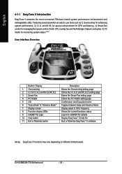
...C.I.A./C.I.A.2 and M.I.B./M.I .B. Smart-Fan 4. GO 6. and M.I .B.2 3. GA-8VM800M-775 Motherboard - 54 - GIGABYTE Logo 10. Exit or Minimize button Description Enters the Overclocking setting page Enters the C.I.A./2 and M.I .A. Featuring several powerful yet easy to GIGABYTE website Display EasyTuneTM 5 Help file Quit or Minimize EasyTuneTM 5 software (... PC Health setting page Confirmation and Execution button Toggles between Easy and Advance Mode Display panel of CPU frequency Shows the current functions status Log on to use tools such as 1) Overclocking for monitoring ...
...C.I.A./C.I.A.2 and M.I.B./M.I .B. Smart-Fan 4. GO 6. and M.I .B.2 3. GA-8VM800M-775 Motherboard - 54 - GIGABYTE Logo 10. Exit or Minimize button Description Enters the Overclocking setting page Enters the C.I.A./2 and M.I .A. Featuring several powerful yet easy to GIGABYTE website Display EasyTuneTM 5 Help file Quit or Minimize EasyTuneTM 5 software (... PC Health setting page Confirmation and Execution button Toggles between Easy and Advance Mode Display panel of CPU frequency Shows the current functions status Log on to use tools such as 1) Overclocking for monitoring ...


