
Manual
Page 1
...your data. 2. Installing a conventional SATA hard disk and a solid-state drive (SSD): Besides the conventional SATA disk, you have and the BIOS version. - 1 - Set PCH SATA Control Mode under the Integrated Peripherals menu to the SATA disk 4. Installing the operating system and drivers... to RAID(XHD). Installing a conventional SATA hard disk and a solid-state drive (SSD) 2. Then save changes and exit BIOS Setup. The maximum cache memory size is recommended that you have installed the operating system before enabling the Smart Response Technology. 1. Enabling RAID...
...your data. 2. Installing a conventional SATA hard disk and a solid-state drive (SSD): Besides the conventional SATA disk, you have and the BIOS version. - 1 - Set PCH SATA Control Mode under the Integrated Peripherals menu to the SATA disk 4. Installing the operating system and drivers... to RAID(XHD). Installing a conventional SATA hard disk and a solid-state drive (SSD) 2. Then save changes and exit BIOS Setup. The maximum cache memory size is recommended that you have installed the operating system before enabling the Smart Response Technology. 1. Enabling RAID...

Manual
Page 2
English 3. Installing the operating system and drivers to the SATA disk: After setting the BIOS, you can begin to install all motherboard drivers, including the Intel Rapid Storage Technology driver. After the installation is 10.5 or above and restarting your ...
English 3. Installing the operating system and drivers to the SATA disk: After setting the BIOS, you can begin to install all motherboard drivers, including the Intel Rapid Storage Technology driver. After the installation is 10.5 or above and restarting your ...
Manual
Page 3
... transmitted, or published in any form or by any means without prior notice. No part of this manual is protected by GIGABYTE without GIGABYTE's prior written permission. Documentation Classifications In order to their respective owners. All rights reserved. For example, "REV: 1.0" means...: X.X." For product-related information, check on our website at: http://www.gigabyte.com Identifying Your Motherboard Revision The revision number on your motherboard revision before updating motherboard BIOS, drivers, or when looking for technical information. Changes to the specifications and ...
... transmitted, or published in any form or by any means without prior notice. No part of this manual is protected by GIGABYTE without GIGABYTE's prior written permission. Documentation Classifications In order to their respective owners. All rights reserved. For example, "REV: 1.0" means...: X.X." For product-related information, check on our website at: http://www.gigabyte.com Identifying Your Motherboard Revision The revision number on your motherboard revision before updating motherboard BIOS, drivers, or when looking for technical information. Changes to the specifications and ...
Manual
Page 4
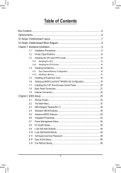
Table of Contents Box Contents...6 Optional Items...6 G1.Sniper 2 Motherboard Layout 7 G1.Sniper 2 Motherboard Block Diagram 8 Chapter 1 Hardware Installation 9 1-1 Installation Precautions 9 1-2 Product Specifications 10 1-3 Installing the CPU and CPU ...Front Access Control Panel 20 1-8 Back Panel Connectors 21 1-9 Internal Connectors 23 Chapter 2 BIOS Setup 35 2-1 Startup Screen 36 2-2 The Main Menu 37 2-3 MB Intelligent Tweaker(M.I.T 39 2-4 Standard CMOS Features 48 2-5 Advanced BIOS Features 50 2-6 Integrated Peripherals 52 2-7 Power Management Setup 54 2-8 PC Health Status ...
Table of Contents Box Contents...6 Optional Items...6 G1.Sniper 2 Motherboard Layout 7 G1.Sniper 2 Motherboard Block Diagram 8 Chapter 1 Hardware Installation 9 1-1 Installation Precautions 9 1-2 Product Specifications 10 1-3 Installing the CPU and CPU ...Front Access Control Panel 20 1-8 Back Panel Connectors 21 1-9 Internal Connectors 23 Chapter 2 BIOS Setup 35 2-1 Startup Screen 36 2-2 The Main Menu 37 2-3 MB Intelligent Tweaker(M.I.T 39 2-4 Standard CMOS Features 48 2-5 Advanced BIOS Features 50 2-6 Integrated Peripherals 52 2-7 Power Management Setup 54 2-8 PC Health Status ...
Manual
Page 5
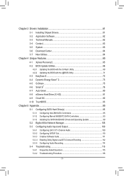
... 62 3-4 Contact...63 3-5 System...63 3-6 Download Center 64 3-7 New Utilities...64 Chapter 4 Unique Features 65 4-1 Xpress Recovery2 65 4-2 BIOS Update Utilities 68 4-2-1 Updating the BIOS with the Q-Flash Utility 68 4-2-2 Updating the BIOS with the @BIOS Utility 71 4-3 EasyTune 6...72 4-4 Dynamic Energy Saver™ 2 73 4-5 Q-Share...75 4-6 Smart 6™ ...76 4-7 Auto Green...80 4-8 eXtreme...
... 62 3-4 Contact...63 3-5 System...63 3-6 Download Center 64 3-7 New Utilities...64 Chapter 4 Unique Features 65 4-1 Xpress Recovery2 65 4-2 BIOS Update Utilities 68 4-2-1 Updating the BIOS with the Q-Flash Utility 68 4-2-2 Updating the BIOS with the @BIOS Utility 71 4-3 EasyTune 6...72 4-4 Dynamic Energy Saver™ 2 73 4-5 Q-Share...75 4-6 Smart 6™ ...76 4-7 Auto Green...80 4-8 eXtreme...
Manual
Page 8
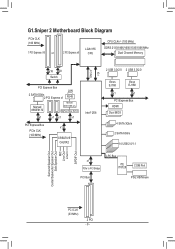
G1.Sniper 2 Motherboard Block Diagram PCIe CLK (100 MHz) 1 PCI Express x16 or 2 PCI Express x8 LGA1155 CPU CPU CLK+/- (100 MHz) DDR3 2133/1866/1600/... PCIe CLK (100 MHz) x1 CREATIVE CA20K2 Intel® Z68 DMI 2.0 FDI 2 USB 3.0/2.0 2 USB 3.0/2.0 Etron EJ168 Etron EJ168 x1 x1 PCI Express Bus HDMI Dual BIOS 4 SATA 3Gb/s 2 SATA 6Gb/s 14 USB 2.0/1.1 x1 PCIe to PCI Bridge LPC Bus iTE IT8728 COM Port PCI Bus PS/2 KB/Mouse Surround Speaker Out...
G1.Sniper 2 Motherboard Block Diagram PCIe CLK (100 MHz) 1 PCI Express x16 or 2 PCI Express x8 LGA1155 CPU CPU CLK+/- (100 MHz) DDR3 2133/1866/1600/... PCIe CLK (100 MHz) x1 CREATIVE CA20K2 Intel® Z68 DMI 2.0 FDI 2 USB 3.0/2.0 2 USB 3.0/2.0 Etron EJ168 Etron EJ168 x1 x1 PCI Express Bus HDMI Dual BIOS 4 SATA 3Gb/s 2 SATA 6Gb/s 14 USB 2.0/1.1 x1 PCIe to PCI Bridge LPC Bus iTE IT8728 COM Port PCI Bus PS/2 KB/Mouse Surround Speaker Out...
Manual
Page 12
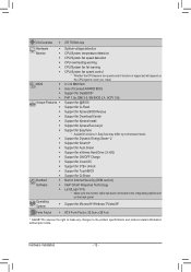
...flash ŠŠ Use of licensed AWARD BIOS ŠŠ Support for DualBIOS™ ŠŠ PnP 1.0a, DMI 2.0, SM BIOS 2.4, ACPI 1.0b Unique Features ŠŠ Support for @BIOS ŠŠ Support for Q-Flash ŠŠ Support for Xpress BIOS Rescue ŠŠ Support for Download Center ...ŠŠ Support for Microsoft® Windows 7/Vista/XP Form Factor ŠŠ ATX Form Factor; 30.5cm x 26.4cm * GIGABYTE reserves the right to make any changes to the integrated graphics port on the CPU/system cooler you install. Hardware Installation - 12 - I/O ...
...flash ŠŠ Use of licensed AWARD BIOS ŠŠ Support for DualBIOS™ ŠŠ PnP 1.0a, DMI 2.0, SM BIOS 2.4, ACPI 1.0b Unique Features ŠŠ Support for @BIOS ŠŠ Support for Q-Flash ŠŠ Support for Xpress BIOS Rescue ŠŠ Support for Download Center ...ŠŠ Support for Microsoft® Windows 7/Vista/XP Form Factor ŠŠ ATX Form Factor; 30.5cm x 26.4cm * GIGABYTE reserves the right to make any changes to the integrated graphics port on the CPU/system cooler you install. Hardware Installation - 12 - I/O ...
Manual
Page 16
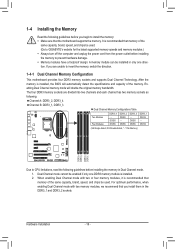
It is installed, the BIOS will double the original memory bandwidth. Dual Channel mode cannot be installed in the DDR3_1 and DDR3_2 sockets. After the memory is recommended that memory of the same capacity, brand, speed, and chips be used . (Go to GIGABYTE's website for the latest supported memory speeds and memory modules...
It is installed, the BIOS will double the original memory bandwidth. Dual Channel mode cannot be installed in the DDR3_1 and DDR3_2 sockets. After the memory is recommended that memory of the same capacity, brand, speed, and chips be used . (Go to GIGABYTE's website for the latest supported memory speeds and memory modules...
Manual
Page 18
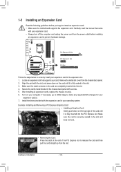
...expansion card in your expansion card. • Always turn off the computer and unplug the power cord from the slot. If necessary, go to BIOS Setup to the chassis back panel with your operating system. Hardware Installation - 18 - 1-5 Installing an Expansion Card Read the following guidelines before ...supports your computer. Make sure the card is fully inserted into the slot. 444 Secure the card's metal bracket to make any required BIOS changes for your expansion card(s). 777 Install the driver provided with the expansion card in the expansion slot. 111 Locate an expansion slot ...
...expansion card in your expansion card. • Always turn off the computer and unplug the power cord from the slot. If necessary, go to BIOS Setup to the chassis back panel with your operating system. Hardware Installation - 18 - 1-5 Installing an Expansion Card Read the following guidelines before ...supports your computer. Make sure the card is fully inserted into the slot. 444 Secure the card's metal bracket to make any required BIOS changes for your expansion card(s). 777 Install the driver provided with the expansion card in the expansion slot. 111 Locate an expansion slot ...
Manual
Page 28
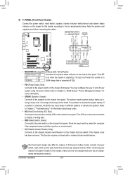
... panel module to this header according to the pin assignments below. One single short beep will be heard if no problem is detected, the BIOS may differ by issuing a beep code. Refer to Chapter 5, "Troubleshooting," for more information). •• SPEAK (Speaker, Orange): Connects... panel. Note the positive and negative pins before connecting the cables. When connecting your system using the power switch (refer to Chapter 2, "BIOS Setup," "Power Management Setup," for information about beep codes. •• HD (Hard Drive Activity LED, Blue) Connects to the hard...
... panel module to this header according to the pin assignments below. One single short beep will be heard if no problem is detected, the BIOS may differ by issuing a beep code. Refer to Chapter 5, "Troubleshooting," for more information). •• SPEAK (Speaker, Orange): Connects... panel. Note the positive and negative pins before connecting the cables. When connecting your system using the power switch (refer to Chapter 2, "BIOS Setup," "Power Management Setup," for information about beep codes. •• HD (Hard Drive Activity LED, Blue) Connects to the hard...
Manual
Page 31
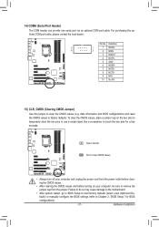
...4 NDTR- 5 GND 6 NDSR- 7 NRTS- 8 NCTS- 9 NRI- 10 No Pin 15) CLR_CMOS (Clearing CMOS Jumper) Use this jumper to factory defaults. date information and BIOS configurations) and reset the CMOS values to clear the CMOS values (e.g. Hardware Installation Open: Normal Short: Clear CMOS Values •• Always turn off your... turning on the two pins to temporarily short the two pins or use a metal object like a screwdriver to touch the two pins for BIOS configurations). - 31 - 14) COMA (Serial Port Header) The COM header can provide one serial port via an optional COM port cable....
...4 NDTR- 5 GND 6 NDSR- 7 NRTS- 8 NCTS- 9 NRI- 10 No Pin 15) CLR_CMOS (Clearing CMOS Jumper) Use this jumper to factory defaults. date information and BIOS configurations) and reset the CMOS values to clear the CMOS values (e.g. Hardware Installation Open: Normal Short: Clear CMOS Values •• Always turn off your... turning on the two pins to temporarily short the two pins or use a metal object like a screwdriver to touch the two pins for BIOS configurations). - 31 - 14) COMA (Serial Port Header) The COM header can provide one serial port via an optional COM port cable....
Manual
Page 32
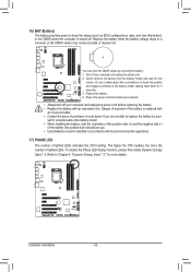
... the Phase LED display function, please first enable Dynamic Energy Saver™ 2. 16) BAT (Battery) The battery provides power to keep the values (such as BIOS configurations, date, and time information) in the CMOS when the computer is replaced with an incorrect model. •• Contact the place of purchase or...
... the Phase LED display function, please first enable Dynamic Energy Saver™ 2. 16) BAT (Battery) The battery provides power to keep the values (such as BIOS configurations, date, and time information) in the CMOS when the computer is replaced with an incorrect model. •• Contact the place of purchase or...
Manual
Page 33
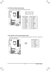
DB_PORT BIOS Switc 1 1 19 TPM w/housing 20 Pin No. 1 2 3 4 5 6 7 8 9 10 Definition LCLK GND LFRAME No Pin LRESET NC LAD3 LAD2 VCC3 LAD1 1 Voltage measurement module(X58A-OC) ...
DB_PORT BIOS Switc 1 1 19 TPM w/housing 20 Pin No. 1 2 3 4 5 6 7 8 9 10 Definition LCLK GND LFRAME No Pin LRESET NC LAD3 LAD2 VCC3 LAD1 1 Voltage measurement module(X58A-OC) ...
Manual
Page 35
... operating system, etc. Inadequately altering the settings may result in this chapter or introductions of BIOS from the Internet and updates the BIOS. To upgrade the BIOS, use either the GIGABYTE Q-Flash or @BIOS utility. • Q-Flash allows the user to quickly and easily upgrade or back up... BIOS without entering the operating system. • @BIOS is a Windows-based utility that you do it is ...
... operating system, etc. Inadequately altering the settings may result in this chapter or introductions of BIOS from the Internet and updates the BIOS. To upgrade the BIOS, use either the GIGABYTE Q-Flash or @BIOS utility. • Q-Flash allows the user to quickly and easily upgrade or back up... BIOS without entering the operating system. • @BIOS is a Windows-based utility that you do it is ...
Manual
Page 36
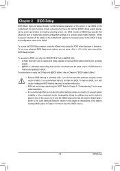
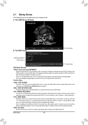
...ever entered Xpress Recovery2 to its default values, the monitor will still be used for one time only. Motherboard Model BIOS Version G1.Sniper 2 F1c . . . . To show the BIOS POST screen. To exit Boot Menu, press . After system restart, the device boot order will display a message ...change it to accept. The system will appear again at IDE MODE!" A. When the motherboard is effective for subsequent access to enter BIOS Setup first. BIOS Setup - 36 - 2-1 Startup Screen The following screens may appear when the computer boots. The LOGO Screen (Default) B. The ...
...ever entered Xpress Recovery2 to its default values, the monitor will still be used for one time only. Motherboard Model BIOS Version G1.Sniper 2 F1c . . . . To show the BIOS POST screen. To exit Boot Menu, press . After system restart, the device boot order will display a message ...change it to accept. The system will appear again at IDE MODE!" A. When the motherboard is effective for subsequent access to enter BIOS Setup first. BIOS Setup - 36 - 2-1 Startup Screen The following screens may appear when the computer boots. The LOGO Screen (Default) B. The ...
Manual
Page 37
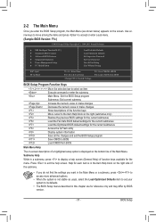
... Saving ESC: Quit F8: Q-Flash Select Item F10: Save & Exit Setup Change CPU's Clock & Voltage F11: Save CMOS to BIOS F12: Load CMOS from BIOS BIOS Setup Program Function Keys Move the selection bar to select an item Execute command or enter the submenu Main Menu: Exit the... settings for the current submenus Access the Q-Flash utility Display system information Save all the changes and exit the BIOS Setup program Save CMOS to BIOS Load CMOS from BIOS Main Menu Help The on-screen description of a highlighted setup option is displayed on the screen. 2-2 The...
... Saving ESC: Quit F8: Q-Flash Select Item F10: Save & Exit Setup Change CPU's Clock & Voltage F11: Save CMOS to BIOS F12: Load CMOS from BIOS BIOS Setup Program Function Keys Move the selection bar to select an item Execute command or enter the submenu Main Menu: Exit the... settings for the current submenus Access the Q-Flash utility Display system information Save all the changes and exit the BIOS Setup program Save CMOS to BIOS Load CMOS from BIOS Main Menu Help The on-screen description of a highlighted setup option is displayed on the screen. 2-2 The...
Manual
Page 38
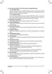
...to configure the system time and date, hard drive types, and the type of errors that stop the system boot, etc. Advanced BIOS Features Use this menu to configure the device boot order, advanced features available on the CPU, and the primary display adapter. Integrated ... previous settings remain in effect. First enter the profile name (to erase the default profile name, use this menu to the confirmation message will exit BIOS Setup. (Pressing can create up to 8 profiles (Profile 1-8) and name each profile. First select the profile you wish to load, then press ...
...to configure the system time and date, hard drive types, and the type of errors that stop the system boot, etc. Advanced BIOS Features Use this menu to configure the device boot order, advanced features available on the CPU, and the primary display adapter. Integrated ... previous settings remain in effect. First enter the profile name (to erase the default profile name, use this menu to the confirmation message will exit BIOS Setup. (Pressing can create up to 8 profiles (Profile 1-8) and name each profile. First select the profile you wish to load, then press ...
Manual
Page 39
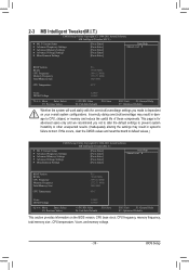
... } Miscellaneous Settings [Press Enter] [Press Enter] [Press Enter] [Press Enter] [Press Enter] Item Help Menu Level BIOS Version BCLK CPU Frequency Memory Frequency Total Memory Size CPU Temperature F1c 99.80 MHz 3094.12 MHz 1332.71 MHz 1024 MB 45oC ... } Miscellaneous Settings [Press Enter] [Press Enter] [Press Enter] [Press Enter] [Press Enter] Item Help Menu Level BIOS Version BCLK CPU Frequency Memory Frequency Total Memory Size CPU Temperature F1c 99.80 MHz 3094.12 MHz 1332.71 MHz 1024 MB 45oC ...
... } Miscellaneous Settings [Press Enter] [Press Enter] [Press Enter] [Press Enter] [Press Enter] Item Help Menu Level BIOS Version BCLK CPU Frequency Memory Frequency Total Memory Size CPU Temperature F1c 99.80 MHz 3094.12 MHz 1332.71 MHz 1024 MB 45oC ... } Miscellaneous Settings [Press Enter] [Press Enter] [Press Enter] [Press Enter] [Press Enter] Item Help Menu Level BIOS Version BCLK CPU Frequency Memory Frequency Total Memory Size CPU Temperature F1c 99.80 MHz 3094.12 MHz 1332.71 MHz 1024 MB 45oC ...
Manual
Page 40
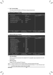
...; M.I.T. CPU Frequency Displays the current operating CPU frequency. (Note 1) This item is present only if you to alter the clock ratio for the installed CPU. BIOS Setup - 40 - The adjustable range is dependent on CPU/memory frequencies/parameters. Advanced Frequency Settings CMOS Setup Utility-Copyright (C) 1984-2011 Award Software Advanced...
...; M.I.T. CPU Frequency Displays the current operating CPU frequency. (Note 1) This item is present only if you to alter the clock ratio for the installed CPU. BIOS Setup - 40 - The adjustable range is dependent on CPU/memory frequencies/parameters. Advanced Frequency Settings CMOS Setup Utility-Copyright (C) 1984-2011 Award Software Advanced...

Manual
Page 41
... you to alter the PWM frequency. For more information about Intel CPUs' unique features, please visit Intel's website. - 41 - Auto lets the BIOS automatically configure this setting. (Default: Auto) Intel(R) Turbo Boost Tech. (Note) Allows you to set the CPU Turbo ratios for CPU over-current...cores. (Default) 1 Enables only one CPU core. 2 Enables only two CPU cores. 3 Enables only three CPU cores. Auto lets the BIOS automatically configure this setting. (Default: Auto) CPU Over Current Protection Allows you to determine whether to enable the Intel CPU Turbo Boost technology. ...
... you to alter the PWM frequency. For more information about Intel CPUs' unique features, please visit Intel's website. - 41 - Auto lets the BIOS automatically configure this setting. (Default: Auto) Intel(R) Turbo Boost Tech. (Note) Allows you to set the CPU Turbo ratios for CPU over-current...cores. (Default) 1 Enables only one CPU core. 2 Enables only two CPU cores. 3 Enables only three CPU cores. Auto lets the BIOS automatically configure this setting. (Default: Auto) CPU Over Current Protection Allows you to determine whether to enable the Intel CPU Turbo Boost technology. ...


