
Manual
Page 1
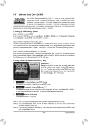
... Core series CPU. • The operating system must be installed to enter BIOS Setup during the POST (Power-On Self-Test). If you use an SSD larger than 64 GB, the space beyond 64 GB can still be lost once you enable RAID mode. CMOS Setup Utility-Copyright (C) 1984-2011 Award Software Integrated Peripherals eXtreme Hard Drive (XHD) PCH SATA Control Mode OROM UI and Banner SATA Port0-3 Native Mode USB Controllers USB Legacy Function USB Storage Function Azalia Codec Onboard H/W 1394 Onboard H/W LAN } SMART LAN Onboard LAN Boot ROM...
... Core series CPU. • The operating system must be installed to enter BIOS Setup during the POST (Power-On Self-Test). If you use an SSD larger than 64 GB, the space beyond 64 GB can still be lost once you enable RAID mode. CMOS Setup Utility-Copyright (C) 1984-2011 Award Software Integrated Peripherals eXtreme Hard Drive (XHD) PCH SATA Control Mode OROM UI and Banner SATA Port0-3 Native Mode USB Controllers USB Legacy Function USB Storage Function Azalia Codec Onboard H/W 1394 Onboard H/W LAN } SMART LAN Onboard LAN Boot ROM...
Manual
Page 4
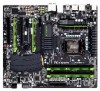
... Layout 7 G1.Sniper 2 Motherboard Block Diagram 8 Chapter 1 Hardware Installation 9 1-1 Installation Precautions 9 1-2 Product Specifications 10 1-3 Installing the CPU and CPU Cooler 13 1-3-1 Installing the CPU 13 1-3-2 Installing the CPU Cooler 15 1-4 Installing the Memory 16 1-4-1 Dual Channel Memory Configuration 16 1-4-2 Installing a Memory 17 1-5 Installing an Expansion Card 18 1-6 Setting up AMD CrossFireX™/NVIDIA SLI Configuration 19 1-7 Installing the 5.25" Front Access Control Panel 20 1-8 Back Panel Connectors 21 1-9 Internal Connectors 23 Chapter 2 BIOS Setup...
... Layout 7 G1.Sniper 2 Motherboard Block Diagram 8 Chapter 1 Hardware Installation 9 1-1 Installation Precautions 9 1-2 Product Specifications 10 1-3 Installing the CPU and CPU Cooler 13 1-3-1 Installing the CPU 13 1-3-2 Installing the CPU Cooler 15 1-4 Installing the Memory 16 1-4-1 Dual Channel Memory Configuration 16 1-4-2 Installing a Memory 17 1-5 Installing an Expansion Card 18 1-6 Setting up AMD CrossFireX™/NVIDIA SLI Configuration 19 1-7 Installing the 5.25" Front Access Control Panel 20 1-8 Back Panel Connectors 21 1-9 Internal Connectors 23 Chapter 2 BIOS Setup...
Manual
Page 20
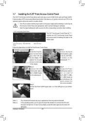
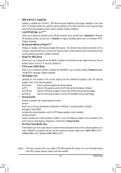
... USB Connect the Power 3.0/2.0 ports' cable to eSATA power cable to the F_USB30 header Pin 1, 3, 5, and 7 of your mother- Connect the Power eSATA signal cable to the defaults, press the button again and the button will light red. To return to a free SATA port on the motherboard. It also provides a CPU overclocking (Quick Boost) button that allows you can press the Quick Boost button to the chassis sides. CPU Overclocking Power eSATA Port Button USB 3.0/2.0 Ports Follow the steps below to install the Front Access Control Panel...
... USB Connect the Power 3.0/2.0 ports' cable to eSATA power cable to the F_USB30 header Pin 1, 3, 5, and 7 of your mother- Connect the Power eSATA signal cable to the defaults, press the button again and the button will light red. To return to a free SATA port on the motherboard. It also provides a CPU overclocking (Quick Boost) button that allows you can press the Quick Boost button to the chassis sides. CPU Overclocking Power eSATA Port Button USB 3.0/2.0 Ports Follow the steps below to install the Front Access Control Panel...
Manual
Page 21
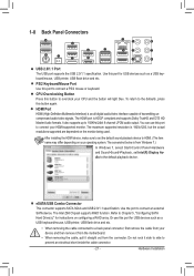
...Windows 7, select Start>Control Panel>Hardware and Sound>Sound>Playback, set the default sound playback device to a back panel connector, first remove the cable from your HDMI-supported monitor. After installing the HDMI device, make sure to set Intel(R) Display Audio to connect your device and then remove it from the connector. Hardware Installation eSATA/USB Combo Connector This connector supports SATA 3Gb/s and USB 2.0/1.1 specification. Use the port to connect a PS/2 mouse or keyboard. Or use this port for USB devices such as a USB keyboard/mouse, USB printer, USB flash drive...
...Windows 7, select Start>Control Panel>Hardware and Sound>Sound>Playback, set the default sound playback device to a back panel connector, first remove the cable from your HDMI-supported monitor. After installing the HDMI device, make sure to set Intel(R) Display Audio to connect your device and then remove it from the connector. Hardware Installation eSATA/USB Combo Connector This connector supports SATA 3Gb/s and USB 2.0/1.1 specification. Use the port to connect a PS/2 mouse or keyboard. Or use this port for USB devices such as a USB keyboard/mouse, USB printer, USB flash drive...
Manual
Page 31
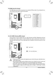
... optional COM port cable. Definition 9 1 1 NDCD- 10 2 2 NSIN 3 NSOUT 4 NDTR- 5 GND 6 NDSR- 7 NRTS- 8 NCTS- 9 NRI- 10 No Pin 15) CLR_CMOS (Clearing CMOS Jumper) Use this jumper to factory defaults. date information and BIOS configurations) and reset the CMOS values to clear the CMOS values (e.g. Hardware Installation Pin No. Failure to do so may cause damage to the motherboard. •• After system restart, go to BIOS Setup to load factory defaults (select Load Optimized Defaults) or manually configure...
... optional COM port cable. Definition 9 1 1 NDCD- 10 2 2 NSIN 3 NSOUT 4 NDTR- 5 GND 6 NDSR- 7 NRTS- 8 NCTS- 9 NRI- 10 No Pin 15) CLR_CMOS (Clearing CMOS Jumper) Use this jumper to factory defaults. date information and BIOS configurations) and reset the CMOS values to clear the CMOS values (e.g. Hardware Installation Pin No. Failure to do so may cause damage to the motherboard. •• After system restart, go to BIOS Setup to load factory defaults (select Load Optimized Defaults) or manually configure...
Manual
Page 36
... default values, the monitor will still be used for the SATA connectors. A. Motherboard Model BIOS Version G1.Sniper 2 F1c . . . . For more information, refer to Chapter 4, "Xpress Recovery2." : BOOT MENU Boot Menu allows you to set to the instructions on the Full Screen LOGO Show item on BIOS Setup settings. You can be based on page 51. : BIOS SETUP\Q-FLASH Press the key to enter BIOS Setup or to enter BIOS Setup first. Note: The setting in BIOS Setup. : XPRESS RECOVERY2 If you the SATA controller...
... default values, the monitor will still be used for the SATA connectors. A. Motherboard Model BIOS Version G1.Sniper 2 F1c . . . . For more information, refer to Chapter 4, "Xpress Recovery2." : BOOT MENU Boot Menu allows you to set to the instructions on the Full Screen LOGO Show item on BIOS Setup settings. You can be based on page 51. : BIOS SETUP\Q-FLASH Press the key to enter BIOS Setup or to enter BIOS Setup first. Note: The setting in BIOS Setup. : XPRESS RECOVERY2 If you the SATA controller...

Manual
Page 41
...operating systems that support multi-processor mode. (Default: Enabled) CPU Enhanced Halt (C1E) (Note) Enables or disables Intel CPU Enhanced Halt (C1E) function, a CPU power-saving function in BIOS setup. Auto lets the BIOS automatically configure this setting. (Default: Auto) Internal CPU PLL Overvoltage Enabled allows CPU PLL voltage to operate at a higher value. Auto lets the BIOS automatically configure this setting. (Default: Disabled) (Note) This item is from +60% to decrease power consumption. PWM Frequency Control Allows you install a CPU that supports this feature...
...operating systems that support multi-processor mode. (Default: Enabled) CPU Enhanced Halt (C1E) (Note) Enables or disables Intel CPU Enhanced Halt (C1E) function, a CPU power-saving function in BIOS setup. Auto lets the BIOS automatically configure this setting. (Default: Auto) Internal CPU PLL Overvoltage Enabled allows CPU PLL voltage to operate at a higher value. Auto lets the BIOS automatically configure this setting. (Default: Disabled) (Note) This item is from +60% to decrease power consumption. PWM Frequency Control Allows you install a CPU that supports this feature...
Manual
Page 42
... clear the CMOS values to reset the board to default values. (Default: Disabled) BCLK/DMI/PEG Frequency(0.1MHz) Allows you to determine whether to let the CPU enter C3/C6 mode in accordance with the CPU specifications. This item is configurable only if the BCLK/DMI/PEG Clock Control option is occurring, PROCHOT signals will be emitted to lower CPU performance to decrease heat production. Profile2 (Note 2) Uses Profile 2 settings. Auto sets memory...
... clear the CMOS values to reset the board to default values. (Default: Disabled) BCLK/DMI/PEG Frequency(0.1MHz) Allows you to determine whether to let the CPU enter C3/C6 mode in accordance with the CPU specifications. This item is configurable only if the BCLK/DMI/PEG Clock Control option is occurring, PROCHOT signals will be emitted to lower CPU performance to decrease heat production. Profile2 (Note 2) Uses Profile 2 settings. Auto sets memory...
Manual
Page 47
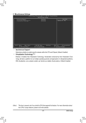
...BIOS Setup For more information about Intel CPUs' unique features, please visit Intel's website. - 47 - Virtualization enhanced by Intel Virtualization Technology will allow a platform to enable specific streams within the CPU and Chipset. (Default: Enabled) Virtualization Technology (Note) Enables or disables Intel Virtualization Technology. Miscellaneous Settings CMOS Setup Utility-Copyright (C) 1984-2011 Award Software Miscellaneous Settings Isochronous Support Virtualization Technology (Note) [Enabled] [Enabled] Item Help Menu Level Move Enter...
...BIOS Setup For more information about Intel CPUs' unique features, please visit Intel's website. - 47 - Virtualization enhanced by Intel Virtualization Technology will allow a platform to enable specific streams within the CPU and Chipset. (Default: Enabled) Virtualization Technology (Note) Enables or disables Intel Virtualization Technology. Miscellaneous Settings CMOS Setup Utility-Copyright (C) 1984-2011 Award Software Miscellaneous Settings Isochronous Support Virtualization Technology (Note) [Enabled] [Enabled] Item Help Menu Level Move Enter...
Manual
Page 50
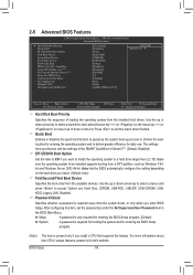
2-5 Advanced BIOS Features CMOS Setup Utility-Copyright (C) 1984-2011 Award Software Advanced BIOS Features } Hard Disk Boot Priority Quick Boot EFI CD/DVD Boot Option First Boot Device Second Boot Device Third Boot Device Password Check HDD S.M.A.R.T. Capability Limit CPUID Max. to 3 (Note) No-Execute Memory Protect (Note) Delay For HDD (Secs) Full Screen LOGO Show Init Display First Onboard VGA On-Chip Frame Buffer Size [Press Enter] [Disabled] [Auto] [Hard Disk] [CDROM] [USB-FDD] [Setup] [Disabled] [Disabled] [Enabled] [0] [Enabled] [PCI] [Auto]...
2-5 Advanced BIOS Features CMOS Setup Utility-Copyright (C) 1984-2011 Award Software Advanced BIOS Features } Hard Disk Boot Priority Quick Boot EFI CD/DVD Boot Option First Boot Device Second Boot Device Third Boot Device Password Check HDD S.M.A.R.T. Capability Limit CPUID Max. to 3 (Note) No-Execute Memory Protect (Note) Delay For HDD (Secs) Full Screen LOGO Show Init Display First Onboard VGA On-Chip Frame Buffer Size [Press Enter] [Disabled] [Auto] [Hard Disk] [CDROM] [USB-FDD] [Setup] [Disabled] [Disabled] [Enabled] [0] [Enabled] [PCI] [Auto]...
Manual
Page 51
.... (Default: 0) Full Screen LOGO Show Allows you install a CPU that supports this feature. Disabled displays normal POST message. (Default: Enabled) Init Display First Specifies the first initiation of system memory allocated solely for GTT) (Note) This item is installed. (Default: Disabled) Limit CPUID Max. On-Chip Frame Buffer Size Frame buffer size is installed. HDD S.M.A.R.T. Always Enable Always activates the onboard graphics, whether or not a PCI Express graphics card is the total amount of the monitor display from 0 to set up a dual-display configuration, set...
.... (Default: 0) Full Screen LOGO Show Allows you install a CPU that supports this feature. Disabled displays normal POST message. (Default: Enabled) Init Display First Specifies the first initiation of system memory allocated solely for GTT) (Note) This item is installed. (Default: Disabled) Limit CPUID Max. On-Chip Frame Buffer Size Frame buffer size is installed. HDD S.M.A.R.T. Always Enable Always activates the onboard graphics, whether or not a PCI Express graphics card is the total amount of the monitor display from 0 to set up a dual-display configuration, set...
Manual
Page 53
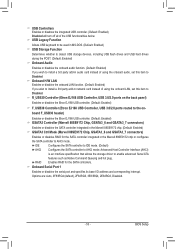
... USB Controller, USB 3.0/2.0 ports routed to enable advanced Serial ATA features such as Native Command Queuing and hot plug. USB Legacy Function Allows USB keyboard to be used in MS-DOS. (Default: Enabled) USB Storage Function Determines whether to detect USB storage devices, including USB flash drives and USB hard drives during the POST. (Default: Enabled) Onboard Audio Enables or disables the onboard audio function. (Default: Enabled) If you wish to install a 3rd party add-in network card instead of the USB functionalities below. IDE Configures the SATA controller to IDE mode...
... USB Controller, USB 3.0/2.0 ports routed to enable advanced Serial ATA features such as Native Command Queuing and hot plug. USB Legacy Function Allows USB keyboard to be used in MS-DOS. (Default: Enabled) USB Storage Function Determines whether to detect USB storage devices, including USB flash drives and USB hard drives during the POST. (Default: Enabled) Onboard Audio Enables or disables the onboard audio function. (Default: Enabled) If you wish to install a 3rd party add-in network card instead of the USB functionalities below. IDE Configures the SATA controller to IDE mode...
Manual
Page 69
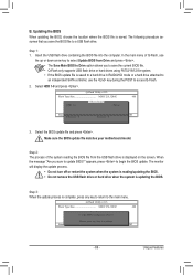
... to a hard drive in RAID/AHCI mode or a hard drive attached to an independent SATA controller, use the key during the POST to a USB flash drive. Update BIOS from Drive Save BIOS to the main menu. Q-Flash Utility v2.23 Flash Type/Size MXIC 25L3206E 4M Keep0 DfilMe(Is)DfaotuandEnable HDD 1-0 Loa d CMO S Default Enable Update BIOS from Drive Please SparevsesBaInOySketoy Dtoricvoentinue Enter : Run hi:Move ESC:Reset F10:Power Off - 69 - Step 3: When the update process is updating the BIOS. Insert the USB flash drive containing the BIOS file into the...
... to a hard drive in RAID/AHCI mode or a hard drive attached to an independent SATA controller, use the key during the POST to a USB flash drive. Update BIOS from Drive Save BIOS to the main menu. Q-Flash Utility v2.23 Flash Type/Size MXIC 25L3206E 4M Keep0 DfilMe(Is)DfaotuandEnable HDD 1-0 Loa d CMO S Default Enable Update BIOS from Drive Please SparevsesBaInOySketoy Dtoricvoentinue Enter : Run hi:Move ESC:Reset F10:Power Off - 69 - Step 3: When the update process is updating the BIOS. Insert the USB flash drive containing the BIOS file into the...
Manual
Page 81
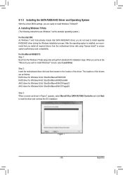
... set up a RAID 0 array later using the Auto function. - 81 - Unique Features To automatically set up a RAID 0 array. 2. Setting Up a RAID-Ready System Step 1: Configure the system BIOS Enter the system BIOS Setup program, set up a RAID-ready system and configure it for the Intel SATA controllers. Before installing the operating system, you have to enable RAID for RAID 0. Step 2: Install the RAID driver and operating system The X.H.D utility supports Windows 7/Vista/XP. You can build a RAID 0, RAID 1, or other supported RAID...
... set up a RAID 0 array later using the Auto function. - 81 - Unique Features To automatically set up a RAID 0 array. 2. Setting Up a RAID-Ready System Step 1: Configure the system BIOS Enter the system BIOS Setup program, set up a RAID-ready system and configure it for the Intel SATA controllers. Before installing the operating system, you have to enable RAID for RAID 0. Step 2: Install the RAID driver and operating system The X.H.D utility supports Windows 7/Vista/XP. You can build a RAID 0, RAID 1, or other supported RAID...
Manual
Page 85
... the SATA signal cable to identify the SATA controller for the SATA port. (For example, on the devices being connected. - 85 - mance of the SATA hard drive and the other end to create RAID, you use two hard drives with identical model and capacity). Configure SATA controller mode in RAID BIOS. (Note 1) D. If you do not want to available SATA port on the motherboard. Appendix Configure a RAID array in BIOS Setup. B. Install the SATA RAID/AHCI driver (Note 2) and operating system. Chapter 5 Appendix 5-1 Configuring SATA Hard Drive(s) To configure SATA hard drive...
... the SATA signal cable to identify the SATA controller for the SATA port. (For example, on the devices being connected. - 85 - mance of the SATA hard drive and the other end to create RAID, you use two hard drives with identical model and capacity). Configure SATA controller mode in RAID BIOS. (Note 1) D. If you do not want to available SATA port on the motherboard. Appendix Configure a RAID array in BIOS Setup. B. Install the SATA RAID/AHCI driver (Note 2) and operating system. Chapter 5 Appendix 5-1 Configuring SATA Hard Drive(s) To configure SATA hard drive...
Manual
Page 99
.../AHCI driver during the Windows installation process. screen, select Load Driver. For the Marvell 88SE9172: Step 1: Boot from the motherboard driver disk using "Xpress Install" to the location of the drivers are ready to install Windows 7/Vista/XP. Appendix 5-1-3 Installing the SATA RAID/AHCI Driver and Operating System With the correct BIOS settings, you are as follows: RAID driver for Windows 32-bit: \BootDrv\Marvell\RAID\i386 RAID driver for Windows 64-bit: \BootDrv\Marvell\RAID\amd64 AHCI driver for Windows 32-bit: \BootDrv\Marvell\AHCI\Floppy32 AHCI driver for Windows 64-bit...
.../AHCI driver during the Windows installation process. screen, select Load Driver. For the Marvell 88SE9172: Step 1: Boot from the motherboard driver disk using "Xpress Install" to the location of the drivers are ready to install Windows 7/Vista/XP. Appendix 5-1-3 Installing the SATA RAID/AHCI Driver and Operating System With the correct BIOS settings, you are as follows: RAID driver for Windows 32-bit: \BootDrv\Marvell\RAID\i386 RAID driver for Windows 64-bit: \BootDrv\Marvell\RAID\amd64 AHCI driver for Windows 32-bit: \BootDrv\Marvell\AHCI\Floppy32 AHCI driver for Windows 64-bit...

Manual
Page 100
... the floppy disk. Without the driver, the hard drive(s) may not be recognized during the OS installation. Installing Windows XP Before installing Windows XP, connect a USB floppy disk drive to your optical drive folder, double click the Menu.exe file in Figure 2, • For the Intel Z68, select 8) Intel Rapid Storage driver for 32bit system for Windows XP 32-bit op- B. A Command Prompt window will then automatically copy the driver files to install the SATA RAID/AHCI driver from the menu...
... the floppy disk. Without the driver, the hard drive(s) may not be recognized during the OS installation. Installing Windows XP Before installing Windows XP, connect a USB floppy disk drive to your optical drive folder, double click the Menu.exe file in Figure 2, • For the Intel Z68, select 8) Intel Rapid Storage driver for 32bit system for Windows XP 32-bit op- B. A Command Prompt window will then automatically copy the driver files to install the SATA RAID/AHCI driver from the menu...
Manual
Page 108
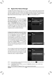
... configure your network settings. If your online game is disabled, you can change the bandwidth. (Note 1) (Note 2) (Note 3) For more instructions on using the Bigfoot Killer Network Manager, click the help icon on the icon in color. It also displays your computer, the Bigfoot Killer Network Manager screen will begin testing (make sure your Internet service provider provides. After installing the LAN driver, you can access...
... configure your network settings. If your online game is disabled, you can change the bandwidth. (Note 1) (Note 2) (Note 3) For more instructions on using the Bigfoot Killer Network Manager, click the help icon on the icon in color. It also displays your computer, the Bigfoot Killer Network Manager screen will begin testing (make sure your Internet service provider provides. After installing the LAN driver, you can access...
Manual
Page 112
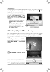
... to Start\All Programs\Creative\Sound Blaster X-Fi and open the MODE SWITCHER. • Audio Creation Mode: Optimizes settings for 3D audio and EAX effects in the Creative Audio Control Panel. Switch to open the Creative Console Launcher (Note 2). To toggle between different modes, click the Mode icon on Windows Vista or later. Users can output the encoded signals via a digital output connector such as sound recording...
... to Start\All Programs\Creative\Sound Blaster X-Fi and open the MODE SWITCHER. • Audio Creation Mode: Optimizes settings for 3D audio and EAX effects in the Creative Audio Control Panel. Switch to open the Creative Console Launcher (Note 2). To toggle between different modes, click the Mode icon on Windows Vista or later. Users can output the encoded signals via a digital output connector such as sound recording...
Manual
Page 115
... for High Definition Audio and select Disable and Uninstall. A: The following Award BIOS beep code descriptions may help you identify possible computer problems. (For reference only.) 1 short: System boots successfully 2 short: CMOS setting error 1 long, 9 short: BIOS ROM error 1 long, 1 short: Memory or motherboard error Continuous long beeps: Graphics card not inserted properly 1 long, 2 short: Monitor or graphics card error Continuous short beeps: Power error 1 long, 3 short: Keyboard error - 115 - For motherboards that have a clearing CMOS jumper, refer to the instructions on...
... for High Definition Audio and select Disable and Uninstall. A: The following Award BIOS beep code descriptions may help you identify possible computer problems. (For reference only.) 1 short: System boots successfully 2 short: CMOS setting error 1 long, 9 short: BIOS ROM error 1 long, 1 short: Memory or motherboard error Continuous long beeps: Graphics card not inserted properly 1 long, 2 short: Monitor or graphics card error Continuous short beeps: Power error 1 long, 3 short: Keyboard error - 115 - For motherboards that have a clearing CMOS jumper, refer to the instructions on...


