
Manual
Page 1
...Storage Technology utility to enable the Intel Smart Response Technology • The Intel Smart Response Technology requires a computer system with an Intel Z68 Chipset-based motherboard and an Intel Core series CPU. • The operating system must be used for your computer and press to the SATA disk. • ... Besides the conventional SATA disk, you back up the hard disk before configuring the Smart Response Technology, all original data on the motherboard you enable RAID mode. English Follow the steps below to make it work as a cache of the hard disk. It is 64 GB.
...Storage Technology utility to enable the Intel Smart Response Technology • The Intel Smart Response Technology requires a computer system with an Intel Z68 Chipset-based motherboard and an Intel Core series CPU. • The operating system must be used for your computer and press to the SATA disk. • ... Besides the conventional SATA disk, you back up the hard disk before configuring the Smart Response Technology, all original data on the motherboard you enable RAID mode. English Follow the steps below to make it work as a cache of the hard disk. It is 64 GB.

Manual
Page 2
... Rapid Storage Technology utility. - 2 - Make sure the Intel Rapid Storage Technology driver version is complete, use the "Xpress Install" function of the motherboard driver disk to install all motherboard drivers, including the Intel Rapid Storage Technology driver. After the installation is 10.5 or above and restarting your system, find the IRST...
... Rapid Storage Technology utility. - 2 - Make sure the Intel Rapid Storage Technology driver version is complete, use the "Xpress Install" function of the motherboard driver disk to install all motherboard drivers, including the Intel Rapid Storage Technology driver. After the installation is 10.5 or above and restarting your system, find the IRST...
Manual
Page 2
Motherboard G1.Sniper 2 Jul. 8, 2011 Motherboard G1.Sniper 2 Jul. 8, 2011
Motherboard G1.Sniper 2 Jul. 8, 2011 Motherboard G1.Sniper 2 Jul. 8, 2011
Manual
Page 3
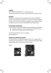
... may be reproduced, copied, translated, transmitted, or published in this product, GIGABYTE provides the following types of documentations: For quick set-up of GIGABYTE. Check your motherboard looks like this manual are legally registered to assist in this : "REV... their respective owners. For product-related information, check on our website at: http://www.gigabyte.com Identifying Your Motherboard Revision The revision number on your motherboard revision before updating motherboard BIOS, drivers, or when looking for technical information. Copyright © 2011 GIGA-BYTE ...
... may be reproduced, copied, translated, transmitted, or published in this product, GIGABYTE provides the following types of documentations: For quick set-up of GIGABYTE. Check your motherboard looks like this manual are legally registered to assist in this : "REV... their respective owners. For product-related information, check on our website at: http://www.gigabyte.com Identifying Your Motherboard Revision The revision number on your motherboard revision before updating motherboard BIOS, drivers, or when looking for technical information. Copyright © 2011 GIGA-BYTE ...
Manual
Page 4
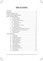
Table of Contents Box Contents...6 Optional Items...6 G1.Sniper 2 Motherboard Layout 7 G1.Sniper 2 Motherboard Block Diagram 8 Chapter 1 Hardware Installation 9 1-1 Installation Precautions 9 1-2 Product Specifications 10 1-3 Installing the CPU and CPU Cooler 13 1-3-1 Installing the CPU 13 1-3-2 Installing the CPU Cooler ...
Table of Contents Box Contents...6 Optional Items...6 G1.Sniper 2 Motherboard Layout 7 G1.Sniper 2 Motherboard Block Diagram 8 Chapter 1 Hardware Installation 9 1-1 Installation Precautions 9 1-2 Product Specifications 10 1-3 Installing the CPU and CPU Cooler 13 1-3-1 Installing the CPU 13 1-3-2 Installing the CPU Cooler ...
Manual
Page 6
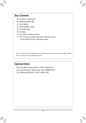
Box Contents G1.Sniper 2 motherboard Motherboard driver disk User's Manual Quick Installation Guide Four SATA cables I/O Shield One 2-Way SLI bridge connector 5.25" Front Access Control Panel with 2 USB 3.0/2.0 ports, 1 Power ...
Box Contents G1.Sniper 2 motherboard Motherboard driver disk User's Manual Quick Installation Guide Four SATA cables I/O Shield One 2-Way SLI bridge connector 5.25" Front Access Control Panel with 2 USB 3.0/2.0 ports, 1 Power ...
Manual
Page 7
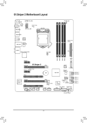
sensor ATX DDR3_4 DDR3_2 DDR3_3 DDR3_1 PCIEX1_1 FAN4 PCIEX16 G1.Sniper 2 System2 Temp. sensor FAN3 F_PANEL OC_BUTTON_F - 7 - sensor ATX_12V_2X4 LGA1155 USB_ESATA R_USB30 Etron EJ168 Marvell USB_LAN 88E1118R AUDIO BigFoot Killer E2100 HP_PWR PHASE LED System4 ... F_USB1 COMA Intel® Z68 Etron EJ168 F_USB30 Marvell 88SE9172 GSATA3_7 GSATA3_6 iTE IT8728 SATA2_4 M_BIOS B_BIOS SATA3_1 SATA3_0 SATA2_3 SATA2_2 CLR_CMOS TPM System3 Temp. G1.Sniper 2 Motherboard Layout KB_MS_USB CPU_FAN OC_BUTTON FAN1 USB_HDMI System1 Temp.
sensor ATX DDR3_4 DDR3_2 DDR3_3 DDR3_1 PCIEX1_1 FAN4 PCIEX16 G1.Sniper 2 System2 Temp. sensor FAN3 F_PANEL OC_BUTTON_F - 7 - sensor ATX_12V_2X4 LGA1155 USB_ESATA R_USB30 Etron EJ168 Marvell USB_LAN 88E1118R AUDIO BigFoot Killer E2100 HP_PWR PHASE LED System4 ... F_USB1 COMA Intel® Z68 Etron EJ168 F_USB30 Marvell 88SE9172 GSATA3_7 GSATA3_6 iTE IT8728 SATA2_4 M_BIOS B_BIOS SATA3_1 SATA3_0 SATA2_3 SATA2_2 CLR_CMOS TPM System3 Temp. G1.Sniper 2 Motherboard Layout KB_MS_USB CPU_FAN OC_BUTTON FAN1 USB_HDMI System1 Temp.
Manual
Page 8
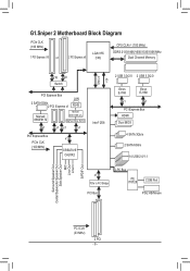
G1.Sniper 2 Motherboard Block Diagram PCIe CLK (100 MHz) 1 PCI Express x16 or 2 PCI Express x8 LGA1155 CPU CPU CLK+/- (100 MHz) DDR3 2133/1866/1600/1333/1066 ...
G1.Sniper 2 Motherboard Block Diagram PCIe CLK (100 MHz) 1 PCI Express x16 or 2 PCI Express x8 LGA1155 CPU CPU CLK+/- (100 MHz) DDR3 2133/1866/1600/1333/1066 ...
Manual
Page 9
...remove the AC power by your hands dry and first touch a metal object to eliminate static electricity. •• Prior to installing the motherboard, please have a problem related to the use of the product, please consult a certified computer technician. - 9 - If you are uncertain...8226; Prior to installation, do not have an ESD wrist strap, keep your dealer. Chapter 1 Hardware Installation 1-1 Installation Precautions The motherboard contains numerous delicate electronic circuits and components which can lead to damage to system components as well as physical harm to the user....
...remove the AC power by your hands dry and first touch a metal object to eliminate static electricity. •• Prior to installing the motherboard, please have a problem related to the use of the product, please consult a certified computer technician. - 9 - If you are uncertain...8226; Prior to installation, do not have an ESD wrist strap, keep your dealer. Chapter 1 Hardware Installation 1-1 Installation Precautions The motherboard contains numerous delicate electronic circuits and components which can lead to damage to system components as well as physical harm to the user....
Manual
Page 12
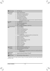
...138;Š Support for Xpress Install ŠŠ Support for Xpress Recovery2 ŠŠ Support for EasyTune * Available functions in EasyTune may differ by motherboard model. ŠŠ Support for Dynamic Energy Saver™ 2 ŠŠ Support for Smart 6™ ŠŠ Support for Auto Green... ŠŠ Support for Microsoft® Windows 7/Vista/XP Form Factor ŠŠ ATX Form Factor; 30.5cm x 26.4cm * GIGABYTE reserves the right to make any changes to the integrated graphics port on the CPU/system cooler you install. I/O Controller ŠŠ iTE ...
...138;Š Support for Xpress Install ŠŠ Support for Xpress Recovery2 ŠŠ Support for EasyTune * Available functions in EasyTune may differ by motherboard model. ŠŠ Support for Dynamic Energy Saver™ 2 ŠŠ Support for Smart 6™ ŠŠ Support for Auto Green... ŠŠ Support for Microsoft® Windows 7/Vista/XP Form Factor ŠŠ ATX Form Factor; 30.5cm x 26.4cm * GIGABYTE reserves the right to make any changes to the integrated graphics port on the CPU/system cooler you install. I/O Controller ŠŠ iTE ...
Manual
Page 13
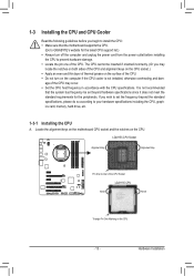
...A. If you may occur. •• Set the CPU host frequency in accordance with the CPU specifications. Locate the alignment keys on the motherboard CPU socket and the notches on the surface of the CPU. Hardware Installation It is not installed, otherwise overheating and dam- The CPU cannot ... support list.) •• Always turn off the computer and unplug the power cord from the power outlet before installing the CPU to GIGABYTE's website for the peripherals. age of the CPU Socket LGA1155 CPU Notch Notch Triangle Pin One Marking on the computer if the CPU cooler...
...A. If you may occur. •• Set the CPU host frequency in accordance with the CPU specifications. Locate the alignment keys on the motherboard CPU socket and the notches on the surface of the CPU. Hardware Installation It is not installed, otherwise overheating and dam- The CPU cannot ... support list.) •• Always turn off the computer and unplug the power cord from the power outlet before installing the CPU to GIGABYTE's website for the peripherals. age of the CPU Socket LGA1155 CPU Notch Notch Triangle Pin One Marking on the computer if the CPU cooler...
Manual
Page 14
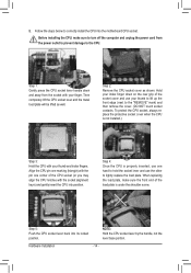
... CPU socket lever and the metal load plate will be lifted as shown. B. Hold your finger. Step 5: Push the CPU socket lever back into the motherboard CPU socket. Step 1: Gently press the CPU socket lever handle down on the rear grip of the load plate is under the shoulder screw. Step...
... CPU socket lever and the metal load plate will be lifted as shown. B. Hold your finger. Step 5: Push the CPU socket lever back into the motherboard CPU socket. Step 1: Gently press the CPU socket lever handle down on the rear grip of the load plate is under the shoulder screw. Step...
Manual
Page 15
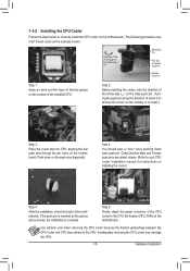
...of the CPU cooler to the CPU fan header (CPU_FAN) on installing the cooler.) Step 5: After the installation, check the back of the motherboard. Hardware Installation Inadequately removing the CPU cooler may adhere to the CPU. If the push pin is inserted as the example cooler.) Direction of...install.) Step 3: Place the cooler atop the CPU, aligning the four push pins through the pin holes on the surface of thermal grease on the motherboard. Step 4: You should hear a "click" when pushing down on the push pins diagonally. Push down each push pin. 1-3-2 Installing the CPU ...
...of the CPU cooler to the CPU fan header (CPU_FAN) on installing the cooler.) Step 5: After the installation, check the back of the motherboard. Hardware Installation Inadequately removing the CPU cooler may adhere to the CPU. If the push pin is inserted as the example cooler.) Direction of...install.) Step 3: Place the cooler atop the CPU, aligning the four push pins through the pin holes on the surface of thermal grease on the motherboard. Step 4: You should hear a "click" when pushing down on the push pins diagonally. Push down each push pin. 1-3-2 Installing the CPU ...
Manual
Page 16
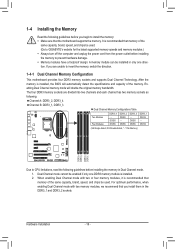
... brand, speed, and chips be used . DS/SS DS/SS DDR3_2 DS/SS - A memory module can be used . (Go to GIGABYTE's website for the latest supported memory speeds and memory modules.) •• Always turn off the computer and unplug the power cord from the...install the memory: •• Make sure that you begin to insert the memory, switch the direction. 1-4-1 Dual Channel Memory Configuration This motherboard provides four DDR3 memory sockets and supports Dual Channel Technology. 1-4 Installing the Memory Read the following guidelines before installing the memory in Dual Channel...
... brand, speed, and chips be used . DS/SS DS/SS DDR3_2 DS/SS - A memory module can be used . (Go to GIGABYTE's website for the latest supported memory speeds and memory modules.) •• Always turn off the computer and unplug the power cord from the...install the memory: •• Make sure that you begin to insert the memory, switch the direction. 1-4-1 Dual Channel Memory Configuration This motherboard provides four DDR3 memory sockets and supports Dual Channel Technology. 1-4 Installing the Memory Read the following guidelines before installing the memory in Dual Channel...
Manual
Page 17
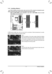
Place the memory module on this motherboard. Hardware Installation Step 2: The clips at both ends of the memory, push down on the memory and insert it can only fit in one direction. ...
Place the memory module on this motherboard. Hardware Installation Step 2: The clips at both ends of the memory, push down on the memory and insert it can only fit in one direction. ...
Manual
Page 18
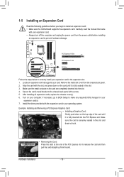
... up from the slot. Remove the metal slot cover from the power outlet before you begin to install an expansion card: • Make sure the motherboard supports the expansion card. Hardware Installation - 18 - Make sure the card is fully inserted into the slot. 444 Secure the card's metal bracket to the...
... up from the slot. Remove the metal slot cover from the power outlet before you begin to install an expansion card: • Make sure the motherboard supports the expansion card. Hardware Installation - 18 - Make sure the card is fully inserted into the slot. 444 Secure the card's metal bracket to the...
Manual
Page 19
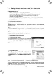
.... - 19 - Procedure and driver screen for enabling CrossFireX/SLI technology may be needed or not depending on top of the two cards. A CrossFireX/SLI-supported motherboard with sufficient power is recommended (Refer to the NVIDIA Control Panel. A power supply with two PCI Express x16 slots and correct driver - Step 3: Plug the...
.... - 19 - Procedure and driver screen for enabling CrossFireX/SLI technology may be needed or not depending on top of the two cards. A CrossFireX/SLI-supported motherboard with sufficient power is recommended (Refer to the NVIDIA Control Panel. A power supply with two PCI Express x16 slots and correct driver - Step 3: Plug the...
Manual
Page 20
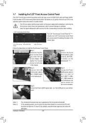
..., press the button again and the button will light red. Step 2: Connect the Quick Boost button's cable to the OC_BUTTON_ F header on the motherboard. (Note 2) Step 3: Step 4: Connect the USB Connect the Power 3.0/2.0 ports' cable to eSATA power cable to hardware. • Insert the... removing the Front Access Control Panel and signal/power cable to prevent damage to the F_USB30 header Pin 1, 3, 5, and 7 of on the motherboard. board. (Note 1) The components received may vary in appearance from the products illustrated. (Note 2) In the operating system, you to the ...
..., press the button again and the button will light red. Step 2: Connect the Quick Boost button's cable to the OC_BUTTON_ F header on the motherboard. (Note 2) Step 3: Step 4: Connect the USB Connect the Power 3.0/2.0 ports' cable to eSATA power cable to hardware. • Insert the... removing the Front Access Control Panel and signal/power cable to prevent damage to the F_USB30 header Pin 1, 3, 5, and 7 of on the motherboard. board. (Note 1) The components received may vary in appearance from the products illustrated. (Note 2) In the operating system, you to the ...
Manual
Page 21
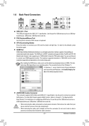
.... 1-8 Back Panel Connectors O.C. USB 2.0/1.1 Port The USB port supports the USB 2.0/1.1 specification. Use this button to overclock your device and then remove it from the motherboard. •• When removing the cable, pull it side to side to a back panel connector, first remove the cable from your CPU and the button...
.... 1-8 Back Panel Connectors O.C. USB 2.0/1.1 Port The USB port supports the USB 2.0/1.1 specification. Use this button to overclock your device and then remove it from the motherboard. •• When removing the cable, pull it side to side to a back panel connector, first remove the cable from your CPU and the button...
Manual
Page 23
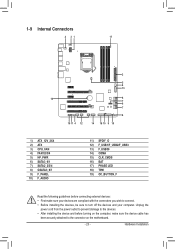
... and your devices are compliant with the connectors you wish to connect. •• Before installing the devices, be sure to the connector on the motherboard. - 23 - Hardware Installation
... and your devices are compliant with the connectors you wish to connect. •• Before installing the devices, be sure to the connector on the motherboard. - 23 - Hardware Installation


