
Service Manual
Page 43
...the left and right when the fixed-format mode is selected) ! OPERATING PRINCIPLES Printer Mechanism 43 Every paper or CD-R tray is loaded, the voltage measured on ...HP detection sequence & CD-R center position detection sequence is less than the detected paper size. (3mm larger at top, 5mm larger at bottom, and 2.5mm lager at the time of the the Paper Guide Front. " CD-R tray (Only for Stylus PHOTO... the following timings and locations and used to detect the roll paper edge. EPSON Stylus PHOTO 2100/2200 2.2.1.3 Sequence Used for PW Detection The PW detector on the CD-R tray,...
...the left and right when the fixed-format mode is selected) ! OPERATING PRINCIPLES Printer Mechanism 43 Every paper or CD-R tray is loaded, the voltage measured on ...HP detection sequence & CD-R center position detection sequence is less than the detected paper size. (3mm larger at top, 5mm larger at bottom, and 2.5mm lager at the time of the the Paper Guide Front. " CD-R tray (Only for Stylus PHOTO... the following timings and locations and used to detect the roll paper edge. EPSON Stylus PHOTO 2100/2200 2.2.1.3 Sequence Used for PW Detection The PW detector on the CD-R tray,...
Service Manual
Page 63
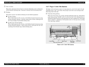
...and displays Cutter position error or Cutter jam error according to 1.27g/color depending on the combination of the cumulative printing timer, cumulative cleaning count and cleaning timer. ! Right HP sensor Left HP sensor Cutter motor Relay board Paper eject roller shaft Paper hold -down... the Periodic flushing timer. A large amount of such main parts as the Cutter motor, left and right HP sensors (2 pcs. Operation during printing When the Cutter blade starts cutting, the Paper hold - EPSON Stylus PHOTO 2100/2200 ! Cutter Mechanism OPERATING PRINCIPLES Printer Mechanism 63
...and displays Cutter position error or Cutter jam error according to 1.27g/color depending on the combination of the cumulative printing timer, cumulative cleaning count and cleaning timer. ! Right HP sensor Left HP sensor Cutter motor Relay board Paper eject roller shaft Paper hold -down... the Periodic flushing timer. A large amount of such main parts as the Cutter motor, left and right HP sensors (2 pcs. Operation during printing When the Cutter blade starts cutting, the Paper hold - EPSON Stylus PHOTO 2100/2200 ! Cutter Mechanism OPERATING PRINCIPLES Printer Mechanism 63

Service Manual
Page 64
... ink, which may stick to the Cutter blade is removed to the HP sensor located in the motion starting position (right HP sensor). EPSON Stylus PHOTO 2100/2200 Revision B 2.2.7.1 Cutter Initialization Sequence When the Cutter is fitted, the cutter initialization sequence is executed if the printer has confirmed that plate, with the leading edge of the fed...
... ink, which may stick to the Cutter blade is removed to the HP sensor located in the motion starting position (right HP sensor). EPSON Stylus PHOTO 2100/2200 Revision B 2.2.7.1 Cutter Initialization Sequence When the Cutter is fitted, the cutter initialization sequence is executed if the printer has confirmed that plate, with the leading edge of the fed...

Service Manual
Page 65
...to the operation in "Without paper/Carriage inside HP" is fixed by the CR lock lever. When there is done to prevent double feed during that was stopping above the Paper separation pad. 2. OPERATING PRINCIPLES Printer Mechanism 65 EPSON Stylus PHOTO 2100/2200 2.2.8 Power-On Sequence The following explains the...eject roller shafts A, B stop soon, and the Carriage is no paper and the Carriage is inside HP (CR locked) 1. Without paper/Carriage inside or outside the HP with the printer powered on , the drive of the CR motor is transmitted to the LD roller shaft through the timing...
...to the operation in "Without paper/Carriage inside HP" is fixed by the CR lock lever. When there is done to prevent double feed during that was stopping above the Paper separation pad. 2. OPERATING PRINCIPLES Printer Mechanism 65 EPSON Stylus PHOTO 2100/2200 2.2.8 Power-On Sequence The following explains the...eject roller shafts A, B stop soon, and the Carriage is no paper and the Carriage is inside HP (CR locked) 1. Without paper/Carriage inside or outside the HP with the printer powered on , the drive of the CR motor is transmitted to the LD roller shaft through the timing...
Service Manual
Page 67
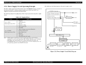
EPSON Stylus PHOTO 2100/2200 2.3.1 Power Supply Circuit Operating Principle The power supply circuit board of the circuit uses the RCC switching regulator method and +42VDC and +5DVC are supplied ... • Panel LED • Nozzle selection circuit (above Printhead) • Interface control circuit • Ink cartridge sensor • PE sensor • ASF sensor • Cutter HP sensors (left, right) Note: +5VDC applies to the printer mechanism and control boards. Revision B Figure 2-18. The following is the C387 PSB/PSE. Table 2-15.
EPSON Stylus PHOTO 2100/2200 2.3.1 Power Supply Circuit Operating Principle The power supply circuit board of the circuit uses the RCC switching regulator method and +42VDC and +5DVC are supplied ... • Panel LED • Nozzle selection circuit (above Printhead) • Interface control circuit • Ink cartridge sensor • PE sensor • ASF sensor • Cutter HP sensors (left, right) Note: +5VDC applies to the printer mechanism and control boards. Revision B Figure 2-18. The following is the C387 PSB/PSE. Table 2-15.


