
Getting Started Guide
Page 7
...Refer to the documentation included with the system to describe changes to troubleshoot the system and install or replace system components. NOTE: Always check for updates on support.dell.com and read and follow the safety instructions and important regulatory information in other documents. • ... are sometimes included with your system on installing the stabilizer feet on the CDs that came with your system or from support.dell.com. • CDs included with your system provide documentation and tools for experienced users or technicians. Warranty information may be included...
...Refer to the documentation included with the system to describe changes to troubleshoot the system and install or replace system components. NOTE: Always check for updates on support.dell.com and read and follow the safety instructions and important regulatory information in other documents. • ... are sometimes included with your system on installing the stabilizer feet on the CDs that came with your system or from support.dell.com. • CDs included with your system provide documentation and tools for experienced users or technicians. Warranty information may be included...

Hardware Owner's Manual (PDF)
Page 5
... Removing the Diskette Drive 72 Installing the Diskette Drive Into the Drive Carrier 74 Installing the Diskette Drive 74 System Battery 75 Replacing the System Battery 75 Cooling Shroud 77 Removing the Cooling Shroud 77 Installing the Cooling Shroud 79 Fan Brackets 79 Removing the... 83 Removing Memory Modules 85 Installing a RAC Card 85 Activating the Integrated NIC TOE 87 Microprocessor 87 Replacing a Processor 88 SAS RAID Controller Daughter Card 92 Replacing the SAS RAID Controller Daughter Card Battery 92 Removing the SAS RAID Controller Daughter Card 93 Installing the ...
... Removing the Diskette Drive 72 Installing the Diskette Drive Into the Drive Carrier 74 Installing the Diskette Drive 74 System Battery 75 Replacing the System Battery 75 Cooling Shroud 77 Removing the Cooling Shroud 77 Installing the Cooling Shroud 79 Fan Brackets 79 Removing the... 83 Removing Memory Modules 85 Installing a RAC Card 85 Activating the Integrated NIC TOE 87 Microprocessor 87 Replacing a Processor 88 SAS RAID Controller Daughter Card 92 Replacing the SAS RAID Controller Daughter Card Battery 92 Removing the SAS RAID Controller Daughter Card 93 Installing the ...
Hardware Owner's Manual (PDF)
Page 17
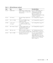
... Problems" on page 131. If the problem persists, see "Getting Help" on page 109. See bad, or unable to recharge due to "Replacing the SAS RAID thermal issues. Processor # VCORE voltage regulator has failed. RPM of specified cooling fan is reporting a system error. Cooling Problems" ...voltage has exceeded the allowable voltage range See "Getting Help" on page 109. See your system's Information Update Tech Sheet located on support.dell.com for the most current system information. LCD Status Messages (continued) Code E1211 E12nn E1229 E122B E122C E1310 E1410 Text ROMB Batt XX ...
... Problems" on page 131. If the problem persists, see "Getting Help" on page 109. See bad, or unable to recharge due to "Replacing the SAS RAID thermal issues. Processor # VCORE voltage regulator has failed. RPM of specified cooling fan is reporting a system error. Cooling Problems" ...voltage has exceeded the allowable voltage range See "Getting Help" on page 109. See your system's Information Update Tech Sheet located on support.dell.com for the most current system information. LCD Status Messages (continued) Code E1211 E12nn E1229 E122B E122C E1310 E1410 Text ROMB Batt XX ...
Hardware Owner's Manual (PDF)
Page 22
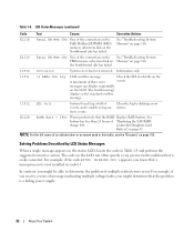
.... Solving Problems Described by deleting event entries. messages can often specify a very precise fault condition that the RAID Replace RAID battery. The code on page 110. E2119 Fatal SB Mem CRC One of "Replacing the SAS RAID charge left. I1910 Intrusion System cover has been removed. For example, if the code E0780...
.... Solving Problems Described by deleting event entries. messages can often specify a very precise fault condition that the RAID Replace RAID battery. The code on page 110. E2119 Fatal SB Mem CRC One of "Replacing the SAS RAID charge left. I1910 Intrusion System cover has been removed. For example, if the code E0780...
Hardware Owner's Manual (PDF)
Page 25
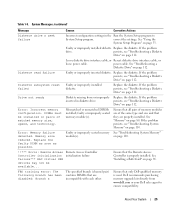
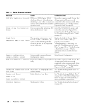
...page 112. Error: Incorrect memory configuration. Remote Access Controller initialization failure Ensure that only Dell-qualified memory is properly installed. Table 1-5. Faulty or improperly installed diskette Replace the diskette. See "Troubleshooting a Diskette Drive" on page 112. Diskette read failure... and technology. Faulty or improperly seated memory See "Troubleshooting System Memory" module(s). Replace the diskette. Drive not ready Diskette missing from www.dell.com or your Dell sales agent to System Setup program. See "Using the System Setup Program" on ...
...page 112. Error: Incorrect memory configuration. Remote Access Controller initialization failure Ensure that only Dell-qualified memory is properly installed. Table 1-5. Faulty or improperly installed diskette Replace the diskette. See "Troubleshooting a Diskette Drive" on page 112. Diskette read failure... and technology. Faulty or improperly seated memory See "Troubleshooting System Memory" module(s). Replace the diskette. Drive not ready Diskette missing from www.dell.com or your Dell sales agent to System Setup program. See "Using the System Setup Program" on ...
Hardware Owner's Manual (PDF)
Page 28
... Memory" on page 117. Ensure that the diskette and hard drive cables are securely shadowing. faulty or improperly installed problem persists, see "Troubleshooting expansion card. Replace the diskette. Ensure that faulty. Read fault The operating system cannot read Requested sector not found from the diskette or hard drive, the system could...
... Memory" on page 117. Ensure that the diskette and hard drive cables are securely shadowing. faulty or improperly installed problem persists, see "Troubleshooting expansion card. Replace the diskette. Ensure that faulty. Read fault The operating system cannot read Requested sector not found from the diskette or hard drive, the system could...
Hardware Owner's Manual (PDF)
Page 29
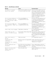
...are not compatible: DIMM x and incompatible with the system. Dell recommends purchasing memory upgrade kits directly from www.dell.com or your Dell sales agent to determine if single-bit or multi-bit errors were detected and replace the faulty memory module. The following DIMMs are The specified... DIMM(s) are incompatible with your Dell sales agent to ensure compatibility. Ensure that came with the system. See "System Battery"...
...are not compatible: DIMM x and incompatible with the system. Dell recommends purchasing memory upgrade kits directly from www.dell.com or your Dell sales agent to determine if single-bit or multi-bit errors were detected and replace the faulty memory module. The following DIMMs are The specified... DIMM(s) are incompatible with your Dell sales agent to ensure compatibility. Ensure that came with the system. See "System Battery"...

Hardware Owner's Manual (PDF)
Page 48
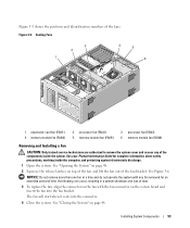
... lays flat on top of the system. CAUTION: Whenever you need to lift the system, get others to the locked position. See Figure 3-3. 5 If applicable, replace the Kensington cable lock on the back of the system chassis. 4 To remove the system cover, turn the latch release lock on the back of...
... lays flat on top of the system. CAUTION: Whenever you need to lift the system, get others to the locked position. See Figure 3-3. 5 If applicable, replace the Kensington cable lock on the back of the system chassis. 4 To remove the system cover, turn the latch release lock on the back of...
Hardware Owner's Manual (PDF)
Page 52
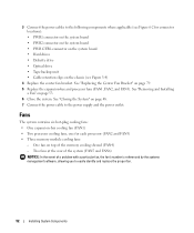
... Center Fan Bracket" on page 53. 6 Close the system. See "Removing and Installing a Fan" on page 79. 5 Replace the expansion-bay and processor fans (FAN1, FAN2, and FAN3). Two fans at the rear of the system (FAN5 and FAN6) NOTICE: In the event ... Figure 6-2 for each processor (FAN2 and FAN3) • Three memory module cooling fans: - 3 Connect the power cables to the following components where applicable (see Figure 3-4) 4 Replace the center fan bracket. One fan on top of a problem with a particular fan, the fan's number is referenced by the systems management software, allowing you...
... Center Fan Bracket" on page 53. 6 Close the system. See "Removing and Installing a Fan" on page 79. 5 Replace the expansion-bay and processor fans (FAN1, FAN2, and FAN3). Two fans at the rear of the system (FAN5 and FAN6) NOTICE: In the event ... Figure 6-2 for each processor (FAN2 and FAN3) • Three memory module cooling fans: - 3 Connect the power cables to the following components where applicable (see Figure 3-4) 4 Replace the center fan bracket. One fan on top of a problem with a particular fan, the fan's number is referenced by the systems management software, allowing you...
Hardware Owner's Manual (PDF)
Page 53
... Product Information Guide for an extended period of the fan bracket. See Figure 3-6. Overheating can occur, resulting in a system shutdown and loss of data. 3 To replace the fan, align the connector on the system board and insert the fan into the connector. 4 Close the system. Installing System Components 53 Cooling Fans...
... Product Information Guide for an extended period of the fan bracket. See Figure 3-6. Overheating can occur, resulting in a system shutdown and loss of data. 3 To replace the fan, align the connector on the system board and insert the fan into the connector. 4 Close the system. Installing System Components 53 Cooling Fans...
Hardware Owner's Manual (PDF)
Page 55
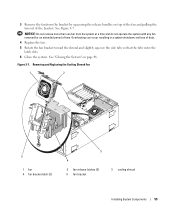
...one fan from the bracket by squeezing the release handles on page 48. Overheating can occur resulting in a system shutdown and loss of data. 4 Replace the fan. 5 Rotate the fan bracket toward the shroud and slightly squeeze the side tabs so that the tabs enter the latch slots. 6 ...Close the system. See "Closing the System" on top of the fan and pulling the fan out of time. Figure 3-7. Removing and Replacing the Cooling Shroud Fan 1 2 5 1 fan 4 fan bracket latch (2) 3 4 2 fan release latches (2) 5 fan bracket 3 cooling shroud Installing System Components 55 See...
...one fan from the bracket by squeezing the release handles on page 48. Overheating can occur resulting in a system shutdown and loss of data. 4 Replace the fan. 5 Rotate the fan bracket toward the shroud and slightly squeeze the side tabs so that the tabs enter the latch slots. 6 ...Close the system. See "Closing the System" on top of the fan and pulling the fan out of time. Figure 3-7. Removing and Replacing the Cooling Shroud Fan 1 2 5 1 fan 4 fan bracket latch (2) 3 4 2 fan release latches (2) 5 fan bracket 3 cooling shroud Installing System Components 55 See...
Hardware Owner's Manual (PDF)
Page 58
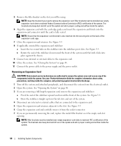
.... Filler brackets must be installed over the empty card-slot opening. Removing an Expansion Card CAUTION: Only trained service technicians are permanently removing the card, replace the metal filler bracket over empty expansion-card slots to remove the system cover and access any internal or external cables that the expansion-card...
.... Filler brackets must be installed over the empty card-slot opening. Removing an Expansion Card CAUTION: Only trained service technicians are permanently removing the card, replace the metal filler bracket over empty expansion-card slots to remove the system cover and access any internal or external cables that the expansion-card...
Hardware Owner's Manual (PDF)
Page 66
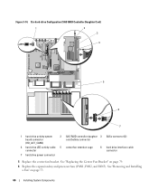
... expansion-bay and processor fans (FAN1, FAN2, and FAN3). See "Replacing the Center Fan Bracket" on page 53. 66 Installing System Components Six-hard-drive Configuration (SAS RAID Controller Daughter Card) 1 2 3 4 5 6 7 1 hard drive activity system board ... daughter 3 SASx connector (2) card battery connector 4 hard drive LED activity cable 5 center fan retention cage connector 6 hard drive interface cable connector 7 hard drive power connector 5 Replace the center fan bracket. Figure 3-14.
... expansion-bay and processor fans (FAN1, FAN2, and FAN3). See "Replacing the Center Fan Bracket" on page 53. 66 Installing System Components Six-hard-drive Configuration (SAS RAID Controller Daughter Card) 1 2 3 4 5 6 7 1 hard drive activity system board ... daughter 3 SASx connector (2) card battery connector 4 hard drive LED activity cable 5 center fan retention cage connector 6 hard drive interface cable connector 7 hard drive power connector 5 Replace the center fan bracket. Figure 3-14.
Hardware Owner's Manual (PDF)
Page 67
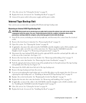
... pull the cable out of the way of the components inside the system. See "Removing and Installing a Fan" on page 68. 12 Replace the center fan bracket. Internal Tape Backup Unit Your system can accommodate an optional SCSI internal tape backup unit. Removing an Internal SCSI Tape ...are authorized to the power supply and the power outlet. See "Closing the System" on page 47. See "Installing the Bezel" on page 48. 8 Replace the bezel, if removed. Installing System Components 67 7 Close the system. See "Installing the Bezel" on page 53. 7 Remove the center fan bracket. ...
... pull the cable out of the way of the components inside the system. See "Removing and Installing a Fan" on page 68. 12 Replace the center fan bracket. Internal Tape Backup Unit Your system can accommodate an optional SCSI internal tape backup unit. Removing an Internal SCSI Tape ...are authorized to the power supply and the power outlet. See "Closing the System" on page 47. See "Installing the Bezel" on page 48. 8 Replace the bezel, if removed. Installing System Components 67 7 Close the system. See "Installing the Bezel" on page 53. 7 Remove the center fan bracket. ...
Hardware Owner's Manual (PDF)
Page 69
... the tape drive's termination if it is no requirement that SCSI ID numbers be assigned sequentially or that devices be unterminated. See Figure 3-15. 13 Replace the center fan bracket. See "Installing the SAS RAID Controller Daughter Card" on page 53. 6 Remove the center fan bracket. See "Removing and ...be attached to the SAS RAID controller daughter card or expansion card. NOTE: There is the last device in order by ID number. See "Replacing the Center Fan Bracket" on page 79. 14 Connect the SCSI interface cable to the SCSI connector on . See "Removing the SAS RAID Controller...
... the tape drive's termination if it is no requirement that SCSI ID numbers be assigned sequentially or that devices be unterminated. See Figure 3-15. 13 Replace the center fan bracket. See "Installing the SAS RAID Controller Daughter Card" on page 53. 6 Remove the center fan bracket. See "Removing and ...be attached to the SAS RAID controller daughter card or expansion card. NOTE: There is the last device in order by ID number. See "Replacing the Center Fan Bracket" on page 79. 14 Connect the SCSI interface cable to the SCSI connector on . See "Removing the SAS RAID Controller...
Hardware Owner's Manual (PDF)
Page 70
...attached. See "Removing and Installing a Fan" on page 46. 3 Open the system. See "Closing the System" on page 79. 13 Replace the fans into the center fan bracket. See your Product Information Guide for complete information about safety precautions, working inside the computer, and protecting ...Turn off the system, including any of the peripheral bay to their electrical outlets. 70 Installing System Components See "Replacing the Center Fan Bracket" on page 48. 16 Replace the front bezel, if removed. See "Installing the Bezel" on page 48. 4 If applicable, disconnect the cables...
...attached. See "Removing and Installing a Fan" on page 46. 3 Open the system. See "Closing the System" on page 79. 13 Replace the fans into the center fan bracket. See your Product Information Guide for complete information about safety precautions, working inside the computer, and protecting ...Turn off the system, including any of the peripheral bay to their electrical outlets. 70 Installing System Components See "Replacing the Center Fan Bracket" on page 48. 16 Replace the front bezel, if removed. See "Installing the Bezel" on page 48. 4 If applicable, disconnect the cables...
Hardware Owner's Manual (PDF)
Page 71
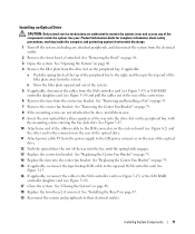
..., and protecting against electrostatic discharge. 1 Turn off the system, including any of the way into the bay until the spring latch engages. 13 Replace the center fan bracket. Installing an Optical Drive CAUTION: Only trained service technicians are not attached to the drive, install them now. 9 Insert ...about safety precautions, working inside the system. b Draw the filler plate upward and out of the way into the center fan bracket. See "Replacing the Center Fan Bracket" on page 79. 15 If applicable, reconnect the tape backup SCSI cable to the optional SCSI controller card. See "...
..., and protecting against electrostatic discharge. 1 Turn off the system, including any of the way into the bay until the spring latch engages. 13 Replace the center fan bracket. Installing an Optical Drive CAUTION: Only trained service technicians are not attached to the drive, install them now. 9 Insert ...about safety precautions, working inside the system. b Draw the filler plate upward and out of the way into the center fan bracket. See "Replacing the Center Fan Bracket" on page 79. 15 If applicable, reconnect the tape backup SCSI cable to the optional SCSI controller card. See "...
Hardware Owner's Manual (PDF)
Page 75
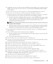
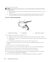
... peripherals, and disconnect the system from the power supply to the power connector on the rear of the diskette drive. 9 If applicable, replace the components your Product Information Guide for the location of the system battery and then, starting with PCI slot 6, remove as many expansion ...cards as you need to create enough room in step 4: a Replace the center fan bracket. See "Installing the Bezel" on page 53 c If applicable, reconnect the cables to their electrical outlets. See "Removing and ...
... peripherals, and disconnect the system from the power supply to the power connector on the rear of the diskette drive. 9 If applicable, replace the components your Product Information Guide for the location of the system battery and then, starting with PCI slot 6, remove as many expansion ...cards as you need to create enough room in step 4: a Replace the center fan bracket. See "Installing the Bezel" on page 53 c If applicable, reconnect the cables to their electrical outlets. See "Removing and ...
Hardware Owner's Manual (PDF)
Page 76
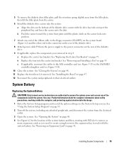
...Setup program to confirm that the battery operates properly. 11 From the main screen, select System Time to the battery connector, you removed in step 4. Replacing the System Battery 1 2 3 1 positive side of connector 2 system battery 3 negative side of connector 6 Install the new system battery (see "...up out of the securing tabs at the positive side of the connector and pry it up , and slide it snaps into place. 7 Replace all the expansion cards you must firmly support the connector while installing or removing a battery. Figure 3-18. a Support the battery connector by...
...Setup program to confirm that the battery operates properly. 11 From the main screen, select System Time to the battery connector, you removed in step 4. Replacing the System Battery 1 2 3 1 positive side of connector 2 system battery 3 negative side of connector 6 Install the new system battery (see "...up out of the securing tabs at the positive side of the connector and pry it up , and slide it snaps into place. 7 Replace all the expansion cards you must firmly support the connector while installing or removing a battery. Figure 3-18. a Support the battery connector by...

Hardware Owner's Manual (PDF)
Page 79
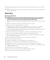
...the latches. If the bracket does not disengage completely, push down slightly on page 93. 4 Remove the fans from the center fan bracket. Replacing the Center Fan Bracket 1 Align the rails on each end of the center fan bracket. See your Product Information Guide for complete information about safety... fan bracket with the tracks on the right chassis wall and then slowly lower the shroud straight down into the system until the latches engage. 2 Replace the fans into place. See "Opening the System" on page 48. 3 If applicable, disconnect the cables from the electrical outlet. 2 Open the ...
...the latches. If the bracket does not disengage completely, push down slightly on page 93. 4 Remove the fans from the center fan bracket. Replacing the Center Fan Bracket 1 Align the rails on each end of the center fan bracket. See your Product Information Guide for complete information about safety... fan bracket with the tracks on the right chassis wall and then slowly lower the shroud straight down into the system until the latches engage. 2 Replace the fans into place. See "Opening the System" on page 48. 3 If applicable, disconnect the cables from the electrical outlet. 2 Open the ...


