
Dell PowerEdge 1900 Support Question
Dell PowerEdge 1900 Support Question
Find answers below for this question about Dell PowerEdge 1900.Need a Dell PowerEdge 1900 manual? We have 7 online manuals for this item!
Question posted by lapyasm on June 8th, 2014
How To Replace Dell Poweredge 1900 Power Supply
The person who posted this question about this Dell product did not include a detailed explanation. Please use the "Request More Information" button to the right if more details would help you to answer this question.
Current Answers
Answer #1: Posted by TechSupport101 on June 8th, 2014 7:43 AM
TechSupport101

Member since:
May 24th, 2013 Points: 12,171,305

Member since:
May 24th, 2013 Points: 12,171,305
Hi. See "Installing the Power Supply" on page 51 of the 'Hardware Owner's Manual here http://www.helpowl.com/manuals/Dell/PowerEdge1900/106829
Related Dell PowerEdge 1900 Manual Pages
Getting Started Guide - Page 5

... performance by installing a second processor, you must order the processor upgrade kits from Dell contains the correct version of the processor and heat sink.
• A minimum ... management software if the top cover is opened.
• An 800-W power supply.
• Six system cooling fans. The upgrade kit from Dell.
The system board includes the following features:
• Six PCI slots ...
Hardware Owner's Manual (PDF) - Page 18
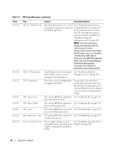
...in an
Microprocessors" on page 109.
processor initialization error. supply is
cleared using either Server
Assistant or the BMC Management
Utility. LCD Status Messages (... See "Getting Help" on page 118.
Power supply voltage is out of See "Troubleshooting the Power acceptable range;
See the Dell OpenManage
Baseboard Management
Controller User's Guide for
information...
Hardware Owner's Manual (PDF) - Page 22
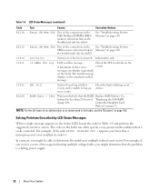
...Replace RAID battery.
W1228
ROMB Batt < 24hr
Warns predictively that is not installed in socket 1. The code on the LCD can display sequentially
on the Northbound side has failed.
Controller Daughter Card
Battery" on page 110.
For example, if you receive a series of events, and is a failing power supply..." on the
A maximum of "Replacing the SAS RAID
charge left.
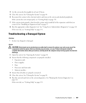
Hardware Owner's Manual (PDF) - Page 52
See "Removing and Installing
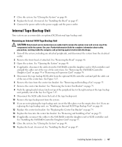
a Fan" on page 48. 7 Connect the power cable to the power supply and the power outlet. Two fans at the rear of the system (FAN5 and FAN6) ... drive • Optical drive • Tape backup unit • Cable retention clips on page 79. 5 Replace the expansion-bay and processor fans (FAN1, FAN2, and FAN3). See "Closing the System" on page 53. 6 Close the ...
Hardware Owner's Manual (PDF) - Page 58
NOTE: Keep this bracket if you need to the power supply and the power outlet. The brackets also keep dust and dirt out of the system and aid in proper cooling and ...opening. b Draw the stabilizer straight up from the socket connector. 7 If you are permanently removing the card, replace the metal filler bracket over empty expansion-card slots to the expansion card. 10 Close the system.
Hardware Owner's Manual (PDF) - Page 67
... fans from the system. 11 If you are authorized to the power supply and the power outlet. See Figure 3-15. 9 Disconnect the SCSI cable from the back of the center fans. See "Replacing the Center Fan Bracket" on page 47. 9 Connect the power cable to remove the system cover and access any of the components...
Hardware Owner's Manual (PDF) - Page 71
...power cable P5 from the power supply to the CD power connect or on the system board (see Figure 3-14) and pull the cables out of the way of the way into the center fan bracket. See "Replacing... the system cover and access any attached peripherals, and disconnect the system from the system. See "Replacing the Center Fan Bracket" on page 53. 7 Remove the center fan bracket. See "Removing and...
Hardware Owner's Manual (PDF) - Page 75
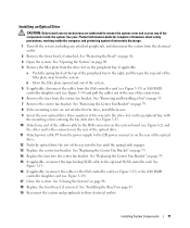
... technicians are authorized to remove the system cover and access any attached peripherals, and disconnect the system from the power supply to the power connector on the rear of the diskette drive.
9 If applicable, replace the components your Product Information Guide for the location of the peripheral bay and lower the carrier unto the...
Hardware Owner's Manual (PDF) - Page 85
... operate your Product Information Guide for some time after the system has been powered down the system. See Figure 6-2. Handle the DIMMs by the card edges...Replace the memory cooling shroud.
See "Opening the System" on each end of the socket until the memory module pops out of this procedure, checking to ensure that the memory modules are authorized to the power supply and the power...
Hardware Owner's Manual (PDF) - Page 107
... 2 Ensure that the following components are properly installed:
• Expansion cards • Power supplies • Fans • Processors and heat sinks • Memory modules 3 Ensure that ...CAUTION: Only trained service technicians are properly connected. 4 Close the system. See "Using Server Administrator Diagnostics" on page 57. 8 Run the appropriate online diagnostic test. See "...
Hardware Owner's Manual (PDF) - Page 108
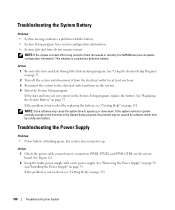
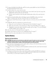
.... If the problem is caused by replacing the battery, see "Getting Help" on the system board. Action 1 Check the power cable connections to operate normally except for weeks or months), the NVRAM may be caused by software rather than by a defective battery. Troubleshooting the Power Supply
Problem • Power button is turned off the system...
Hardware Owner's Manual (PDF) - Page 161
... file also usually includes sections that automatically supplies power to determine a variety of colors. Windows Powered -
UNIX - A battery-powered unit that contain optional settings for multiple ...running. video driver - Universal Serial Bus. Unshielded twisted pair. WH -
Windows Server 2003 - Improves data-transfer performance over IP networks by the number of Microsoft software...
Hardware Owner's Manual (PDF) - Page 165
... disabling, 129 setup, 43 system, 41
PCIe/PCI-X expansion slots, 56
peripheral bay optical drive, 70 tape backup unit, 68
POST accessing system features, 10
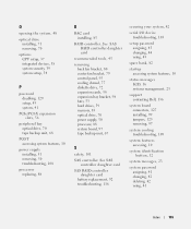
power supply installing, 51 removing, 50 troubleshooting, 108
processor replacing, 88
R
RAC card installing, 85
RAID controller.
Information Update - Page 1
Dell™ PowerEdge™ 1900 Systems
Information Update
www.dell.com | support.dell.com
Installing a SATA Optical Drive - Page 3

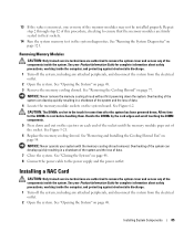
... "Opening the System" in your Hardware Owner's Manual.
5 Disconnect the data and power cables from the electrical outlet.
2 Remove the bezel. b Remove the center fans and the center fan bracket. Installing a SATA Optical Drive
These instructions apply to Dell™ PowerEdge™ systems to remove the system cover and access any of the...
Installing a SATA Optical Drive - Page 4
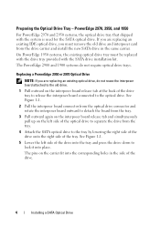
The PowerEdge 2900 and 1900 systems do not reuse the interposer board attached to the optical drive. Replacing a PowerEdge 2950 or 2970 Optical Drive
NOTE: If you must be replaced with the drive tray provided with the system is used for the SATA optical drive. PowerEdge 2970, 2950, and 1950
For PowerEdge 2970 and 2950 systems, the optical...
Installing a SATA Optical Drive - Page 5

... or 2970 System
2 1
3
4
5
6
7
1 optical drive 3 interposer 5 SATA power cable 7 optical drive carrier
2 interposer release latch 4 SATA cable 6 carrier latch
Replacing a PowerEdge 1950 Optical Drive
NOTE: The replacement drive tray provided in the side of the SATA optical drive into the tray until the pins on the carrier align with the holes in ...
Installing a SATA Optical Drive - Page 6

... to the SATA_A connector on top of the optical drive.
3 Connect the branching power cable to the back of the chipset shroud. NOTE: You may need to replace the existing power cable with the branching power cable) to the power supply connector. PowerEdge 1950
1 Insert the optical drive tray into the system until it is fully inserted...
Installing a SATA Optical Drive - Page 7

... your Hardware Owner's Manual.
6 Close the system. Installing a SATA Optical Drive
7 SATA Cable Routing in your Hardware Owner's Manual.
7 Reconnect the system to the power supply connector.
PowerEdge 2970 or 2950
1 Insert the optical drive tray into the system until it is fully inserted and locked into position.
2 Connect the SATA cable (the...
Installing a SATA Optical Drive - Page 9

... to the system board over the top of the fan bracket and connect the cable to the power supply as follows:
- For a PowerEdge 1900, use the SATA_B connector.
- See "Replacing the Center Fan Bracket" in your Hardware Owner's Manual.
6 Replace the fans in the optical drive kit and connect one end to the optical drive and...
Similar Questions

Power Supply Nd444
Hi, i need the electronic schematic of ND 444 power supply. Can someone help me? Thanks. Renato....
Hi, i need the electronic schematic of ND 444 power supply. Can someone help me? Thanks. Renato....
(Posted by bragionr 9 years ago)


How Can I Turn On The Poweredge 6850 Power Supply Alone, Without Any Server?
(Posted by rocketclemens 12 years ago)