
Getting Started Guide
Page 6
... about booting from an external device attached to a SAS or SCSI adapter, including SAS 5/E, PERC 5/E, or PERC 4e/DC. This video subsystem contains 16 MB of supporting a diskette drive, a CD-ROM or DVD-ROM drive, a keyboard, a mouse, or a USB flash drive. • Optional remote access controller (RAC) for the latest support information about specific features, see "Technical Specifications" on the back) capable of DDR SDRAM video memory (nonupgradable). When the optional RAC is installed, the video resolution...
... about booting from an external device attached to a SAS or SCSI adapter, including SAS 5/E, PERC 5/E, or PERC 4e/DC. This video subsystem contains 16 MB of supporting a diskette drive, a CD-ROM or DVD-ROM drive, a keyboard, a mouse, or a USB flash drive. • Optional remote access controller (RAC) for the latest support information about specific features, see "Technical Specifications" on the back) capable of DDR SDRAM video memory (nonupgradable). When the optional RAC is installed, the video resolution...
Hardware Owner's Manual (PDF)
Page 4
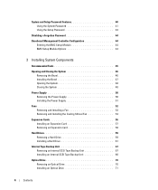
... Disabling a Forgotten Password 44 Baseboard Management Controller Configuration 44 Entering the BMC Setup Module 44 BMC Setup Module Options 44 3 Installing System Components Recommended Tools 45 Opening and Closing the System 46 Removing the Bezel 46 Installing the Bezel 47 Opening the System 48 Closing the System 48 Power Supply 50 Removing the Power Supply 50 Installing the Power Supply 51 Fans 52 Removing and Installing a Fan 53 Removing and Installing the Cooling Shroud Fan 54 Expansion Cards 56 Installing an Expansion Card 57 Removing an Expansion Card 58 Hard Drives...
... Disabling a Forgotten Password 44 Baseboard Management Controller Configuration 44 Entering the BMC Setup Module 44 BMC Setup Module Options 44 3 Installing System Components Recommended Tools 45 Opening and Closing the System 46 Removing the Bezel 46 Installing the Bezel 47 Opening the System 48 Closing the System 48 Power Supply 50 Removing the Power Supply 50 Installing the Power Supply 51 Fans 52 Removing and Installing a Fan 53 Removing and Installing the Cooling Shroud Fan 54 Expansion Cards 56 Installing an Expansion Card 57 Removing an Expansion Card 58 Hard Drives...
Hardware Owner's Manual (PDF)
Page 10
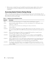
... 1-1. Enters the SAS Configuration Utility. Enters the RAID configuration utility, which allows access to selected DRAC configuration settings. See the DRAC user's guide for more information, see "Integrated Devices Screen" on setup and use of DRAC. 10 About Your System For more information on page 38). If your RAID card. Option is displayed only if you to the system or documentation or advanced technical reference material intended for PXE boot. This...
... 1-1. Enters the SAS Configuration Utility. Enters the RAID configuration utility, which allows access to selected DRAC configuration settings. See the DRAC user's guide for more information, see "Integrated Devices Screen" on setup and use of DRAC. 10 About Your System For more information on page 38). If your RAID card. Option is displayed only if you to the system or documentation or advanced technical reference material intended for PXE boot. This...
Hardware Owner's Manual (PDF)
Page 19
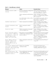
... problem persists, see "Troubleshooting the Power Supply" on a component that resides in PCI configuration space at bus ##, device ##, function ##. See "Getting Help" on a component expansion cards. PCIE Fatal Err B## D## F## PCIE Fatal Err Slot # The system BIOS has reported a PCIe fatal error on page 108. If problem persists, see "Troubleshooting Expansion Cards" on page 117. Remove and reseat the PCI expansion cards. If the problem persists, the The system BIOS has reported a system board is faulty. LCD Status Messages (continued) Code...
... problem persists, see "Troubleshooting the Power Supply" on a component that resides in PCI configuration space at bus ##, device ##, function ##. See "Getting Help" on a component expansion cards. PCIE Fatal Err B## D## F## PCIE Fatal Err Slot # The system BIOS has reported a PCIe fatal error on page 108. If problem persists, see "Troubleshooting Expansion Cards" on page 117. Remove and reseat the PCI expansion cards. If the problem persists, the The system BIOS has reported a system board is faulty. LCD Status Messages (continued) Code...
Hardware Owner's Manual (PDF)
Page 25
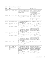
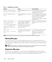
... been disabled: Branch x The specified branch (channel pair) contains DIMMs that all pairs of memory modules are of matched memory size, speed, and technology. If the problem drive. Error: Incorrect memory configuration. Mismatched or unmatched DIMMs installed; Error: Memory failure detected. Memory size reduced. power cable. Diskette subsystem reset failed Faulty or improperly installed diskette. Replace the diskette. faulty or improperly seated memory module(s). If the problem persists, see "Troubleshooting a Diskette Drive" on page 33. Dell recommends purchasing...
... been disabled: Branch x The specified branch (channel pair) contains DIMMs that all pairs of memory modules are of matched memory size, speed, and technology. If the problem drive. Error: Incorrect memory configuration. Mismatched or unmatched DIMMs installed; Error: Memory failure detected. Memory size reduced. power cable. Diskette subsystem reset failed Faulty or improperly installed diskette. Replace the diskette. faulty or improperly seated memory module(s). If the problem persists, see "Troubleshooting a Diskette Drive" on page 33. Dell recommends purchasing...
Hardware Owner's Manual (PDF)
Page 30
.... Diagnostic error messages are generated by typing y (yes) or n (no). System has detected a legal but will warn you that you may result. The system will run system diagnostics, an error message may lose all memory accessible but nonoptimal population of 2, 4, or 8 DIMMs. DIMMs should be populated sequentially starting in "Getting Help" on page 80. Table 1-5. Dell recommends a population of DIMMs (for information about installing or updating the RAID firmware. Warning: The current memory configuration...
.... Diagnostic error messages are generated by typing y (yes) or n (no). System has detected a legal but will warn you that you may result. The system will run system diagnostics, an error message may lose all memory accessible but nonoptimal population of 2, 4, or 8 DIMMs. DIMMs should be populated sequentially starting in "Getting Help" on page 80. Table 1-5. Dell recommends a population of DIMMs (for information about installing or updating the RAID firmware. Warning: The current memory configuration...
Hardware Owner's Manual (PDF)
Page 36
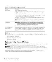
... all error messages relating to the keyboard or keyboard controller during the POST. Hard-Disk Drive Sequence Specifies the order in which the system searches for the latest support information about booting from an external device attached to configure serial communication, external serial connector, failsafe baud rate, remote terminal type, and redirection after boot. PCI IRQ Assignment Displays a screen to change the IRQ assigned to 84-key keyboards). Embedded Server Management Displays a screen to configure...
... all error messages relating to the keyboard or keyboard controller during the POST. Hard-Disk Drive Sequence Specifies the order in which the system searches for the latest support information about booting from an external device attached to configure serial communication, external serial connector, failsafe baud rate, remote terminal type, and redirection after boot. PCI IRQ Assignment Displays a screen to change the IRQ assigned to 84-key keyboards). Embedded Server Management Displays a screen to configure...
Hardware Owner's Manual (PDF)
Page 38
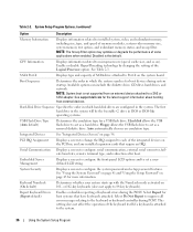
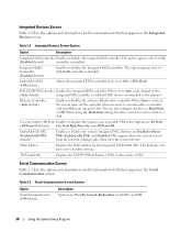
.... 38 Using the System Setup Program TOE Capability Displays the TCP/IP Offload Engine (TOE) feature status of the (Auto default) integrated IDE controller is selected, the system turns off the controller when necessary to boot from the network. When using the Read-Only setting, the drive cannot be set to the channel. PXE support allows the system to accommodate a controller card installed in an expansion slot. Serial Communication Screen Table 2-5 lists the...
.... 38 Using the System Setup Program TOE Capability Displays the TCP/IP Offload Engine (TOE) feature status of the (Auto default) integrated IDE controller is selected, the system turns off the controller when necessary to boot from the network. When using the Read-Only setting, the drive cannot be set to the channel. PXE support allows the system to accommodate a controller card installed in an expansion slot. Serial Communication Screen Table 2-5 lists the...
Hardware Owner's Manual (PDF)
Page 40
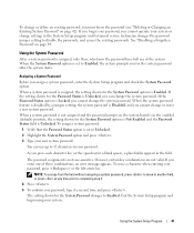
Pressing this button halts the operating system and displays a diagnostic screen. If your data requires more security, use additional forms of security for the data on your system only with system password protection. 40 Using the System Setup Program When disabled, the button can disable the password by changing a jumper setting. On turns on the system by the operating system's documentation. Your system is pressed. Determines how the system reacts when power is...
Pressing this button halts the operating system and displays a diagnostic screen. If your data requires more security, use additional forms of security for the data on your system only with system password protection. 40 Using the System Setup Program When disabled, the button can disable the password by changing a jumper setting. On turns on the system by the operating system's documentation. Your system is pressed. Determines how the system reacts when power is...
Hardware Owner's Manual (PDF)
Page 41
... the Password Status is Unlocked, you press each character key (or the spacebar for the System Password option is assigned, the setting shown for a blank space), a placeholder appears in the System Setup program until a trained service technician changes the password jumper setting to disable the passwords, and erases the existing passwords. When a system password is not case-sensitive. As you can use of these combinations, an error message...
... the Password Status is Unlocked, you press each character key (or the spacebar for the System Password option is assigned, the setting shown for a blank space), a placeholder appears in the System Setup program until a trained service technician changes the password jumper setting to disable the passwords, and erases the existing passwords. When a system password is not case-sensitive. As you can use of these combinations, an error message...
Hardware Owner's Manual (PDF)
Page 106
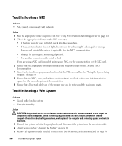
... any of the proper type and do not exceed the maximum length. See "Opening the System" on the NIC connector. • If the link indicator does not light, check all expansion cards installed in the system. See "Using Server Administrator Diagnostics" on page 121. 2 Check the appropriate indicator on page 48. 3 Remove all cable connections. • If the activity indicator does not light, the network driver files might be damaged...
... any of the proper type and do not exceed the maximum length. See "Opening the System" on the NIC connector. • If the link indicator does not light, check all expansion cards installed in the system. See "Using Server Administrator Diagnostics" on page 121. 2 Check the appropriate indicator on page 48. 3 Remove all cable connections. • If the activity indicator does not light, the network driver files might be damaged...
Hardware Owner's Manual (PDF)
Page 109
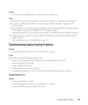
... not blinking green and the system does not power up. If the problem persists, remove the faulty power supply. See "Removing the Power Supply" on page 50 and "Installing the Power Supply" on page 109. See "Troubleshooting a Fan" on page 51. See "Removing the Power Supply" on page 50 and "Installing the Power Supply" on page 51. Problem • Power button is removed or has failed. Action Ensure that the power supply is amber. • Systems management software issues a fan-related error message...
... not blinking green and the system does not power up. If the problem persists, remove the faulty power supply. See "Removing the Power Supply" on page 50 and "Installing the Power Supply" on page 109. See "Troubleshooting a Fan" on page 51. See "Removing the Power Supply" on page 50 and "Installing the Power Supply" on page 51. Problem • Power button is removed or has failed. Action Ensure that the power supply is amber. • Systems management software issues a fan-related error message...
Hardware Owner's Manual (PDF)
Page 110
... step. If the replacement fan is not resolved, install a new fan. Before performing any of memory installed matches the system memory setting, go to step 11. 3 Enter the System Setup program and check the system memory setting. See "Removing and Installing a Fan" on page 53. Action CAUTION: Only trained service technicians are authorized to remove the system cover and access any procedure, see Figure 3-5. 4 Check the fan connection by the LCD panel or diagnostic software.
... step. If the replacement fan is not resolved, install a new fan. Before performing any of memory installed matches the system memory setting, go to step 11. 3 Enter the System Setup program and check the system memory setting. See "Removing and Installing a Fan" on page 53. Action CAUTION: Only trained service technicians are authorized to remove the system cover and access any procedure, see Figure 3-5. 4 Check the fan connection by the LCD panel or diagnostic software.
Hardware Owner's Manual (PDF)
Page 129
... SAS RAID controller daughter card cables. 10 Close the system. The existing passwords are authorized to the electrical outlet, and turn on page 53. 6 Remove the center fan bracket. However, before you assign a new system and/or setup password, you assign a new system and/or setup password with the password jumper plug removed. See "Opening the System" on page 48. 4 Note the cable connections on the system. Disabling a Forgotten Password The password jumper...
... SAS RAID controller daughter card cables. 10 Close the system. The existing passwords are authorized to the electrical outlet, and turn on page 53. 6 Remove the center fan bracket. However, before you assign a new system and/or setup password, you assign a new system and/or setup password with the password jumper plug removed. See "Opening the System" on page 48. 4 Note the cable connections on the system. Disabling a Forgotten Password The password jumper...
Hardware Owner's Manual (PDF)
Page 156
... the power button and power indicator. Some device drivers-such as network drivers-must load when you to perform remote, or "out-of data between the processor and memory or between the processor and a peripheral. Deutsche Industrie Norm. DMA - Digital versatile disc. expansion bus - Complementary metal-oxide semiconductor. COMn - control panel - A chip that relieves the system's processor of automatically assigning an IP address to DMI, components include operating systems...
... the power button and power indicator. Some device drivers-such as network drivers-must load when you to perform remote, or "out-of data between the processor and memory or between the processor and a peripheral. Deutsche Industrie Norm. DMA - Digital versatile disc. expansion bus - Complementary metal-oxide semiconductor. COMn - control panel - A chip that relieves the system's processor of automatically assigning an IP address to DMI, components include operating systems...
Hardware Owner's Manual (PDF)
Page 160
... the system's operation by changing jumper or switch settings on your system. system configuration information - system.ini file - TCP/IP - A standard interface between the system board and storage devices. Synchronous dynamic random-access memory. System event log. Allows hard drives to report errors and failures to remotely monitor and manage workstations. A standard interface that allows you to configure your system's integral components, such as the processor, RAM, controllers for the Windows operating environment. Disk striping writes data across three...
... the system's operation by changing jumper or switch settings on your system. system configuration information - system.ini file - TCP/IP - A standard interface between the system board and storage devices. Synchronous dynamic random-access memory. System event log. Allows hard drives to report errors and failures to remotely monitor and manage workstations. A standard interface that allows you to configure your system's integral components, such as the processor, RAM, controllers for the Windows operating environment. Disk striping writes data across three...
Hardware Owner's Manual (PDF)
Page 161
... automatically supplies power to be connected and disconnected while the system is expressed as mice and keyboards. USB - XML Web services are video standards for example) is running. UPS - Video graphics array. Extensible Markup Language. VDC - video memory - WH - Universal Serial Bus. V - The logical circuitry that allow data to your system's RAM. USB devices can display (with the monitor) your monitor must install the appropriate video drivers and your system's video capabilities. memory, disk drives, or...
... automatically supplies power to be connected and disconnected while the system is expressed as mice and keyboards. USB - XML Web services are video standards for example) is running. UPS - Video graphics array. Extensible Markup Language. VDC - video memory - WH - Universal Serial Bus. V - The logical circuitry that allow data to your system's RAM. USB devices can display (with the monitor) your monitor must install the appropriate video drivers and your system's video capabilities. memory, disk drives, or...
Hardware Owner's Manual (PDF)
Page 163
...the RAID card battery, 116 troubleshooting the system battery, 108 bezel (rack) installing, 47 bezel (tower) installing, 47 BMC. See baseboard management controller boot drive configuring, 95 boot sequence, 36 C CD drive troubleshooting, 113 checking equipment, 102 closing the system, 48 configuring boot drive, 95 memory, 82 connecting external devices, 15 connectors system board, 127 control panel installing, 97 removing, 95 cooling fans removing and installing, 53 troubleshooting, 109 cooling shroud installing, 79 removing, 77 cooling shroud fan, 54 cover closing, 48 opening, 48 CPU setup...
...the RAID card battery, 116 troubleshooting the system battery, 108 bezel (rack) installing, 47 bezel (tower) installing, 47 BMC. See baseboard management controller boot drive configuring, 95 boot sequence, 36 C CD drive troubleshooting, 113 checking equipment, 102 closing the system, 48 configuring boot drive, 95 memory, 82 connecting external devices, 15 connectors system board, 127 control panel installing, 97 removing, 95 cooling fans removing and installing, 53 troubleshooting, 109 cooling shroud installing, 79 removing, 77 cooling shroud fan, 54 cover closing, 48 opening, 48 CPU setup...
Hardware Owner's Manual (PDF)
Page 165
... memory, 85 optical drive, 70 power supply, 50 processor, 88 system board, 97 tape backup unit, 67 S safety, 101 SAS controller. O opening the system, 48 optical drive installing, 71 removing, 70 options CPU setup, 37 integrated devices, 38 system security, 39 system setup, 34 P password disabling, 129 setup, 43 system, 41 PCIe/PCI-X expansion slots, 56 peripheral bay optical drive, 70 tape backup unit, 68 POST accessing system features, 10 power supply installing, 51 removing, 50 troubleshooting, 108 processor replacing, 88 R RAC card installing, 85 RAID controller...
... memory, 85 optical drive, 70 power supply, 50 processor, 88 system board, 97 tape backup unit, 67 S safety, 101 SAS controller. O opening the system, 48 optical drive installing, 71 removing, 70 options CPU setup, 37 integrated devices, 38 system security, 39 system setup, 34 P password disabling, 129 setup, 43 system, 41 PCIe/PCI-X expansion slots, 56 peripheral bay optical drive, 70 tape backup unit, 68 POST accessing system features, 10 power supply installing, 51 removing, 50 troubleshooting, 108 processor replacing, 88 R RAC card installing, 85 RAID controller...
Information Update
Page 6
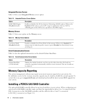
... operation to Enabled, the memory runs at full speed. Table 1-4. This rate should not be negotiated automatically with a SAS RAID controller, make sure that use TCP by offloading part of the memory. Integrated Devices Screen Table 1-4 lists a new Integrated Devices screen option. Serial Communication Screen Table 1-6 lists the updated information on the Memory screen. Table 1-5. When set to Enabled, I /OAT) option. Installing a PERC5i SAS RAID Controller The optional SAS RAID controller allows for drives 4 and 5 is connected to six hard drives...
... operation to Enabled, the memory runs at full speed. Table 1-4. This rate should not be negotiated automatically with a SAS RAID controller, make sure that use TCP by offloading part of the memory. Integrated Devices Screen Table 1-4 lists a new Integrated Devices screen option. Serial Communication Screen Table 1-6 lists the updated information on the Memory screen. Table 1-5. When set to Enabled, I /OAT) option. Installing a PERC5i SAS RAID Controller The optional SAS RAID controller allows for drives 4 and 5 is connected to six hard drives...


