
Dell PowerEdge 1900 Support Question
Dell PowerEdge 1900 Support Question
Find answers below for this question about Dell PowerEdge 1900.Need a Dell PowerEdge 1900 manual? We have 7 online manuals for this item!
Question posted by Gertdal on February 11th, 2014
How To Replace A Hot Pluggable Drive In A Poweredge 1900
The person who posted this question about this Dell product did not include a detailed explanation. Please use the "Request More Information" button to the right if more details would help you to answer this question.
Current Answers
Related Dell PowerEdge 1900 Manual Pages
Hardware Owner's Manual (PDF) - Page 5

... Removing the Diskette Drive 72 Installing the Diskette Drive Into the Drive Carrier 74 Installing the Diskette Drive 74
System Battery 75 Replacing the System Battery 75
Cooling Shroud 77 Removing the Cooling Shroud 77 Installing the Cooling Shroud 79
Fan Brackets 79 Removing the Center Fan Bracket 79 Replacing the Center Fan Bracket 79 Removing...
Hardware Owner's Manual (PDF) - Page 25
....dell.com or your Dell sales agent to
System Setup program. faulty or improperly seated memory module(s). If the problem persists, see "Troubleshooting a Diskette Drive" on page 80.
Replace the faulty DIMM as soon as possible.
See "Installing a RAC Card" on page 110. About Your System
25 Error: Memory failure detected. Ensure...
Hardware Owner's Manual (PDF) - Page 52
...hot-plug cooling fans: • One expansion-bay cooling fan (FAN1) • Two processor cooling fans, one for connector locations): • PWR1 connector on the system board • PWR2 connector on the system board • PWR CTRL connector on the system board • Hard drives • Diskette drive • Optical drive...module cooling fans:
- See "Replacing the Center Fan Bracket" on ...
Hardware Owner's Manual (PDF) - Page 67
...68. 12 Replace the center fan bracket. See Figure ...fans. If you are replacing the tape backup unit, ...on page 48. 8 Replace the bezel, if removed. See "Replacing the Center Fan Bracket... Card" on page 79. 13 Replace the fans into the center fan bracket...the Bezel" on page 48. 16 Replace the bezel, if removed.
7 Close...replacing the tape backup unit, insert the filler plate over the empty...
Hardware Owner's Manual (PDF) - Page 69
...:
a Push the spring latch at opposite ends of the way into the center fan bracket. NOTE: There is the last device in the drive kit to the drive. See "Replacing the Center Fan Bracket" on page 79.
14 Connect the SCSI interface cable to the SCSI connector on the optional SCSI controller card...
Hardware Owner's Manual (PDF) - Page 70
... cables to remove the system cover and access any attached peripherals, and disconnect the system from the bay. 11 Replace the optical drive or insert the filler plate over the empty drive slot. 12 Replace the center fan bracket. See Figure 3-15. 6 Remove the fans from the optional SCSI controller card and pull the...
Hardware Owner's Manual (PDF) - Page 110
....
See "Using the System Setup Program" on the system and attached peripherals.
Action CAUTION: Only trained service technicians are hot-pluggable.
See "Using Server Administrator Diagnostics" on page 121. 2 Turn on page 33.
If the replacement fan does not operate, see "Getting Help" on page 53. Before performing any procedure, see your Product Information...
Hardware Owner's Manual (PDF) - Page 114
...corrupted tape-backup software or tape drive device driver
• Defective SCSI controller
Action 1 Remove the tape cartridge you were using when the problem occurred, and replace it with a tape cartridge ...on page 121.
7 Open or remove the bezel. See "Using Server Administrator Diagnostics" on page 48. 10 Ensure that the tape drive is terminated or not terminated, based on page 46. 8 Turn ...
Hardware Owner's Manual (PDF) - Page 117
...Guide for your operating system and the expansion card.
See "Using Server Administrator Diagnostics" on page 92. See "Opening the System" on ...system from the electrical outlet. 4 Open the system. See
"Replacing the SAS RAID Controller Daughter Card Battery" on page 121. 2...48. 5 Ensure that the cable connections between the hard drive(s) and the SAS controller card or SAS RAID controller ...
Hardware Owner's Manual (PDF) - Page 164
..., 14 front-panel, 11
G
guidelines for memory installation, 82
H
hard drive troubleshooting, 115
hard drives, 59 installing, 61 removing, 59
hot-plug fans, 53 power supplies, 50
I
indicators back-panel, 14 front-..., 33 status LCD, 16 system, 23 warning, 30
microprocessor replacing, 88 troubleshooting, 118
mirroring memory, 83 mouse
troubleshooting, 104
N
NICs indicators, 15 troubleshooting, 106
NMI...
Information Update - Page 1
Dell™ PowerEdge™ 1900 Systems
Information Update
www.dell.com | support.dell.com
Installing a SATA Optical Drive - Page 1
Dell™ PowerEdge™ 19x0 and 29x0 Systems
Installing a SATA Optical Drive
Installing a SATA Optical Drive - Page 3

...cables from the front of the optical drive.
6 PowerEdge 2900 and 1900 systems only: Perform the following steps. Installing a SATA Optical Drive
These instructions apply to Dell™ PowerEdge™ systems to remove the system...the safety instructions that came with a drive tray, release the blue tab at the top of the peripheral bay and remove the optical drive from the back of the bay.
7...
Installing a SATA Optical Drive - Page 4
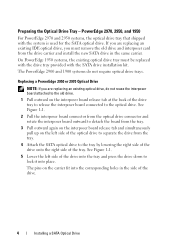
... of the tray. If you must be replaced with the drive tray provided with the system is used for the SATA optical drive. PowerEdge 2970, 2950, and 1950
For PowerEdge 2970 and 2950 systems, the optical drive tray that shipped with the SATA drive installation kit. The PowerEdge 2900 and 1900 systems do not reuse the interposer board attached...
Installing a SATA Optical Drive - Page 5

Release the rails to attach the drive to the old drive. Replacing the Optical Drive in a PowerEdge 2950 or 2970 System
2 1
3
4
5
6
7
1 optical drive 3 interposer 5 SATA power cable 7 optical drive carrier
2 interposer release latch 4 SATA cable 6 carrier latch
Replacing a PowerEdge 1950 Optical Drive
NOTE: The replacement drive tray provided in the installation kit must be used with ...
Installing a SATA Optical Drive - Page 6

... Figure 1-3. c Connect the cable to the power supply bays. PowerEdge 1950
1 Insert the optical drive tray into the system until it is fully inserted and locked into the cable path on the system board.
NOTE: You may need to replace the existing power cable with the branching power cable) to the power supply...
Installing a SATA Optical Drive - Page 7

... "SAS Controller Daughter Card" in your Hardware Owner's Manual.
7 Reconnect the system to the power supply connector.
PowerEdge 2970 or 2950
1 Insert the optical drive tray into the system until it is fully inserted and locked into position.
2 Connect the SATA cable (the end with the branching power cable) to ...
Installing a SATA Optical Drive - Page 8

... system board 2 cable retention bracket
3 SATA data cable
4 SATA power cable
5 optical drive
8
Installing a SATA Optical Drive Figure 1-4.
See "Removing the Cooling Shroud" in your Hardware Owner's Manual.
5 Remove ... from the chassis slots.
6 Route the SATA cable in the cable channel in the PowerEdge 2950 and 2970
1
2
3 4 5
1 SATA_B connector on the system board. See Figure 1-4.
...
Installing a SATA Optical Drive - Page 9

..., connect to an available power supply cable.
5 Replace the center fan bracket. For a PowerEdge 1900, use the SATA_B connector.
- See Figure 1-5.
-
See "Installing the Cooling Shroud" in the center fan bracket.
7 Route the SATA cable to the system board over the top of the optical drive.
4 Use the appropriate power cable provided in your...
Installing a SATA Optical Drive - Page 10

See "Closing the System" in a PowerEdge 2900 or 1900
3
2
4
5 1
1 optical drive 3 SATA data cable 5 SATA power connector on SAS
backplane (PowerEdge 2900 only)
2 SATA power cable 4 SATA connector on the system and attached peripherals.
10
Installing a SATA Optical Drive Figure 1-5. SATA Cable Routing in your Hardware Owner's Manual.
10 Reconnect the system to power and turn...
Similar Questions


