
Hardware Owner's Manual (PDF)
Page 28
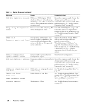
...If the problem persists, see "Troubleshooting Expansion Cards" on not found Seek error Seek operation failed Faulty diskette or hard drive. SATA port n hard disk drive SATA cables are securely shadowing. Plug & Play Configuration Error Error encountered in your system. faulty system board. See ..." on page 115 for jumper location. Install the NVRAM_CLR jumper and reboot the system. Replace the diskette. Ensure that faulty. Ensure that the diskette and hard drive cables are securely connected to install PCI device BIOS (Option ROM) Reseat the expansion cards...
...If the problem persists, see "Troubleshooting Expansion Cards" on not found Seek error Seek operation failed Faulty diskette or hard drive. SATA port n hard disk drive SATA cables are securely shadowing. Plug & Play Configuration Error Error encountered in your system. faulty system board. See ..." on page 115 for jumper location. Install the NVRAM_CLR jumper and reboot the system. Replace the diskette. Ensure that faulty. Ensure that the diskette and hard drive cables are securely connected to install PCI device BIOS (Option ROM) Reseat the expansion cards...
Hardware Owner's Manual (PDF)
Page 29
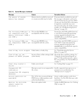
... on the boot hard drive. Timer chip counter 2 failed Faulty system board. Ensure that only ECC FBD1 memory is informative and can be faulty. Dell recommends purchasing memory upgrade kits directly from www.dell.com or your Dell sales agent to determine if single-bit or multi-bit errors were detected and replace the faulty memory...
... on the boot hard drive. Timer chip counter 2 failed Faulty system board. Ensure that only ECC FBD1 memory is informative and can be faulty. Dell recommends purchasing memory upgrade kits directly from www.dell.com or your Dell sales agent to determine if single-bit or multi-bit errors were detected and replace the faulty memory...
Hardware Owner's Manual (PDF)
Page 52
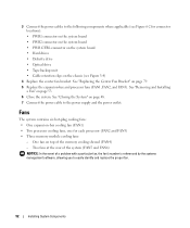
...; PWR1 connector on the system board • PWR2 connector on the system board • PWR CTRL connector on the system board • Hard drives • Diskette drive • Optical drive • Tape backup unit • Cable retention clips on the chassis (see Figure 6-2 for each processor (FAN2 and FAN3) •...top of a problem with a particular fan, the fan's number is referenced by the systems management software, allowing you to easily identify and replace the proper fan. 52 Installing System Components Two fans at the rear of the system (FAN5 and FAN6) NOTICE: In the event of ...
...; PWR1 connector on the system board • PWR2 connector on the system board • PWR CTRL connector on the system board • Hard drives • Diskette drive • Optical drive • Tape backup unit • Cable retention clips on the chassis (see Figure 6-2 for each processor (FAN2 and FAN3) •...top of a problem with a particular fan, the fan's number is referenced by the systems management software, allowing you to easily identify and replace the proper fan. 52 Installing System Components Two fans at the rear of the system (FAN5 and FAN6) NOTICE: In the event of ...
Hardware Owner's Manual (PDF)
Page 66
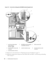
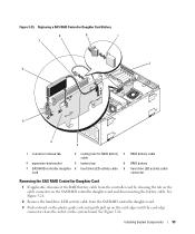
..." on page 79. 6 Replace the expansion-bay and processor fans (FAN1, FAN2, and FAN3). Six-hard-drive Configuration (SAS RAID Controller Daughter Card) 1 2 3 4 5 6 7 1 hard drive activity system board connector (HD_ACT_CARD) 2 SAS RAID controller daughter 3 SASx connector (2) card battery connector 4 hard drive LED activity cable 5 center fan retention cage connector 6 hard drive interface cable connector 7 hard drive power connector 5 Replace the center fan...
..." on page 79. 6 Replace the expansion-bay and processor fans (FAN1, FAN2, and FAN3). Six-hard-drive Configuration (SAS RAID Controller Daughter Card) 1 2 3 4 5 6 7 1 hard drive activity system board connector (HD_ACT_CARD) 2 SAS RAID controller daughter 3 SASx connector (2) card battery connector 4 hard drive LED activity cable 5 center fan retention cage connector 6 hard drive interface cable connector 7 hard drive power connector 5 Replace the center fan...
Hardware Owner's Manual (PDF)
Page 92
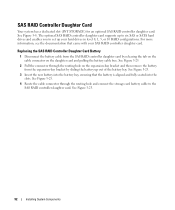
See Figure 3-8. The optional SAS RAID controller daughter card supports up to six SAS or SATA hard drives and enables you to the SAS RAID controller daughter card. Replacing the SAS RAID Controller Daughter Card Battery 1 Disconnect the battery cable from the SAS RAID controller daughter card by releasing the tab on the ...daughter card. For more information, see the documentation that the battery is aligned and fully seated into the battery bay, ensuring that came with your hard drives in level 0, 1, 5, or 10 RAID configurations. See Figure 3-25. 92 Installing System Components
See Figure 3-8. The optional SAS RAID controller daughter card supports up to six SAS or SATA hard drives and enables you to the SAS RAID controller daughter card. Replacing the SAS RAID Controller Daughter Card Battery 1 Disconnect the battery cable from the SAS RAID controller daughter card by releasing the tab on the ...daughter card. For more information, see the documentation that the battery is aligned and fully seated into the battery bay, ensuring that came with your hard drives in level 0, 1, 5, or 10 RAID configurations. See Figure 3-25. 92 Installing System Components
Hardware Owner's Manual (PDF)
Page 93
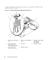
... 93 See Figure 3-26. Replacing a SAS RAID Controller Daughter Card Battery 8 9 1 7 2 6 5 4 3 1 connector release tab 2 routing hole for RAID battery 3 RAID battery cable cable 4 expansion-bay bracket 5 battery bay 6 RAID battery 7 SAS RAID controller daughter 8 hard drive LED activity cable 9 hard drive LED activity cable card connector Removing...the SAS RAID controller daughter card and disconnecting the battery cable. See Figure 3-26. 2 Remove the hard drive LED activity cable from the controller card by releasing the tab on the cable connector on the system board.
... 93 See Figure 3-26. Replacing a SAS RAID Controller Daughter Card Battery 8 9 1 7 2 6 5 4 3 1 connector release tab 2 routing hole for RAID battery 3 RAID battery cable cable 4 expansion-bay bracket 5 battery bay 6 RAID battery 7 SAS RAID controller daughter 8 hard drive LED activity cable 9 hard drive LED activity cable card connector Removing...the SAS RAID controller daughter card and disconnecting the battery cable. See Figure 3-26. 2 Remove the hard drive LED activity cable from the controller card by releasing the tab on the cable connector on the system board.
Hardware Owner's Manual (PDF)
Page 94
... RAID controller daughter 2 card 4 hard drive LED activity 5 indicator system board connector (HD_ACT_CARD) 7 hard drive LED activity 8 indicator cable connector RAID battery cable (SAS RAID 3 only) slide rails (2) 6 SAS RAID connector 1 SAS RAID controller daughter card slot socket (INT_STORAGE) SAS RAID connector 0 94 Installing System Components Figure 3-26. To replace the SAS RAID controller daughter...
... RAID controller daughter 2 card 4 hard drive LED activity 5 indicator system board connector (HD_ACT_CARD) 7 hard drive LED activity 8 indicator cable connector RAID battery cable (SAS RAID 3 only) slide rails (2) 6 SAS RAID connector 1 SAS RAID controller daughter card slot socket (INT_STORAGE) SAS RAID connector 0 94 Installing System Components Figure 3-26. To replace the SAS RAID controller daughter...
Hardware Owner's Manual (PDF)
Page 95
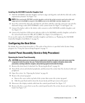
...system chassis and remove the board. See Figure 3-25. 4 Connect the hard drive LED activity indicator cable to the SAS RAID controller daughter card and to replace the SAS RAID controller daughter card battery, see "Replacing the SAS RAID Controller Daughter Card Battery" on page 33. Installing System... 6 Remove the three screws that secures the system top panel. If you need to the system board connector (HD_ACT_CARD). Configuring the Boot Drive By default, the system boots from the electrical outlet and peripherals. 3 Open the system. The order of boot devices is specified in ...
...system chassis and remove the board. See Figure 3-25. 4 Connect the hard drive LED activity indicator cable to the SAS RAID controller daughter card and to replace the SAS RAID controller daughter card battery, see "Replacing the SAS RAID Controller Daughter Card Battery" on page 33. Installing System... 6 Remove the three screws that secures the system top panel. If you need to the system board connector (HD_ACT_CARD). Configuring the Boot Drive By default, the system boots from the electrical outlet and peripherals. 3 Open the system. The order of boot devices is specified in ...
Hardware Owner's Manual (PDF)
Page 117
...Replacing the SAS RAID Controller Daughter Card Battery" on page 131. • If you have a SAS RAID controller daughter card, ensure that the following RAID components are authorized to its connector. Action CAUTION: Only trained service technicians are properly installed and connected: • Memory module • Battery 10 Verify that the hard drive... LED activity indicator cable is firmly seated in their connectors. 12 Verify that the cable connections between the hard drive(s) and the SAS controller card or SAS RAID ...
...Replacing the SAS RAID Controller Daughter Card Battery" on page 131. • If you have a SAS RAID controller daughter card, ensure that the following RAID components are authorized to its connector. Action CAUTION: Only trained service technicians are properly installed and connected: • Memory module • Battery 10 Verify that the hard drive... LED activity indicator cable is firmly seated in their connectors. 12 Verify that the cable connections between the hard drive(s) and the SAS controller card or SAS RAID ...
Hardware Owner's Manual (PDF)
Page 164
..., 54 fans, 52 installing and removing, 53 numbered, 53 features back-panel, 14 front-panel, 11 G guidelines for memory installation, 82 H hard drive troubleshooting, 115 hard drives, 59 installing, 61 removing, 59 hot-plug fans, 53 power supplies, 50 I indicators back-panel, 14 front-panel, 11 LCD, 16 NIC... socket arrangement, 81 sparing, 82 troubleshooting, 110 messages alert, 31 error, 33 status LCD, 16 system, 23 warning, 30 microprocessor replacing, 88 troubleshooting, 118 mirroring memory, 83 mouse troubleshooting, 104 N NICs indicators, 15 troubleshooting, 106 NMI button, 12 164 Index
..., 54 fans, 52 installing and removing, 53 numbered, 53 features back-panel, 14 front-panel, 11 G guidelines for memory installation, 82 H hard drive troubleshooting, 115 hard drives, 59 installing, 61 removing, 59 hot-plug fans, 53 power supplies, 50 I indicators back-panel, 14 front-panel, 11 LCD, 16 NIC... socket arrangement, 81 sparing, 82 troubleshooting, 110 messages alert, 31 error, 33 status LCD, 16 system, 23 warning, 30 microprocessor replacing, 88 troubleshooting, 118 mirroring memory, 83 mouse troubleshooting, 104 N NICs indicators, 15 troubleshooting, 106 NMI button, 12 164 Index
Hardware Owner's Manual (PDF)
Page 165
...bay bracket, 98 fans, 53 hard drives, 59 memory, 85 optical drive, 70 power supply, 50 processor, 88 system board, 97 tape backup unit, 67 S safety, 101 SAS controller. See SAS controller daughter card SAS RAID controller daughter card battery replacement, 92 troubleshooting, 116 securing ...your system, 42 serial I/O device troubleshooting, 105 setup password assigning, 43 changing, 44 using, 43 spare bank, 82 startup accessing system features, 10 status messages LCD, 16 systems management, 23 support contacting Dell, 136 system...
...bay bracket, 98 fans, 53 hard drives, 59 memory, 85 optical drive, 70 power supply, 50 processor, 88 system board, 97 tape backup unit, 67 S safety, 101 SAS controller. See SAS controller daughter card SAS RAID controller daughter card battery replacement, 92 troubleshooting, 116 securing ...your system, 42 serial I/O device troubleshooting, 105 setup password assigning, 43 changing, 44 using, 43 spare bank, 82 startup accessing system features, 10 status messages LCD, 16 systems management, 23 support contacting Dell, 136 system...


