Command Line Interface Guide
Page 123
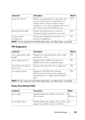
... ports. Power Over Ethernet (PoE) Command power inline power inline legacy Description Mode* Enables/disables the ability of a copper cable attached to a port. Command Description Mode* passwords lock-out Enables the administrator to strengthen the GC security of the switch to...When a lockout count is configured, a user who is logging in must enter the correct password within that count. show copper-ports cable- IC (Ethernet ) Enables/disables the ability of the switch by enabling the user lockout feature. show passwords configuration Displays the configuration...
... ports. Power Over Ethernet (PoE) Command power inline power inline legacy Description Mode* Enables/disables the ability of a copper cable attached to a port. Command Description Mode* passwords lock-out Enables the administrator to strengthen the GC security of the switch to...When a lockout count is configured, a user who is logging in must enter the correct password within that count. show copper-ports cable- IC (Ethernet ) Enables/disables the ability of the switch by enabling the user lockout feature. show passwords configuration Displays the configuration...

Command Line Interface Guide
Page 1163
60 PHY Diagnostics Commands This chapter explains the following commands: • show copper-ports cable-length • show copper-ports tdr • show fiber-ports optical-transceiver • test copper-port tdr PHY Diagnostics Commands 1163
60 PHY Diagnostics Commands This chapter explains the following commands: • show copper-ports cable-length • show copper-ports tdr • show fiber-ports optical-transceiver • test copper-port tdr PHY Diagnostics Commands 1163

Command Line Interface Guide
Page 1164
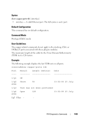
... port must be active and working in Privileged EXEC mode to display the estimated copper cable length attached to all ports. Syntax show copper-ports cable-length command in a 100M or 1000M mode. console#show copper-ports cable-length Port Length [meters] ---- 1/g1 A valid Ethernet port. Example The following example displays the estimated...
... port must be active and working in Privileged EXEC mode to display the estimated copper cable length attached to all ports. Syntax show copper-ports cable-length command in a 100M or 1000M mode. console#show copper-ports cable-length Port Length [meters] ---- 1/g1 A valid Ethernet port. Example The following example displays the estimated...
Command Line Interface Guide
Page 1165
... 10GBaseT ports associated with these plug-in modules. Example The following example displays the last TDR tests on all ports. The maximum length of the cable for the Time Domain Reflectometry (TDR) test is unit / port. PHY Diagnostics Commands 1165 A valid Ethernet port. Syntax show copper-ports tdr Port Result Length...
... 10GBaseT ports associated with these plug-in modules. Example The following example displays the last TDR tests on all ports. The maximum length of the cable for the Time Domain Reflectometry (TDR) test is unit / port. PHY Diagnostics Commands 1165 A valid Ethernet port. Syntax show copper-ports tdr Port Result Length...

Command Line Interface Guide
Page 1167
... unit / port. Internally measured transceiver temperature Voltage - Measured TX output power in milliWatts TX Fault - Loss of a copper cable attached to a port. Default Configuration This command has no default configuration. Syntax test copper-port tdr interface • interface -...(TDR) technology the quality and characteristics of signal test copper-port tdr Use the test copper-port tdr command in a report on the cable attached to diagnose with an active fiber port. Temp - Internally measured supply voltage Current - Measured RX received power in milliWatts Input Power ...
... unit / port. Internally measured transceiver temperature Voltage - Measured TX output power in milliWatts TX Fault - Loss of a copper cable attached to a port. Default Configuration This command has no default configuration. Syntax test copper-port tdr interface • interface -...(TDR) technology the quality and characteristics of signal test copper-port tdr Use the test copper-port tdr command in a report on the cable attached to diagnose with an active fiber port. Temp - Internally measured supply voltage Current - Measured RX received power in milliWatts Input Power ...

Command Line Interface Guide
Page 1168
console#test copper-port tdr 2/g3 Can't perform the test on the cable attached to port 2/g3. The following example results in a failure to report on fiber ports 1168 PHY Diagnostics Commands
console#test copper-port tdr 2/g3 Can't perform the test on the cable attached to port 2/g3. The following example results in a failure to report on fiber ports 1168 PHY Diagnostics Commands
User's Guide
Page 4
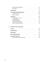
Device Management Buttons 44 Check Boxes 45 Defining Fields 45 Accessing the Switch Through the CLI 45 Console Connection 46 Telnet Connection 46 Using the CLI 46 Command Mode Overview 46 User EXEC Mode 47 Privileged EXEC Mode 47 Global Configuration Mode 48 Interface Configuration Mode 48 3 Cable and Port Information Overview 49 Ethernet Interface 50 SFP Interfaces 51 Bay 1 and Bay 2 Interfaces 52 Serial Cable Connection 52 Connecting the Switch to a Terminal 52 4
Device Management Buttons 44 Check Boxes 45 Defining Fields 45 Accessing the Switch Through the CLI 45 Console Connection 46 Telnet Connection 46 Using the CLI 46 Command Mode Overview 46 User EXEC Mode 47 Privileged EXEC Mode 47 Global Configuration Mode 48 Interface Configuration Mode 48 3 Cable and Port Information Overview 49 Ethernet Interface 50 SFP Interfaces 51 Bay 1 and Bay 2 Interfaces 52 Serial Cable Connection 52 Connecting the Switch to a Terminal 52 4

User's Guide
Page 7
... 144 Default Domain Name 145 Host Name Mapping 146 Dynamic Host Name Mapping 148 ARP Table 149 IPv6 Management Features 150 Running Cable Diagnostics 152 Integrated Cable Test for Copper Cables 152 Optical Transceiver Diagnostics 154 Managing Device Security 157 Access Profile 157 Authentication Profiles 162 Select Authentication 166 Password Management 169 Local...
... 144 Default Domain Name 145 Host Name Mapping 146 Dynamic Host Name Mapping 148 ARP Table 149 IPv6 Management Features 150 Running Cable Diagnostics 152 Integrated Cable Test for Copper Cables 152 Optical Transceiver Diagnostics 154 Managing Device Security 157 Access Profile 157 Authentication Profiles 162 Select Authentication 166 Password Management 169 Local...
User's Guide
Page 25
...and the packets at the end of their transmission capabilities. Introduction 25 Port advertisement allows the system administrator to prevent buffer overflows. The PowerConnect 6200 Series enhances auto negotiation by traffic competing for additional traffic. Transmissions are forwarded before packets at the head of the queue are ...that share a point-to-point link segment, and to automatically configure both switches to exchange information between crossed and straight-through cables. Media-Dependent Interface (MDI) is unavailable for the same egress port resources.
...and the packets at the end of their transmission capabilities. Introduction 25 Port advertisement allows the system administrator to prevent buffer overflows. The PowerConnect 6200 Series enhances auto negotiation by traffic competing for additional traffic. Transmissions are forwarded before packets at the head of the queue are ...that share a point-to-point link segment, and to automatically configure both switches to exchange information between crossed and straight-through cables. Media-Dependent Interface (MDI) is unavailable for the same egress port resources.
User's Guide
Page 45
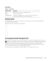
... is connected to the device prior to a configuration page. For information about configuring an initial IP Address, see "Configuration Overview." Using Dell™ OpenManage™ Switch Administrator 45 To enable a configuration item, i.e., adjust sensitivity of the stack. NOTE: If you to using... device has an IP address defined and that takes you are managing a stack, ensure the serial interface cable is similar to entering commands on the Dell OpenManage Switch Administrator Web page. Check Boxes Check Box Type Add Remove General selection Description Hyperlink that the ...
... is connected to the device prior to a configuration page. For information about configuring an initial IP Address, see "Configuration Overview." Using Dell™ OpenManage™ Switch Administrator 45 To enable a configuration item, i.e., adjust sensitivity of the stack. NOTE: If you to using... device has an IP address defined and that takes you are managing a stack, ensure the serial interface cable is similar to entering commands on the Dell OpenManage Switch Administrator Web page. Check Boxes Check Box Type Add Remove General selection Description Hyperlink that the ...
User's Guide
Page 46
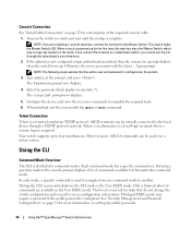
...terminal to a subordinate switch, you are available in the stack. Type admin at the console prompt displays a list of the required console cable. 1. Configure the device and enter the necessary commands to a local login terminal where a remote login is required. When a stack is... powered up enable passwords. 46 Using Dell™ OpenManage™ Switch Administrator If you connect the terminal to the Master Switch. The console# prompt now displays. 5. Your switch...
...terminal to a subordinate switch, you are available in the stack. Type admin at the console prompt displays a list of the required console cable. 1. Configure the device and enter the necessary commands to a local login terminal where a remote login is required. When a stack is... powered up enable passwords. 46 Using Dell™ OpenManage™ Switch Administrator If you connect the terminal to the Master Switch. The console# prompt now displays. 5. Your switch...
User's Guide
Page 49
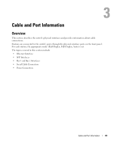
For each station, the appropriate mode (Half-Duplex, Full-Duplex, Auto) is set. The topics covered in this section include: • Ethernet Interface • SFP Interfaces • Bay 1 and Bay 2 Interfaces • Serial Cable Connection • Power Connection Cable and Port Information 49 Stations are connected to the switch's ports through the physical interface ports on the front panel. 3 Cable and Port Information Overview This section describes the switch's physical interfaces and provides information about cable connections.
For each station, the appropriate mode (Half-Duplex, Full-Duplex, Auto) is set. The topics covered in this section include: • Ethernet Interface • SFP Interfaces • Bay 1 and Bay 2 Interfaces • Serial Cable Connection • Power Connection Cable and Port Information 49 Stations are connected to the switch's ports through the physical interface ports on the front panel. 3 Cable and Port Information Overview This section describes the switch's physical interfaces and provides information about cable connections.
User's Guide
Page 50
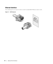
RJ-45 Connector 50 Cable and Port Information Ethernet Interface The switching port can connect to stations wired in standard RJ-45 Ethernet station mode. Figure 3-1.
RJ-45 Connector 50 Cable and Port Information Ethernet Interface The switching port can connect to stations wired in standard RJ-45 Ethernet station mode. Figure 3-1.
User's Guide
Page 51
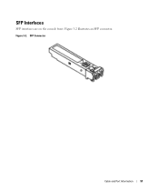
Figure 3-2 illustrates an SFP connector. SFP Connector Cable and Port Information 51 SFP Interfaces SFP interfaces are on the console front. Figure 3-2.
Figure 3-2 illustrates an SFP connector. SFP Connector Cable and Port Information 51 SFP Interfaces SFP interfaces are on the console front. Figure 3-2.

User's Guide
Page 52
... 2 Interfaces The Dell™ PowerConnect™ 6200series switches support dual 10 Gb slot interfaces. Connecting the Switch to female DB-9 crossover cable. The switch's serial cable is a female to a Terminal 1. Bay 1 and Bay 2 PowerConnect 6200 Series 10 Gb Slots Serial Cable Connection You can use a computer running terminal emulation software). Connect the serial cable to the serial...
... 2 Interfaces The Dell™ PowerConnect™ 6200series switches support dual 10 Gb slot interfaces. Connecting the Switch to female DB-9 crossover cable. The switch's serial cable is a female to a Terminal 1. Bay 1 and Bay 2 PowerConnect 6200 Series 10 Gb Slots Serial Cable Connection You can use a computer running terminal emulation software). Connect the serial cable to the serial...
User's Guide
Page 53
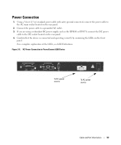
Connect the power cable to PowerConnect 6200 Series To DC power source To AC power source Cable and Port Information 53 Confirm that the device is connected and operating correctly by examining the LEDs on the rear panel. 4. For a complete explanation of ... 3-5. AC Power Connection to a grounded AC outlet. 3. If you are using a redundant DC power supply, such as the RPS600 or EPS470, connect the DC power cable to the AC main socket located on the rear panel. 2. Power Connection 1. Using a 5-foot (1.5 m) standard power...
Connect the power cable to PowerConnect 6200 Series To DC power source To AC power source Cable and Port Information 53 Confirm that the device is connected and operating correctly by examining the LEDs on the rear panel. 4. For a complete explanation of ... 3-5. AC Power Connection to a grounded AC outlet. 3. If you are using a redundant DC power supply, such as the RPS600 or EPS470, connect the DC power cable to the AC main socket located on the rear panel. 2. Power Connection 1. Using a 5-foot (1.5 m) standard power...

User's Guide
Page 54
54 Cable and Port Information
54 Cable and Port Information
User's Guide
Page 58
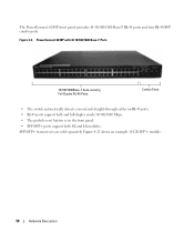
... button is on RJ-45 ports. • RJ-45 ports support half- Figure 4-12 shows an example 10 GE SFP+ module. 58 Hardware Description The PowerConnect 6248P front panel provides 44 10/100/1000 Base-T RJ-45 ports and four RJ-45/SFP combo ports.... PowerConnect 6248P with 48 10/100/1000 Base-T Ports 10/100/1000Base-T Auto-sensing Full Duplex RJ-45 Ports Combo Ports • The switch automatically detects crossed and straight-through cables on the front panel. • SFP/SFP+ ports support both...
... button is on RJ-45 ports. • RJ-45 ports support half- Figure 4-12 shows an example 10 GE SFP+ module. 58 Hardware Description The PowerConnect 6248P front panel provides 44 10/100/1000 Base-T RJ-45 ports and four RJ-45/SFP combo ports.... PowerConnect 6248P with 48 10/100/1000 Base-T Ports 10/100/1000Base-T Auto-sensing Full Duplex RJ-45 Ports Combo Ports • The switch automatically detects crossed and straight-through cables on the front panel. • SFP/SFP+ ports support both...

User's Guide
Page 61
Connect the terminal to the switch and is 9600 bps. If you connect the terminal to a subordinate switch, you need to assemble and cable the stack before powering up for management through a serial interface. Hardware Description 61 NOTE: The console port supports asynchronous data of switches, you will not ...
Connect the terminal to the switch and is 9600 bps. If you connect the terminal to a subordinate switch, you need to assemble and cable the stack before powering up for management through a serial interface. Hardware Description 61 NOTE: The console port supports asynchronous data of switches, you will not ...
User's Guide
Page 62
... the switch directly below it. Use the remaining stacking cable to connect the remaining free ports, one of the devices are connected. 4. See "System LEDs" for information on the next switch. 3. You can stack up to 12 PowerConnect 6224 and/or 6248 switches, supporting up to 576 front... panel ports. For each on the left side of the switch rear. Ventilation System Three fans cool the PowerConnect 6224. Stacking You can verify operation by connecting adjacent units using the stacking ports on the top and bottom switches. 62 Hardware Description Connect...
... the switch directly below it. Use the remaining stacking cable to connect the remaining free ports, one of the devices are connected. 4. See "System LEDs" for information on the next switch. 3. You can stack up to 12 PowerConnect 6224 and/or 6248 switches, supporting up to 576 front... panel ports. For each on the left side of the switch rear. Ventilation System Three fans cool the PowerConnect 6224. Stacking You can verify operation by connecting adjacent units using the stacking ports on the top and bottom switches. 62 Hardware Description Connect...


