User Guide
Page 36
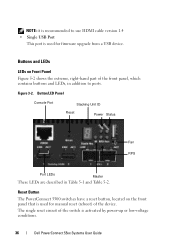
...-up or low-voltage conditions. 36 Dell PowerConnect 55xx Systems User Guide Reset Button The PowerConnect 5500 switches have a reset button, located on Front Panel Figure 5-2 shows the extreme, right-hand part of the device. The single reset circuit of the switch is used for manual reset (reboot) of the front panel, which contains buttons and LEDs, in Table 5-1 and...
...-up or low-voltage conditions. 36 Dell PowerConnect 55xx Systems User Guide Reset Button The PowerConnect 5500 switches have a reset button, located on Front Panel Figure 5-2 shows the extreme, right-hand part of the device. The single reset circuit of the switch is used for manual reset (reboot) of the front panel, which contains buttons and LEDs, in Table 5-1 and...

User Guide
Page 37
See "Unit Identification (Location)" on page 367 for more information. Dell PowerConnect 55xx Systems User Guide 37 Connector for more information about this feature. • RPS/MPS - PowerConnect 5524/48/P Back Panel Locator Fan MPS Fan A/C Power Supply The elements on page 42 for auxiliary ..., and two fan outlets. This LED is lit when the Unit Identification feature is selected. Figure 3-3. PowerConnect 5524/48 Back Panel Locator RPS A/C Power Supply Figure 3-4. The Reset button does not extend beyond the unit's front, and it must be activated with a pin. Back Panel...
See "Unit Identification (Location)" on page 367 for more information. Dell PowerConnect 55xx Systems User Guide 37 Connector for more information about this feature. • RPS/MPS - PowerConnect 5524/48/P Back Panel Locator Fan MPS Fan A/C Power Supply The elements on page 42 for auxiliary ..., and two fan outlets. This LED is lit when the Unit Identification feature is selected. Figure 3-3. PowerConnect 5524/48 Back Panel Locator RPS A/C Power Supply Figure 3-4. The Reset button does not extend beyond the unit's front, and it must be activated with a pin. Back Panel...
User Guide
Page 50
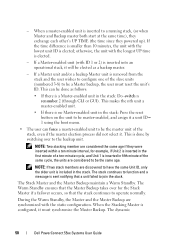
... stack: Do -switch n renumber 2 (through CLI or GUI). The stack continues to function and a message is a Master-enabled unit in the stack: Press the reset button on the unit to be master-enabled, and assign it a unit ID= 1 using the boot menu. • The user can force a master-enabled unit to... that the stack continues to the backup unit. The Warm Standby ensures that the Master Backup takes over to operate normally. The dynamic 50 Dell PowerConnect 55xx Systems User Guide This can be done as a backup master. - - If a Master-enabled unit (with the static configuration.
... stack: Do -switch n renumber 2 (through CLI or GUI). The stack continues to function and a message is a Master-enabled unit in the stack: Press the reset button on the unit to be master-enabled, and assign it a unit ID= 1 using the boot menu. • The user can force a master-enabled unit to... that the stack continues to the backup unit. The Warm Standby ensures that the Master Backup takes over to operate normally. The dynamic 50 Dell PowerConnect 55xx Systems User Guide This can be done as a backup master. - - If a Master-enabled unit (with the static configuration.
User Guide
Page 89
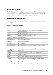
... Go to the selected target ports. If Select All is selected, all counters. Dell PowerConnect 55xx Systems User Guide 89 All letters or characters can be used, except the ... that are removed. Table 7-4. Copy the parameters from port Details Next Query Remove Reset All Counters Restore Defaults Description Save changes entered in page to previous page. Delete ... further details relevant to the Running Configuration file. Delete statistics. Common GUI Elements Button Apply Back Cancel Clear All Counters Clear Counters Clear Log Clear Statistics Copy parameters from...
... Go to the selected target ports. If Select All is selected, all counters. Dell PowerConnect 55xx Systems User Guide 89 All letters or characters can be used, except the ... that are removed. Table 7-4. Copy the parameters from port Details Next Query Remove Reset All Counters Restore Defaults Description Save changes entered in page to previous page. Delete ... further details relevant to the Running Configuration file. Delete statistics. Common GUI Elements Button Apply Back Cancel Clear All Counters Clear Counters Clear Log Clear Statistics Copy parameters from...
User Guide
Page 719
FOR PROOF ONLY 719 FILE LOCATION: C:\Users\gina\Desktop\Checkout_new\Maintenance Projects\Dell Contax\Dell_ContaxUG_PrintIX.fm RADIUS Advertisement 706 Rules 255 RADIUS client 28 RADIUS discovery 706 Running Configuration File 330, 706 RADIUS server 284 RAM Log 193 S ... Service 284 Server 707 Set Terminal Baud-Rate 78 Setup Wizard 58 Remote Log Server 199 sFlow 369 Remote Monitoring 26, 706 sFlow interface 374 Reset button 36 sFlow receiver 371 Retrieving an IP Address 68 sFlow statistics 376 RMON 615, 618, 619, 706 SFP 42 RMON Statistics 615, 616 SFP LEDs...
FOR PROOF ONLY 719 FILE LOCATION: C:\Users\gina\Desktop\Checkout_new\Maintenance Projects\Dell Contax\Dell_ContaxUG_PrintIX.fm RADIUS Advertisement 706 Rules 255 RADIUS client 28 RADIUS discovery 706 Running Configuration File 330, 706 RADIUS server 284 RAM Log 193 S ... Service 284 Server 707 Set Terminal Baud-Rate 78 Setup Wizard 58 Remote Log Server 199 sFlow 369 Remote Monitoring 26, 706 sFlow interface 374 Reset button 36 sFlow receiver 371 Retrieving an IP Address 68 sFlow statistics 376 RMON 615, 618, 619, 706 SFP 42 RMON Statistics 615, 616 SFP LEDs...


