
User's Guide
Page 12
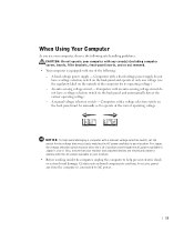
...unless the AC adapter cable has been disconnected from the electrical outlet. • When you use a surge suppressor, line conditioner, or uninterruptible power supply (UPS). • Ensure that nothing rests on your computer's cables and that the cables are not located where they can cause fire or...a bed, sofa, or rug. • Do not spill food or liquids on your computer, and then from the network jack. www.dell.com | support.dell.com CAUTION: Safety Instructions (continued) • To avoid shorting out your computer when disconnecting a network cable, first unplug the cable from the...
...unless the AC adapter cable has been disconnected from the electrical outlet. • When you use a surge suppressor, line conditioner, or uninterruptible power supply (UPS). • Ensure that nothing rests on your computer's cables and that the cables are not located where they can cause fire or...a bed, sofa, or rug. • Do not spill food or liquids on your computer, and then from the network jack. www.dell.com | support.dell.com CAUTION: Safety Instructions (continued) • To avoid shorting out your computer when disconnecting a network cable, first unplug the cable from the...
User's Guide
Page 13
... for the voltage that your monitor and attached devices are electrically rated to operate with the AC power available in Japan is connected to AC power. 11 A fixed-voltage power supply - Certain system board components continue to receive power any cover(s) (including computer covers, bezels, filler brackets, front-panel inserts, and so on the back...
... for the voltage that your monitor and attached devices are electrically rated to operate with the AC power available in Japan is connected to AC power. 11 A fixed-voltage power supply - Certain system board components continue to receive power any cover(s) (including computer covers, bezels, filler brackets, front-panel inserts, and so on the back...
User's Guide
Page 34
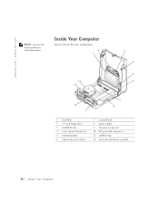
www.dell.com | support.dell.com NOTE: User service access points are colorcoded green. Inside Your Computer Small Form-Factor Computer 2 1 12 11 3 4 5 6 10 9 7 8 1 hard drive 2 3.5-inch floppy drive 3 CD/DVD drive 4 cover release buttons (2) 5 internal speaker 6 chassis intrusion switch 7 system board 8 power supply 9 AC power connector 10 I/O ports and connectors 11 padlock ring 12 heat sink and blower assembly 32 About Yo ur Computer
www.dell.com | support.dell.com NOTE: User service access points are colorcoded green. Inside Your Computer Small Form-Factor Computer 2 1 12 11 3 4 5 6 10 9 7 8 1 hard drive 2 3.5-inch floppy drive 3 CD/DVD drive 4 cover release buttons (2) 5 internal speaker 6 chassis intrusion switch 7 system board 8 power supply 9 AC power connector 10 I/O ports and connectors 11 padlock ring 12 heat sink and blower assembly 32 About Yo ur Computer

User's Guide
Page 35
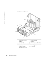
Small Desktop Computer 14 1 13 2 12 3 11 4 10 9 8 7 5 6 1 cover release buttons (2) 2 hard drive 3 internal speaker 4 chassis intrusion switch 5 expansion-card cage 6 power supply 7 expansion-card slots 8 AC power connector 9 padlock ring 10 I/O ports and connectors 11 heat sink and blower assembly 12 system board 13 3.5-inch floppy drive 14 CD/DVD drive A bout Yo ur Computer 33
Small Desktop Computer 14 1 13 2 12 3 11 4 10 9 8 7 5 6 1 cover release buttons (2) 2 hard drive 3 internal speaker 4 chassis intrusion switch 5 expansion-card cage 6 power supply 7 expansion-card slots 8 AC power connector 9 padlock ring 10 I/O ports and connectors 11 heat sink and blower assembly 12 system board 13 3.5-inch floppy drive 14 CD/DVD drive A bout Yo ur Computer 33
User's Guide
Page 36
www.dell.com | support.dell.com Small Mini-Tower Computer 13 1 2 12 11 10 3 9 4 8 5 7 6 1 cover release buttons (2) 2 hard drive 3 internal speaker 4 chassis intrusion switch 5 system board 6 expansion-card slots 7 I/O ports and connectors 8 AC power connector 9 padlock ring 10 microprocessor and airflow shroud 11 power supply 12 3.5-inch floppy drive 13 CD/DVD drive 34 About Yo ur Computer
www.dell.com | support.dell.com Small Mini-Tower Computer 13 1 2 12 11 10 3 9 4 8 5 7 6 1 cover release buttons (2) 2 hard drive 3 internal speaker 4 chassis intrusion switch 5 system board 6 expansion-card slots 7 I/O ports and connectors 8 AC power connector 9 padlock ring 10 microprocessor and airflow shroud 11 power supply 12 3.5-inch floppy drive 13 CD/DVD drive 34 About Yo ur Computer

User's Guide
Page 162
www.dell.com | support.dell.com Diagnostic lights Standby power light Power DC power supply: Wattage Heat dissipation Voltage Backup battery Physical Small form-factor computer: Height Width Depth Weight Small desktop computer: Height Width Depth Weight Small mini-tower ...
www.dell.com | support.dell.com Diagnostic lights Standby power light Power DC power supply: Wattage Heat dissipation Voltage Backup battery Physical Small form-factor computer: Height Width Depth Weight Small desktop computer: Height Width Depth Weight Small mini-tower ...
User's Guide
Page 180
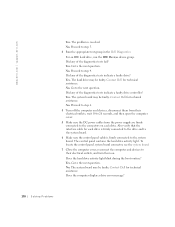
... No. Proceed to the next question. Yes. The system board may be faulty. Also verify that the interface cable for technical assistance. Contact Dell for each drive. To locate the control panel system board connector, see the system board. 7 Close the computer cover, reconnect the computer and...and turn them from their electrical outlets, wait 10 to 20 seconds, and then open the computer cover. 5 Make sure the DC power cables from the power supply are firmly connected to the next question. Go to the connectors on . Does the computer display a drive error message? 178 Solving ...
... No. Proceed to the next question. Yes. The system board may be faulty. Also verify that the interface cable for technical assistance. Contact Dell for each drive. To locate the control panel system board connector, see the system board. 7 Close the computer cover, reconnect the computer and...and turn them from their electrical outlets, wait 10 to 20 seconds, and then open the computer cover. 5 Make sure the DC power cables from the power supply are firmly connected to the next question. Go to the connectors on . Does the computer display a drive error message? 178 Solving ...
User's Guide
Page 187
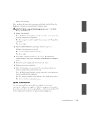
...Go to their electrical outlets, wait 10 to 20 seconds, and then open the computer cover. 4 Rotate the power supply away from a defective system board component, a faulty power supply, or a defective component connected to update the memory count. Go to step 3. 3 Turn off the computer and...the memory module(s). 6 Close the computer cover, reconnect the computer and devices to step 2. 2 Run the System Memory test group in the Dell Diagnostics. If an error message indicates a system board problem, fill out the Diagnostic Checklist as you perform this procedure, see "CAUTION: Safety...
...Go to their electrical outlets, wait 10 to 20 seconds, and then open the computer cover. 4 Rotate the power supply away from a defective system board component, a faulty power supply, or a defective component connected to update the memory count. Go to step 3. 3 Turn off the computer and...the memory module(s). 6 Close the computer cover, reconnect the computer and devices to step 2. 2 Run the System Memory test group in the Dell Diagnostics. If an error message indicates a system board problem, fill out the Diagnostic Checklist as you perform this procedure, see "CAUTION: Safety...
User's Guide
Page 188
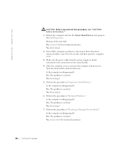
... their electrical outlets, wait 10 to 20 seconds, and then open the computer cover. 3 Make sure the power cables from the power supply are firmly connected to the connectors on . Did any of the tests fail? Contact Dell for technical assistance. 186 Solving Problems No. Yes. Go to step 6. 6 Perform the procedure in "Resetting...
... their electrical outlets, wait 10 to 20 seconds, and then open the computer cover. 3 Make sure the power cables from the power supply are firmly connected to the connectors on . Did any of the tests fail? Contact Dell for technical assistance. 186 Solving Problems No. Yes. Go to step 6. 6 Perform the procedure in "Resetting...

User's Guide
Page 248
... a nominal value no larger than 16 amperes (A). A protection mark "B" confirms that works together (computer, monitor, printer, and so on) should have the same power supply source. www.dell.com | support.dell.com Polish Center for Testing and Certification Notice The equipment should be located near the equipment and easily accessible. The phasing conductor of...
... a nominal value no larger than 16 amperes (A). A protection mark "B" confirms that works together (computer, monitor, printer, and so on) should have the same power supply source. www.dell.com | support.dell.com Polish Center for Testing and Certification Notice The equipment should be located near the equipment and easily accessible. The phasing conductor of...
User's Guide
Page 295
...States, many local electrical and building codes and ordinances require that is loaded, stays in RAM after the primary power source is a two-layer system. UPS Uninterruptible power supply. TCP/IP Transmission Control Protocol (TCP)/Internet Protocol (IP). See IP and IP Address. A hard drive protocol...of keys. The receiving computer's TCP layer reassembles the packets into smaller packets that it is terminated, and can also provide protection against power surges. 43 It can also be used in a private network. TSR Terminate-and-stay-resident. UDMA Ultra DMA. Typically, a ...
...States, many local electrical and building codes and ordinances require that is loaded, stays in RAM after the primary power source is a two-layer system. UPS Uninterruptible power supply. TCP/IP Transmission Control Protocol (TCP)/Internet Protocol (IP). See IP and IP Address. A hard drive protocol...of keys. The receiving computer's TCP layer reassembles the packets into smaller packets that it is terminated, and can also provide protection against power surges. 43 It can also be used in a private network. TSR Terminate-and-stay-resident. UDMA Ultra DMA. Typically, a ...

User's Guide
Page 297
... Remote Wake Up. WOL is also compatible with no stress applied to be installed or removed with current and emerging industry specifications, such as circuitry, power supply, network adapter, and so on. A type of WBEM standards, developed by DMTF, include a data model, the CIM standard, a coding specification, and an ...-Based Enterprise Management. WfM technology is used in a client computer, in such components as ACPI, CIM, SMBIOS, SNMP, and WBEM. A measurement of electrical power that allows a computer on a network to be remotely turned on or awakened from sleep mode.
... Remote Wake Up. WOL is also compatible with no stress applied to be installed or removed with current and emerging industry specifications, such as circuitry, power supply, network adapter, and so on. A type of WBEM standards, developed by DMTF, include a data model, the CIM standard, a coding specification, and an ...-Based Enterprise Management. WfM technology is used in a client computer, in such components as ACPI, CIM, SMBIOS, SNMP, and WBEM. A measurement of electrical power that allows a computer on a network to be remotely turned on or awakened from sleep mode.

Service Manual
Page 7
14 Power Supply Removing the Power Supply 132 Replacing the Power Supply 135 15 System Board System Board Components 138 Removing the System Board 141 Replacing the System Board 142 Contents 7
14 Power Supply Removing the Power Supply 132 Replacing the Power Supply 135 15 System Board System Board Components 138 Removing the System Board 141 Replacing the System Board 142 Contents 7

Service Manual
Page 11
...following safety guideline when appropriate: • Handle components and cards with care. In addition, take note of the computer. Hold a component such as the power supply, to go out (see "System Board Components" for personal injury or shock. Also, disconnect any telephone or telecommunication lines from their AC... on the system board is on, you may need to wait 15 to 30 seconds for it to discharge static charge from AC power before touching anything inside the computer. While you are disconnecting a device from the computer or are removing a component from the system board, wait 15...
...following safety guideline when appropriate: • Handle components and cards with care. In addition, take note of the computer. Hold a component such as the power supply, to go out (see "System Board Components" for personal injury or shock. Also, disconnect any telephone or telecommunication lines from their AC... on the system board is on, you may need to wait 15 to 30 seconds for it to discharge static charge from AC power before touching anything inside the computer. While you are disconnecting a device from the computer or are removing a component from the system board, wait 15...

Service Manual
Page 20
Key Components Small Form-Factor Computer 2 1 12 11 3 4 5 6 10 9 7 8 1 Hard drive 7 System board 2 3.5-inch floppy drive 8 Power supply 3 CD/DVD drive 9 AC power connector 4 Cover release buttons (2) 10 I/O ports and connectors 5 Internal speaker 11 Padlock ring 6 Chassis intrusion switch 12 Heat sink and blower assembly 20 Inside the Computer www.dell.com | support.dell.com NOTE: User service access points are colorcoded green.
Key Components Small Form-Factor Computer 2 1 12 11 3 4 5 6 10 9 7 8 1 Hard drive 7 System board 2 3.5-inch floppy drive 8 Power supply 3 CD/DVD drive 9 AC power connector 4 Cover release buttons (2) 10 I/O ports and connectors 5 Internal speaker 11 Padlock ring 6 Chassis intrusion switch 12 Heat sink and blower assembly 20 Inside the Computer www.dell.com | support.dell.com NOTE: User service access points are colorcoded green.

Service Manual
Page 21
Small Desktop Computer 14 1 13 2 12 11 3 4 10 9 8 7 5 6 1 Cover release buttons (2) 8 AC power connector 2 Hard drive 9 Padlock ring 3 Internal speaker 10 I/O ports and connectors 4 Chassis intrusion switch 11 Heat sink and blower assembly 5 Expansion-card cage 12 System board 6 Power supply 13 3.5-inch floppy drive 7 Expansion-card slots 14 CD/DVD drive Inside the Computer 21
Small Desktop Computer 14 1 13 2 12 11 3 4 10 9 8 7 5 6 1 Cover release buttons (2) 8 AC power connector 2 Hard drive 9 Padlock ring 3 Internal speaker 10 I/O ports and connectors 4 Chassis intrusion switch 11 Heat sink and blower assembly 5 Expansion-card cage 12 System board 6 Power supply 13 3.5-inch floppy drive 7 Expansion-card slots 14 CD/DVD drive Inside the Computer 21

Service Manual
Page 22
www.dell.com | support.dell.com Small Mini-Tower Computer 13 1 2 12 11 10 3 9 4 8 5 7 6 1 Cover release buttons (2) 2 Hard drive 3 Internal speaker 4 Chassis intrusion switch 5 System board 6 Expansion-card slots 7 I/O ports and connectors 8 AC power connector 9 Padlock ring 10 Microprocessor and airflow shroud 11 Power supply 12 3.5-inch floppy drive 13 CD/DVD drive 22 Inside the Computer
www.dell.com | support.dell.com Small Mini-Tower Computer 13 1 2 12 11 10 3 9 4 8 5 7 6 1 Cover release buttons (2) 2 Hard drive 3 Internal speaker 4 Chassis intrusion switch 5 System board 6 Expansion-card slots 7 I/O ports and connectors 8 AC power connector 9 Padlock ring 10 Microprocessor and airflow shroud 11 Power supply 12 3.5-inch floppy drive 13 CD/DVD drive 22 Inside the Computer

Service Manual
Page 131
SECTION 14 Power Supply Removing the Power Supply Replacing the Power Supply www.dell.com | support.dell.com
SECTION 14 Power Supply Removing the Power Supply Replacing the Power Supply www.dell.com | support.dell.com

Service Manual
Page 132
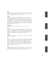
www.dell.com | support.dell.com Removing the Power Supply Small Form-Factor Computer 1 2 1 Release button 2 AC power connector 132 Power Supply
www.dell.com | support.dell.com Removing the Power Supply Small Form-Factor Computer 1 2 1 Release button 2 AC power connector 132 Power Supply
Service Manual
Page 133
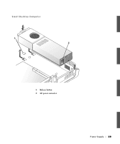
Small Desktop Computer 1 2 1 Release button 2 AC power connector Power Supply 133
Small Desktop Computer 1 2 1 Release button 2 AC power connector Power Supply 133


