Dell OptiPlex GX240 Support Question
Dell OptiPlex GX240 Support Question
Find answers below for this question about Dell OptiPlex GX240.Need a Dell OptiPlex GX240 manual? We have 3 online manuals for this item!
Question posted by chriscit on August 23rd, 2014
How Do I Check If My Dell Optiplex Gx240 Power Supply Is Bad
The person who posted this question about this Dell product did not include a detailed explanation. Please use the "Request More Information" button to the right if more details would help you to answer this question.
Current Answers
Related Dell OptiPlex GX240 Manual Pages
User's Guide - Page 6
... Replacing the Battery 148
4 Stand
Removing the Computer Stand 152 Attaching the Computer Stand 153
5 Technical Specifications
6 Solving Problems
Finding Solutions 164 Using the Dell OptiPlex ResourceCD 165 Power Problems 166 Video and Monitor Problems 166 Sound and Speaker Problems 168 Printer Problems 169
4 Contents Hard Drives 111 Detaching Hard Drive Cables 112...
User's Guide - Page 12

... electrical outlet.
• When you use a surge suppressor, line conditioner, or uninterruptible power supply (UPS).
• Ensure that nothing rests on your computer's cables and that the ...not spill food or liquids on your computer, and then from the network jack. www.dell.com | support.dell.com
CAUTION: Safety Instructions (continued)
• To avoid shorting out your computer when ...
User's Guide - Page 34
... 9
7 8
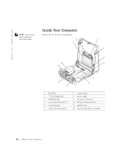
1 hard drive 2 3.5-inch floppy drive 3 CD/DVD drive 4 cover release buttons (2) 5 internal speaker 6 chassis intrusion switch
7 system board 8 power supply 9 AC power connector 10 I/O ports and connectors 11 padlock ring 12 heat sink and blower assembly
32 About Yo ur Computer www.dell.com | support.dell.com
NOTE: User service access points are colorcoded green.
User's Guide - Page 35

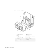
Small Desktop Computer
14
1
13
2
12 3
11
4
10
9 8 7
5 6
1 cover release buttons (2) 2 hard drive 3 internal speaker 4 chassis intrusion switch 5 expansion-card cage 6 power supply 7 expansion-card slots
8 AC power connector 9 padlock ring 10 I/O ports and connectors 11 heat sink and blower assembly 12 system board 13 3.5-inch floppy drive 14 CD/DVD drive
A bout Yo ur Computer 33
User's Guide - Page 36
www.dell.com | support.dell.com
Small Mini-Tower Computer
13
1
2 12
11 10
3
9 4
8
5 7
6
1 cover release buttons (2) 2 hard drive 3 internal speaker 4 chassis intrusion switch 5 system board 6 expansion-card slots 7 I/O ports and connectors
8 AC power connector 9 padlock ring 10 microprocessor and airflow shroud 11 power supply 12 3.5-inch floppy drive 13 CD/DVD drive
34 About Yo...
User's Guide - Page 162

www.dell.com | support.dell.com
Diagnostic lights
Standby power light Power DC power supply:
Wattage
Heat dissipation
Voltage
Backup battery Physical Small form-factor computer:
Height Width Depth Weight Small desktop computer: Height Width Depth Weight Small mini-tower computer: Height
four yellow and/or green lights on back of computer (see "I/O Panel-Small FormFactor, Desktop, and Mini...
User's Guide - Page 168

... computer and devices, and disconnect them from the Topic pull-down menu. Power Problems
Basic Checks:
• Test the electrical outlet: ensure that the electrical outlet is working by testing it . 3 Make sure the power cable is resolved. Yes. www.dell.com | support.dell.com
2 Click the appropriate driver and follow the instructions to the...
User's Guide - Page 180
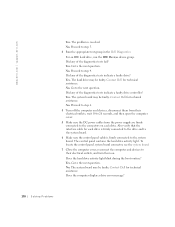
...4. The system board may be faulty. Go to the next question. No. Contact Dell for technical assistance. Contact Dell for each drive. The hard drive may be faulty. Did any of the diagnostics tests...to 20 seconds, and then open the computer cover. 5 Make sure the DC power cables from the power supply are firmly connected to their electrical outlets, and turn them on each drive is firmly...
User's Guide - Page 187
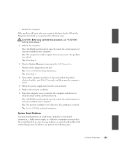
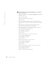
...Dell for technical assistance. Go to step 3. 3 Turn off the computer and devices, disconnect them from their electrical outlets, wait 10 to 20 seconds, and then open the computer cover. 4 Rotate the power supply away from a defective system board component, a faulty power supply...If the problem still exists after you complete the basic checks, fill out the Diagnostic Checklist as you perform the ...
User's Guide - Page 188
... 10 to 20 seconds, and then open the computer cover. 3 Make sure the power cables from the power supply are firmly connected to the connectors on the system board. 4 Close the computer cover..., reconnect the computer and devices to step 5. 5 Perform the procedure in the Dell Diagnostics. ...
User's Guide - Page 248

www.dell.com | support.dell.com
Polish Center for Testing and Certification Notice
The equipment should draw power from the power supply socket, which should be removed from a ...and PN-EN 55022: 1996.
246 Additional Infor mation To completely switch off the equipment, the power supply cable must be located near the equipment and easily accessible. A protection mark "B" confirms that works ...
User's Guide - Page 297

...of desktop, mobile, and server computers. WOL Wake-on Ring.
Technology that allows a computer chip to be installed or removed with current and emerging industry specifications, such as circuitry, power supply, ...as ACPI, CIM, SMBIOS, SNMP, and WBEM. WOR Wake-on LAN. A type of electrical power that allows a computer on a network to be remotely turned on or awakened from sleep mode....
Service Manual - Page 10
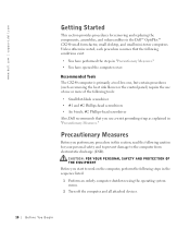
... #2 Phillips-head screwdrivers • An 8-inch, #2 Phillips-head screwdriver Also, Dell recommends that the following caution for removing and replacing the components, assemblies, and subassemblies...Recommended Tools
The GX240 computer is primarily a tool-less one, but certain procedures (such as explained in the Dell™ OptiPlex™ GX240 small form-factor, small desktop, and small ...
Service Manual - Page 20

...
3 4 5 6
10 9
7 8
1 Hard drive
7 System board
2 3.5-inch floppy drive
8 Power supply
3 CD/DVD drive
9 AC power connector
4 Cover release buttons (2) 10 I/O ports and connectors
5 Internal speaker
11 Padlock ring
6 Chassis intrusion switch 12 Heat sink and blower assembly
20 Inside the Computer
www.dell.com | support.dell.com
NOTE: User service access points are colorcoded green.
Service Manual - Page 21

Small Desktop Computer
14
1
13
2
12
11
3
4
10
9 8 7
5 6
1 Cover release buttons (2) 8 AC power connector
2 Hard drive
9 Padlock ring
3 Internal speaker
10 I/O ports and connectors
4 Chassis intrusion switch 11 Heat sink and blower assembly
5 Expansion-card cage
12 System board
6 Power supply
13 3.5-inch floppy drive
7 Expansion-card slots
14 CD/DVD drive
Inside the Computer...
Service Manual - Page 22

www.dell.com | support.dell.com
Small Mini-Tower Computer
13
1
2 12
11 10
3
9 4
8
5 7
6
1 Cover release buttons (2) 2 Hard drive 3 Internal speaker 4 Chassis intrusion switch 5 System board 6 Expansion-card slots 7 I/O ports and connectors
8 AC power connector 9 Padlock ring 10 Microprocessor and airflow shroud 11 Power supply 12 3.5-inch floppy drive 13 CD/DVD drive
22 Inside the...
Service Manual - Page 72

...dell.com | support.dell.com
1 Power cable 2 Audio cable 3 Data cable 4 Drive connector If your computer came with an IDE CD drive, use the IDE interface cable provided in the drive kit. 3 If you are installing a drive that has its own controller card, install the controller card in an expansion slot. 4 Check...
1 Disconnect the power cable and hard-drive cable from the drive.
72 D r i v e s
Service Manual - Page 131

SECTION 14
Power Supply
Removing the Power Supply Replacing the Power Supply
www.dell.com | support.dell.com
Service Manual - Page 132

www.dell.com | support.dell.com
Removing the Power Supply
Small Form-Factor Computer 1 2
1 Release button 2 AC power connector
132 Power Supply
Service Manual - Page 134

... small desktop computer, remove the expansion-card cage and remove the power cables from the clips while simultaneously pulling on the release button.
6 Slide the power supply toward the front of the computer approximately 1 inch. www.dell.com | support.dell.com
Small Mini-Tower Computer
134 Power Supply
1 Disconnect the AC power cable from the back of the power supply.
2 Disconnect...
Similar Questions

Can I Put A Secondary Hard Drive In Dell Optiplex Gx240 Desktop Directions
(Posted by rtbil 9 years ago)


Dell Optiplex 790 Power Supply Failure
When pushing the power button on the unit nothing happens. Is this probably the power supply.
When pushing the power button on the unit nothing happens. Is this probably the power supply.
(Posted by frankcurtiss 10 years ago)

