User Guide
Page 3
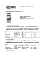
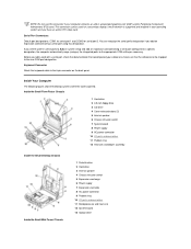
... 2 Headphone connector 3 Hard drive access indicator 4 Power button 5 Power indicator Front View of the Small Desktop System Front View of the Small Mini-Tower System 1 Front-panel door 2 Power button 3 Power indicator 4 Removable optical drive front panel 5 Removable diskette drive front panel 6 Diskette drive access...it or accidentally knock it off its hinges, it snaps back in place. fBack to Contents Page About Your Computer: Dell™ OptiPlex™ GX150 System User's Guide Front View Back View Inside Your Computer Front View The following figures show the controls, indicators, and...
... 2 Headphone connector 3 Hard drive access indicator 4 Power button 5 Power indicator Front View of the Small Desktop System Front View of the Small Mini-Tower System 1 Front-panel door 2 Power button 3 Power indicator 4 Removable optical drive front panel 5 Removable diskette drive front panel 6 Diskette drive access...it or accidentally knock it off its hinges, it snaps back in place. fBack to Contents Page About Your Computer: Dell™ OptiPlex™ GX150 System User's Guide Front View Back View Inside Your Computer Front View The following figures show the controls, indicators, and...
User Guide
Page 4
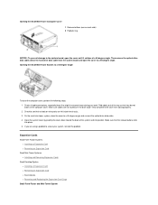
... result in data loss. NOTICE: To turn off System Turned Off Boots and system turns on Boots and system turns on the Small Mini-Tower System 1 Front-panel door, with two breakaway hinges 2 Headphone connector 3 USB connectors (2) (do not use these front connectors for Microsoft ...Results System in the following table. Power Button Behavior Under Microsoft Windows 98, Windows 98 SE, Windows 2000, and Windows XP (With Dell AutoShutdown Loaded) Action System Turned On and ACPI Disabled Press power button System turns off immediately Hold power button for the Windows 98,...
... result in data loss. NOTICE: To turn off System Turned Off Boots and system turns on Boots and system turns on the Small Mini-Tower System 1 Front-panel door, with two breakaway hinges 2 Headphone connector 3 USB connectors (2) (do not use these front connectors for Microsoft ...Results System in the following table. Power Button Behavior Under Microsoft Windows 98, Windows 98 SE, Windows 2000, and Windows XP (With Dell AutoShutdown Loaded) Action System Turned On and ACPI Disabled Press power button System turns off immediately Hold power button for the Windows 98,...
User Guide
Page 6
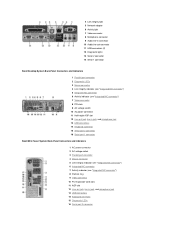
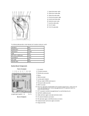
... Line-out jack, line-in jack, and microphone jack 13 USB connectors 14 Keyboard connector 15 Serial port 2 connector 16 Serial port 1 connector Small Mini-Tower System Back-Panel Connectors and Indicators 1 AC power connector 2 AC voltage switch 3 Parallel port connector 4 Mouse connector 5 Link integrity indicator (see "Integrated NIC connector") 6 Integrated...
... Line-out jack, line-in jack, and microphone jack 13 USB connectors 14 Keyboard connector 15 Serial port 2 connector 16 Serial port 1 connector Small Mini-Tower System Back-Panel Connectors and Indicators 1 AC power connector 2 AC voltage switch 3 Parallel port connector 4 Mouse connector 5 Link integrity indicator (see "Integrated NIC connector") 6 Integrated...
User Guide
Page 8
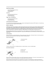
... 9 AC power connector 10 I/O ports and connectors 11 Padlock ring 12 Heat sink and blower assembly Inside the Small Desktop Chassis Inside the Small Mini-Tower Chassis 1 Diskette drive 2 Hard drive 3 Internal speaker 4 Chassis intrusion switch 5 Expansion-card cage 6 Power supply 7 Expansion-card slots 8 AC power connector 9 Padlock ring 10 I/O ports...
... 9 AC power connector 10 I/O ports and connectors 11 Padlock ring 12 Heat sink and blower assembly Inside the Small Desktop Chassis Inside the Small Mini-Tower Chassis 1 Diskette drive 2 Hard drive 3 Internal speaker 4 Chassis intrusion switch 5 Expansion-card cage 6 Power supply 7 Expansion-card slots 8 AC power connector 9 Padlock ring 10 I/O ports...
User Guide
Page 10
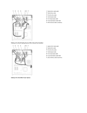
1 Optical drive audio cable 2 Optical drive cable 3 Diskette drive cable 4 Control panel cable 5 Front input/output cable 6 Front input/output audio cable 7 EIDE interface cable (hard drive) Cabling in the Small Desktop System With a Sound Card Installed 1 Optical drive audio cable 2 Optical drive cable 3 Diskette drive cable 4 Control panel cable 5 Front input/output cable 6 Front input/output audio cable 7 EIDE interface cable (hard drive) Cabling in the Small Mini-Tower System
1 Optical drive audio cable 2 Optical drive cable 3 Diskette drive cable 4 Control panel cable 5 Front input/output cable 6 Front input/output audio cable 7 EIDE interface cable (hard drive) Cabling in the Small Desktop System With a Sound Card Installed 1 Optical drive audio cable 2 Optical drive cable 3 Diskette drive cable 4 Control panel cable 5 Front input/output cable 6 Front input/output audio cable 7 EIDE interface cable (hard drive) Cabling in the Small Mini-Tower System
User Guide
Page 11
... small form-factor chassis, used as the riser in the small desktop chassis, and can be populated with PCI expansion card in the small mini-tower chassis) 11 PCI 1 connector (not able to be populated on the small desktop chassis) 12 AGP/GPA (AIMM) connector 13 Video connector (upper) and audio...
... small form-factor chassis, used as the riser in the small desktop chassis, and can be populated with PCI expansion card in the small mini-tower chassis) 11 PCI 1 connector (not able to be populated on the small desktop chassis) 12 AGP/GPA (AIMM) connector 13 Video connector (upper) and audio...
User Guide
Page 47
...to devices according to pin 1 of pin 1 on the drive. For the location of the drive's interface connector. the small mini-tower system supports two EIDE hard drives. Your drive's power input connector (to press in the following connector. When you disconnect an interface ...Drives Hard Drives l Small Form-Factor Desktop System l Small Desktop System l Small Mini-Tower System Floppy, Tape, or CD-ROM Drives l Small Form-Factor Desktop System l Small Desktop System l Small Mini-Tower System General Information About Hard Drives The small form-factor and small desktop systems support ...
...to devices according to pin 1 of pin 1 on the drive. For the location of the drive's interface connector. the small mini-tower system supports two EIDE hard drives. Your drive's power input connector (to press in the following connector. When you disconnect an interface ...Drives Hard Drives l Small Form-Factor Desktop System l Small Desktop System l Small Mini-Tower System Floppy, Tape, or CD-ROM Drives l Small Form-Factor Desktop System l Small Desktop System l Small Mini-Tower System General Information About Hard Drives The small form-factor and small desktop systems support ...
User Guide
Page 51
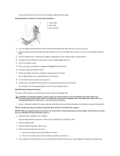
...want to keep, be sure to make a backup of your files before you begin this procedure. Attaching Hard Drive Cables in a small mini-tower system, perform the following steps. Enter system setup, and update the appropriate Primary Drive option (0 or 1). 16. Partition and logically format ...Small Desktop System 1 Power cable 2 EIDE cable 3 IDE1 connector 10. For You and Your Computer." 1. NOTICE: Ground yourself by running the Dell Diagnostics. 19. Instead, set it is the primary drive, insert a bootable floppy into place. 12. Check the documentation for the drive to step 8. 5....
...want to keep, be sure to make a backup of your files before you begin this procedure. Attaching Hard Drive Cables in a small mini-tower system, perform the following steps. Enter system setup, and update the appropriate Primary Drive option (0 or 1). 16. Partition and logically format ...Small Desktop System 1 Power cable 2 EIDE cable 3 IDE1 connector 10. For You and Your Computer." 1. NOTICE: Ground yourself by running the Dell Diagnostics. 19. Instead, set it is the primary drive, insert a bootable floppy into place. 12. Check the documentation for the drive to step 8. 5....
User Guide
Page 52
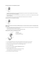
... 17. Test the hard drive by gently sliding the bracket into drive A. 14. Installing a Hard Drive in the chassis by running the Dell Diagnostics. Check all connectors to the IDE1 connector on the back of the EIDE cable to be certain that are attached. Close the computer ... system board. 12. Partition and logically format your drive before you are properly cabled and firmly seated. Removing the Hard Drive in the Small Mini-Tower System 1 EIDE cable 2 Drive power connector 3 System board IDE1 connector 11. If necessary, attach the bracket rails to your upgrade kit. 8....
... 17. Test the hard drive by gently sliding the bracket into drive A. 14. Installing a Hard Drive in the chassis by running the Dell Diagnostics. Check all connectors to the IDE1 connector on the back of the EIDE cable to be certain that are attached. Close the computer ... system board. 12. Partition and logically format your drive before you are properly cabled and firmly seated. Removing the Hard Drive in the Small Mini-Tower System 1 EIDE cable 2 Drive power connector 3 System board IDE1 connector 11. If necessary, attach the bracket rails to your upgrade kit. 8....
User Guide
Page 59
... Unpack the drive and prepare it for your configuration. 2. For instructions on the drive. Removing the 3.5-Inch Floppy Drive in a small mini-tower system, perform the following steps. If the new floppy drive does not have the bracket rails attached, remove the old drive from the panel... surface on installing and using the tape drive software. 14. After you are installing an EIDE drive, configure the drive for cable select by Dell come with the drive for your computer system. CAUTION: To avoid the possibility of the drive bay to the drive. 4. Change any peripherals,...
... Unpack the drive and prepare it for your configuration. 2. For instructions on the drive. Removing the 3.5-Inch Floppy Drive in a small mini-tower system, perform the following steps. If the new floppy drive does not have the bracket rails attached, remove the old drive from the panel... surface on installing and using the tape drive software. 14. After you are installing an EIDE drive, configure the drive for cable select by Dell come with the drive for your computer system. CAUTION: To avoid the possibility of the drive bay to the drive. 4. Change any peripherals,...

User Guide
Page 60
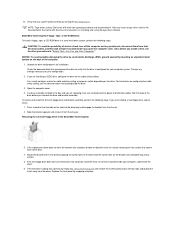
... the appropriate interface cable to the power input connector on the back of the drive. Installing the 3.5 Inch Drive in the Small Mini-Tower System Connect the power cable to the interface connector on the sides of the drive bay to step 4. a. Press inward on the two... installing a new drive, skip to disengage the bracket from the chassis. Removing the 5.25-Inch Drive in the Small Mini-Tower System 8. Attaching Floppy Drive Cables in the Small Mini-Tower System 1 DC power cable 2 Floppy drive connector 3 System board floppy connector (DSKT) To remove and install a 5.25-...
... the appropriate interface cable to the power input connector on the back of the drive. Installing the 3.5 Inch Drive in the Small Mini-Tower System Connect the power cable to the interface connector on the sides of the drive bay to step 4. a. Press inward on the two... installing a new drive, skip to disengage the bracket from the chassis. Removing the 5.25-Inch Drive in the Small Mini-Tower System 8. Attaching Floppy Drive Cables in the Small Mini-Tower System 1 DC power cable 2 Floppy drive connector 3 System board floppy connector (DSKT) To remove and install a 5.25-...
User Guide
Page 61
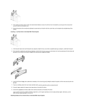
... tightening all four screws. If you are installing a drive that has its own controller card, install the controller card in the Small Mini-Tower System Attaching Cables to the 5.25-Inch Drive in an expansion slot. 8. Connect the appropriate interface cable to the power input connector on ... panel by removing the four screws that is going into place. 6. Install the 5.25-inch floppy drive and bracket assembly in the Small Mini-Tower System 4. Attach the bracket to the bracket rails. 3. 2. If the replacement drive does not have the bracket rails attached, install the extra ...
... tightening all four screws. If you are installing a drive that has its own controller card, install the controller card in the Small Mini-Tower System Attaching Cables to the 5.25-Inch Drive in an expansion slot. 8. Connect the appropriate interface cable to the power input connector on ... panel by removing the four screws that is going into place. 6. Install the 5.25-inch floppy drive and bracket assembly in the Small Mini-Tower System 4. Attach the bracket to the bracket rails. 3. 2. If the replacement drive does not have the bracket rails attached, install the extra ...
User Guide
Page 76
...RAM test group in its connector. Did any of the expansion cards that you have a mini tower chassis, replace the AGP card brace. 6. Yes. Proceed to step 11. 11. Press . 2. Contact Dell for technical assistance. Make sure each expansion card is faulty and needs to a drive controller card...are loose, reseat them . No. Repeat steps 11 and 12 with software or other hardware, or a faulty expansion card. If you have a mini tower chassis, remove the AGP card brace. 3. Recover From a Program That Is Not Responding 1. You may have a faulty expansion card. Turn off the ...
...RAM test group in its connector. Did any of the expansion cards that you have a mini tower chassis, replace the AGP card brace. 6. Yes. Proceed to step 11. 11. Press . 2. Contact Dell for technical assistance. Make sure each expansion card is faulty and needs to a drive controller card...are loose, reseat them . No. Repeat steps 11 and 12 with software or other hardware, or a faulty expansion card. If you have a mini tower chassis, remove the AGP card brace. 3. Recover From a Program That Is Not Responding 1. You may have a faulty expansion card. Turn off the ...
User Guide
Page 77
... outlets, wait at least 5 seconds, and then open the computer cover. 7. Run the System Board Devices test group in the Dell Diagnostics. Turn off the computer and peripherals, disconnect them from their electrical outlets, and turn them on . 5. Yes. No. ...Dell for technical assistance. Turn off the computer and peripherals, disconnect them from their electrical outlets, and turn them on . 10. Restart a Computer That Is Not Responding 1. Repairing a Dropped or Damaged Computer CAUTION: Before you perform the following steps: 1. Does the system have a micro tower...
... outlets, wait at least 5 seconds, and then open the computer cover. 7. Run the System Board Devices test group in the Dell Diagnostics. Turn off the computer and peripherals, disconnect them from their electrical outlets, and turn them on . 5. Yes. No. ...Dell for technical assistance. Turn off the computer and peripherals, disconnect them from their electrical outlets, and turn them on . 10. Restart a Computer That Is Not Responding 1. Repairing a Dropped or Damaged Computer CAUTION: Before you perform the following steps: 1. Does the system have a micro tower...

User Guide
Page 80
... hardware without additional equipment and without indicating any problems, you begin. NOTE: Write down and restart the computer. 2. Insert the Dell OptiPlex ResourceCD into the CD drive. 5. Features The diagnostic test groups features allow you experience a problem with other computers may cause incorrect... extensive tests on one is online. If you will need when talking to run the Dell Diagnostics before you can have a micro tower chassis, remove the AGP card brace. 3. Contact Dell for technical assistance. NOTICE: Only use the CD drive as ports. The problem is ...
... hardware without additional equipment and without indicating any problems, you begin. NOTE: Write down and restart the computer. 2. Insert the Dell OptiPlex ResourceCD into the CD drive. 5. Features The diagnostic test groups features allow you experience a problem with other computers may cause incorrect... extensive tests on one is online. If you will need when talking to run the Dell Diagnostics before you can have a micro tower chassis, remove the AGP card brace. 3. Contact Dell for technical assistance. NOTICE: Only use the CD drive as ports. The problem is ...

User Guide
Page 101
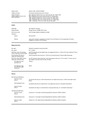
...) 2.0s- full-height cards [up to 22.9 cm or 9 inches] for small form-factor and small desktop systems; Back to Contents Page Technical Specifications: Dell™ OptiPlex™ GX150 System User's Guide Processor Memory System Information Graphics (Optional) and Video Audio Expansion Bus Drives Ports Key Combinations Controls and Indicators Power Physical Environmental... Video Memory Technology (DVMT) with optional 4-MB Graphics Performance Accelerator (GPA), or a 4X AGP card can be supported (low profile cards for the small mini-tower system)
...) 2.0s- full-height cards [up to 22.9 cm or 9 inches] for small form-factor and small desktop systems; Back to Contents Page Technical Specifications: Dell™ OptiPlex™ GX150 System User's Guide Processor Memory System Information Graphics (Optional) and Video Audio Expansion Bus Drives Ports Key Combinations Controls and Indicators Power Physical Environmental... Video Memory Technology (DVMT) with optional 4-MB Graphics Performance Accelerator (GPA), or a 4X AGP card can be supported (low profile cards for the small mini-tower system)
User Guide
Page 102
... 32 bits Drives Externally accessible bays: Small form-factor chassis Small desktop chassis Small mini-tower chassis Internally accessible bays: Small form-factor chassis Small desktop chassis Small mini-tower chassis one bay for a 1-inch-high enhanced integrated drive electronics (EIDE) hard drive ... Bus speed Small form-factor (SF) desktop chassis expansion-card connector Small desktop (SD) chassis expansion-card connectors: Small mini-tower (SMT) chassis expansion-card connectors: PCI expansion-card connector size Peripheral Component Interconnect (PCI) PCI-33 MHz one optical drive ...
... 32 bits Drives Externally accessible bays: Small form-factor chassis Small desktop chassis Small mini-tower chassis Internally accessible bays: Small form-factor chassis Small desktop chassis Small mini-tower chassis one bay for a 1-inch-high enhanced integrated drive electronics (EIDE) hard drive ... Bus speed Small form-factor (SF) desktop chassis expansion-card connector Small desktop (SD) chassis expansion-card connectors: Small mini-tower (SMT) chassis expansion-card connectors: PCI expansion-card connector size Peripheral Component Interconnect (PCI) PCI-33 MHz one optical drive ...

User Guide
Page 104
...: Wattage Heat dissipation Voltage Backup battery Physical Small form-factor chassis: Height Width Depth Weight Small desktop chassis: Height Width Depth Weight Small mini-tower chassis: Height Width Depth Weight Environmental Temperature: Operating Storage Relative humidity Maximum vibration: Operating Storage Maximum shock: Operating small form-factor chassis: 100...: 200 W small form-factor chassis: 455 BTU/hr (average) small desktop chassis: 500 BTU/hr (average) small mini-tower chassis: 910 BTU/hr (average) 90 to 135 volts (V) at 60 Hz; 180 to 265 V at 50 Hz 3-V CR2032 lithium coin cell 9.0...
...: Wattage Heat dissipation Voltage Backup battery Physical Small form-factor chassis: Height Width Depth Weight Small desktop chassis: Height Width Depth Weight Small mini-tower chassis: Height Width Depth Weight Environmental Temperature: Operating Storage Relative humidity Maximum vibration: Operating Storage Maximum shock: Operating small form-factor chassis: 100...: 200 W small form-factor chassis: 455 BTU/hr (average) small desktop chassis: 500 BTU/hr (average) small mini-tower chassis: 910 BTU/hr (average) 90 to 135 volts (V) at 60 Hz; 180 to 265 V at 50 Hz 3-V CR2032 lithium coin cell 9.0...
User Guide
Page 108
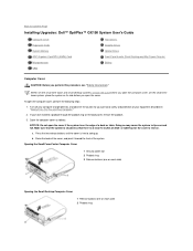
.... a. Turn off your computer and peripherals, and observe the caution for the cover to Contents Page Installing Upgrades: Dell™ OptiPlex™ GX150 System User's Guide Computer Cover Expansion Cards System Memory AGP Graphics Card/GPA (AIMM) Card Microprocessor VRM Hard Drives ...Diskette Drives Optical Drives Front-Panel Inserts (Small Desktop and Mini-Tower Chassis) Battery Computer Cover CAUTION: Before you open ...
.... a. Turn off your computer and peripherals, and observe the caution for the cover to Contents Page Installing Upgrades: Dell™ OptiPlex™ GX150 System User's Guide Computer Cover Expansion Cards System Memory AGP Graphics Card/GPA (AIMM) Card Microprocessor VRM Hard Drives ...Diskette Drives Optical Drives Front-Panel Inserts (Small Desktop and Mini-Tower Chassis) Battery Computer Cover CAUTION: Before you open ...
User Guide
Page 109
...during your system, reinstall the padlock. Expansion Cards Small Form-Factor Systems l Installing an Expansion Card l Removing an Expansion Card Small Mini-Tower Systems l Installing and Removing Expansion Cards Small Desktop System l Installing an Expansion Card l Removing an Expansion Card l Riser Boards l ...Removing and Replacing the Expansion-Card Cage Small Form-Factor and Mini-Tower System Make sure cables are using a padlock to a 45-degree angle and connect the optical drive data cable. 4. Check all cable...
...during your system, reinstall the padlock. Expansion Cards Small Form-Factor Systems l Installing an Expansion Card l Removing an Expansion Card Small Mini-Tower Systems l Installing and Removing Expansion Cards Small Desktop System l Installing an Expansion Card l Removing an Expansion Card l Riser Boards l ...Removing and Replacing the Expansion-Card Cage Small Form-Factor and Mini-Tower System Make sure cables are using a padlock to a 45-degree angle and connect the optical drive data cable. 4. Check all cable...


