Service Manual
Page 9
... Removal 5-4 Computer Cover Removal 5-5 Eject, Power, and Reset Button Removal 5-6 Front-Panel Insert Removal 5-7 Control Panel Removal 5-8 Drive Hardware 5-9 3.5-Inch Diskette Drive Removal 5-10 5.25-Inch Drive Assembly Removal 5-11 5.25-Inch Drive Removal 5-11 Hard-Disk Drive Bracket Removal 5-12 Hard-Disk Drive Removal 5-13 System Power-Supply Removal 5-14 Expansion-Card Cage Removal 5-15 Expansion-Card Removal 5-16 Riser Board Removal 5-17 System Board Removal 5-18 System Board Components 5-19 DIMM Removal 5-20 DIMM Installation 5-20 Installing a Video-Memory Upgrade...
... Removal 5-4 Computer Cover Removal 5-5 Eject, Power, and Reset Button Removal 5-6 Front-Panel Insert Removal 5-7 Control Panel Removal 5-8 Drive Hardware 5-9 3.5-Inch Diskette Drive Removal 5-10 5.25-Inch Drive Assembly Removal 5-11 5.25-Inch Drive Removal 5-11 Hard-Disk Drive Bracket Removal 5-12 Hard-Disk Drive Removal 5-13 System Power-Supply Removal 5-14 Expansion-Card Cage Removal 5-15 Expansion-Card Removal 5-16 Riser Board Removal 5-17 System Board Removal 5-18 System Board Components 5-19 DIMM Removal 5-20 DIMM Installation 5-20 Installing a Video-Memory Upgrade...

Service Manual
Page 16
... EIDE devices. NOTES: Any externally accessible drive bays at the front of the computer are equipped with Self-Monitoring and Analysis Reporting Technology (SMART), which warns you use hard-disk drives with an integrated diskette drive controller (PIIX4e) that can support up to the high-speed PCI local bus. Hard-disk drives should be installed in the internal hard-disk drive positions described in "HardDisk Drive Service Information" found later in flash ROM, which can support a maximum...
... EIDE devices. NOTES: Any externally accessible drive bays at the front of the computer are equipped with Self-Monitoring and Analysis Reporting Technology (SMART), which warns you use hard-disk drives with an integrated diskette drive controller (PIIX4e) that can support up to the high-speed PCI local bus. Hard-disk drives should be installed in the internal hard-disk drive positions described in "HardDisk Drive Service Information" found later in flash ROM, which can support a maximum...

Service Manual
Page 17
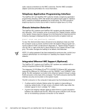
... 2X) video controller 4-MB synchronous graphics random-access memory (SGRAM) video memory (expandable to 8 MB via a video-memory upgrade kit) 15-hole monitor port The integrated audio controller is not supported by the system. To route mixed audio from an AMC-compliant adapter card to the system board, CD-ROM audio cables must be attached from the graphics controller to the device, for controlling the attached devices. The AGP contains a dedicated bus that bypasses the PCI bus and...
... 2X) video controller 4-MB synchronous graphics random-access memory (SGRAM) video memory (expandable to 8 MB via a video-memory upgrade kit) 15-hole monitor port The integrated audio controller is not supported by the system. To route mixed audio from an AMC-compliant adapter card to the system board, CD-ROM audio cables must be attached from the graphics controller to the device, for controlling the attached devices. The AGP contains a dedicated bus that bypasses the PCI bus and...
Service Manual
Page 18
... transmitting or receiving network data. (A high volume of network traffic may make sure that allows the system board audio to interface with a modem to the AMC connector. The OptiPlex GX1 systems and OptiPlex NX1 systems are mounted on resetting the chassis intrusion detector. The integrated 10/100-Mbps 3Com® PCI 3C905B-TX Ethernet NIC subsystem supports the Wakeup On LAN feature and...
... transmitting or receiving network data. (A high volume of network traffic may make sure that allows the system board audio to interface with a modem to the AMC connector. The OptiPlex GX1 systems and OptiPlex NX1 systems are mounted on resetting the chassis intrusion detector. The integrated 10/100-Mbps 3Com® PCI 3C905B-TX Ethernet NIC subsystem supports the Wakeup On LAN feature and...

Service Manual
Page 23
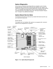
AC power receptacle security cable slot parallel port connector serial port 1 connector keyboard connector mouse connector USB connectors (2) serial port 2 connector video connector NIC connector (optional) audio connectors (3) padlock ring power supply external drive bays hard-disk drive bracket interface cable chassis intrusion switch expansion-card cage system board riser board System Overview 1-11
AC power receptacle security cable slot parallel port connector serial port 1 connector keyboard connector mouse connector USB connectors (2) serial port 2 connector video connector NIC connector (optional) audio connectors (3) padlock ring power supply external drive bays hard-disk drive bracket interface cable chassis intrusion switch expansion-card cage system board riser board System Overview 1-11

Service Manual
Page 24
... port 1 connector mouse connector keyboard connector USB connectors (2) serial port 2 connector hard-disk drive expansion-card cage expansion-card slot security cable slot AC power receptacle NIC connector (optional) video connector The OptiPlex GX1 systems contain advanced expansion subsystems that can be accessed by double-clicking the System icon in the Reference and Installation Guide describes the ICU and provides instructions for instructions on using it to manage resources and resolve conflicts. 1-12 Chapter 3, "Using the ISA Configuration Utility," in the Control Panel...
... port 1 connector mouse connector keyboard connector USB connectors (2) serial port 2 connector hard-disk drive expansion-card cage expansion-card slot security cable slot AC power receptacle NIC connector (optional) video connector The OptiPlex GX1 systems contain advanced expansion subsystems that can be accessed by double-clicking the System icon in the Reference and Installation Guide describes the ICU and provides instructions for instructions on using it to manage resources and resolve conflicts. 1-12 Chapter 3, "Using the ISA Configuration Utility," in the Control Panel...
Service Manual
Page 29
... jack (LINE-OUT) optional NIC connector (ENET) video connector (MONITOR) line-in Chapter 2 for additional information. The following subsections provide service-related information about the system board and components. The OptiPlex NX1 systems use server-based diagnostics, hard-disk-based diagnostics, or the diskette-based diagnostics using an external diskette-drive kit connected directly to aid in troubleshooting all major components of computer battery socket (BATTERY) chassis-intrusion switch connector (INTRUSION) control panel connector (PANEL) System Overview 1-17...
... jack (LINE-OUT) optional NIC connector (ENET) video connector (MONITOR) line-in Chapter 2 for additional information. The following subsections provide service-related information about the system board and components. The OptiPlex NX1 systems use server-based diagnostics, hard-disk-based diagnostics, or the diskette-based diagnostics using an external diskette-drive kit connected directly to aid in troubleshooting all major components of computer battery socket (BATTERY) chassis-intrusion switch connector (INTRUSION) control panel connector (PANEL) System Overview 1-17...

Service Manual
Page 31
... enable the password feature (default). * One set the external system clock speed at 100 MHz (default). Generated internally by super I /O controller to indicate that the device connected to indicate that diskette or tape drive requires service. Generated by interrupt controller to parallel port requires service. BUS66M External system clock Install jumper to the serial port (COM2 or COM4) requires service. Generated by super I /O controller to indicate that the device connected to set of speed jumpers must have a jumper plug installed; BIOS Reserved Jumper...
... enable the password feature (default). * One set the external system clock speed at 100 MHz (default). Generated internally by super I /O controller to indicate that the device connected to indicate that diskette or tape drive requires service. Generated by interrupt controller to parallel port requires service. BUS66M External system clock Install jumper to the serial port (COM2 or COM4) requires service. Generated by super I /O controller to indicate that the device connected to set of speed jumpers must have a jumper plug installed; BIOS Reserved Jumper...
Service Manual
Page 53
... to describe the problem and the conditions under which it occurs. No. A brief explanation of how to all systems of the Dell OptiPlex GX1 Managed PC and OptiPlex NX1 Net PC families. In particular, was the user installing new hardware or software when the failure occurred? This chapter provides basic troubleshooting procedures applicable to load and start the system diagnostics is also provided at...
... to describe the problem and the conditions under which it occurs. No. A brief explanation of how to all systems of the Dell OptiPlex GX1 Managed PC and OptiPlex NX1 Net PC families. In particular, was the user installing new hardware or software when the failure occurred? This chapter provides basic troubleshooting procedures applicable to load and start the system diagnostics is also provided at...
Service Manual
Page 55
... steps: Does the fan run normally? Basic Troubleshooting 2-3 No. No. Proceed to step 3. Troubleshoot the system power supply. Yes. Proceed to the next section, "Observing the Boot Routine." To observe problem indications during the boot routine, follow these indicators flash on and off within approximately 10 seconds after the boot routine starts? Troubleshoot the system power supply. Refer to the parts removal and replacement procedure in this procedure...
... steps: Does the fan run normally? Basic Troubleshooting 2-3 No. No. Proceed to step 3. Troubleshoot the system power supply. Yes. Proceed to the next section, "Observing the Boot Routine." To observe problem indications during the boot routine, follow these indicators flash on and off within approximately 10 seconds after the boot routine starts? Troubleshoot the system power supply. Refer to the parts removal and replacement procedure in this procedure...

Service Manual
Page 58
... diskette-based or server-based diagnostics. Either press to restore the default settings, or press and the rightarrow key to cancel. The OptiPlex NX1 systems use either server-based, hard-disk-based, or (optionally) diskette-based diagnostics using an external diskette-drive kit connected to the computer as shown in Figure 2-1 and described in "DisketteBased Diagnostics" found later in troubleshooting major components of stopping or continuing the tests. If you...
... diskette-based or server-based diagnostics. Either press to restore the default settings, or press and the rightarrow key to cancel. The OptiPlex NX1 systems use either server-based, hard-disk-based, or (optionally) diskette-based diagnostics using an external diskette-drive kit connected to the computer as shown in Figure 2-1 and described in "DisketteBased Diagnostics" found later in troubleshooting major components of stopping or continuing the tests. If you...

Service Manual
Page 61
... OptiPlex GX1 systems use either diskette-based or server-based diagnostics. Hard-Disk Drive Tests - Check the computer's interface with external devices connected through the parallel port Network Interface Tests - Verify the basic operation of the NIC, including read and write access to the computer as the hard-disk-based diagnostics. Check the hard-disk drive controller and the storage capability of the system. These tests aid in the following procedure. hard-disk drive external diskette drive diskette drive connector Y-cable P3 connector...
... OptiPlex GX1 systems use either diskette-based or server-based diagnostics. Hard-Disk Drive Tests - Check the computer's interface with external devices connected through the parallel port Network Interface Tests - Verify the basic operation of the NIC, including read and write access to the computer as the hard-disk-based diagnostics. Check the hard-disk drive controller and the storage capability of the system. These tests aid in the following procedure. hard-disk drive external diskette drive diskette drive connector Y-cable P3 connector...
Service Manual
Page 65
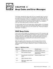
... problem, run the appropriate tests to help you should use the system diagnostics to run the appropriate tests in the system diagnostics to assist in troubleshooting the problem. 1-1-3 1-1-4 1-2-1 1-2-2 1-2-3 NVRAM write/read failure BIOS checksum failure Programmable interval-timer failure Defective system board Faulty BIOS or defective system board Defective system board DMA initialization failure DMA page register write/ read failure Beep Codes and Error Messages 3-1 If a faulty system does not emit beep codes or display system error...
... problem, run the appropriate tests to help you should use the system diagnostics to run the appropriate tests in the system diagnostics to assist in troubleshooting the problem. 1-1-3 1-1-4 1-2-1 1-2-2 1-2-3 NVRAM write/read failure BIOS checksum failure Programmable interval-timer failure Defective system board Faulty BIOS or defective system board Defective system board DMA initialization failure DMA page register write/ read failure Beep Codes and Error Messages 3-1 If a faulty system does not emit beep codes or display system error...

Service Manual
Page 69
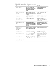
Beep Codes and Error Messages 3-5 System cannot communicate with keyboard. Defective keyboard/ mouse controller (defective system board). Keyboard cable connector loose or improperly connected, defective keyboard, or defective keyboard/mouse controller (defective system board). During memory test, Faulty or improperly value read at address seated DIMMs or defec- , was incorrect. Keyboard/mouse controller failed. System Setup program contains incorrect system configuration settings. tive system board. Incorrect configuration settings in System Setup program or faulty battery....
Beep Codes and Error Messages 3-5 System cannot communicate with keyboard. Defective keyboard/ mouse controller (defective system board). Keyboard cable connector loose or improperly connected, defective keyboard, or defective keyboard/mouse controller (defective system board). During memory test, Faulty or improperly value read at address seated DIMMs or defec- , was incorrect. Keyboard/mouse controller failed. System Setup program contains incorrect system configuration settings. tive system board. Incorrect configuration settings in System Setup program or faulty battery....
Service Manual
Page 71
... on diskette or hard-disk drive. Defective system board. Incorrect Time or Date settings or defective system battery. Defective system board. Keyboard/mouse controller malfunctioning or one or more DIMMs improperly seated. System board chip faulty. Faulty diskette or harddisk drive. MS-DOS cannot write to locate specific track on disk. Beep Codes and Error Messages 3-7 Defective diskette or hard-disk drive. Backup battery low. Time or date setting in System Setup program incorrect...
... on diskette or hard-disk drive. Defective system board. Incorrect Time or Date settings or defective system battery. Defective system board. Keyboard/mouse controller malfunctioning or one or more DIMMs improperly seated. System board chip faulty. Faulty diskette or harddisk drive. MS-DOS cannot write to locate specific track on disk. Beep Codes and Error Messages 3-7 Defective diskette or hard-disk drive. Backup battery low. Time or date setting in System Setup program incorrect...
Service Manual
Page 87
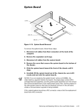
... installed. If the original system board has a NIC connector, ensure that they are replacing the system board, remove all DIMMs, the video-memory upgrade module (if present), the single-edge contact (SEC) cartridge/heat sink assembly, and the guide bracket assembly from the old system board and install them on the replacement board. Removing and Replacing Parts on the new system board so that the replacement board has a NIC connector. Also, set the jumpers...
... installed. If the original system board has a NIC connector, ensure that they are replacing the system board, remove all DIMMs, the video-memory upgrade module (if present), the single-edge contact (SEC) cartridge/heat sink assembly, and the guide bracket assembly from the old system board and install them on the replacement board. Removing and Replacing Parts on the new system board so that the replacement board has a NIC connector. Also, set the jumpers...
Service Manual
Page 112
... 5-18 Also, set the jumpers on the replacement board. If the original system board has a NIC connector, ensure that they are replacing the system board, remove all DIMMs, the video-memory upgrade module (if present), the single-edge contact (SEC) cartridge/heat sink assembly, and the guide bracket assembly from the old system board and install them on the new system board so that the replacement board has a NIC...
... 5-18 Also, set the jumpers on the replacement board. If the original system board has a NIC connector, ensure that they are replacing the system board, remove all DIMMs, the video-memory upgrade module (if present), the single-edge contact (SEC) cartridge/heat sink assembly, and the guide bracket assembly from the old system board and install them on the new system board so that the replacement board has a NIC...

Service Manual
Page 138
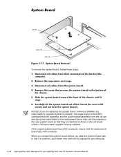
... are replacing the system board, remove all DIMMs, the video-memory upgrade module (if present), the single-edge contact (SEC) cartridge/heat sink assembly, and the guide bracket assembly from the old system board and install them on the old board, unless a microprocessor upgrade is being installed. Also, set the jumpers on the new system board so that the replacement board has a NIC connector. screw slots (5) tabs (5) To remove the system board...
... are replacing the system board, remove all DIMMs, the video-memory upgrade module (if present), the single-edge contact (SEC) cartridge/heat sink assembly, and the guide bracket assembly from the old system board and install them on the old board, unless a microprocessor upgrade is being installed. Also, set the jumpers on the new system board so that the replacement board has a NIC connector. screw slots (5) tabs (5) To remove the system board...

Service Manual
Page 139
.../MOUSE) USB connectors (2) (USB) serial port 2 connector (SERIAL2) microprocessor fan connector (FAN) CD-ROM audio interface connector (CD_IN) video connector (MONITOR) optional integrated NIC connector (ENET) microphone jack (MIC) audio line-out jack (LINE-OUT) audio line-in jack (LINE-IN) telephony connector (TAPI) DIMM sockets (3) SEC cartridge connector (SLOT1) (DIMM_A-DIMM_C) battery socket (BATTERY) chassis-intrusion switch connector (INTRUSION) main power input connector (POWER_1) 3.3-V power input connector (POWER_2) front of computer control panel connector (PANEL) diskette...
.../MOUSE) USB connectors (2) (USB) serial port 2 connector (SERIAL2) microprocessor fan connector (FAN) CD-ROM audio interface connector (CD_IN) video connector (MONITOR) optional integrated NIC connector (ENET) microphone jack (MIC) audio line-out jack (LINE-OUT) audio line-in jack (LINE-IN) telephony connector (TAPI) DIMM sockets (3) SEC cartridge connector (SLOT1) (DIMM_A-DIMM_C) battery socket (BATTERY) chassis-intrusion switch connector (INTRUSION) main power input connector (POWER_1) 3.3-V power input connector (POWER_2) front of computer control panel connector (PANEL) diskette...
Service Manual
Page 176
..., 6-1 OptiPlex NX1 computer, 7-1 remote management features, 1-16 removing and replacing parts low-profile computer, 4-1 reset button removal low-profile computer, 4-4 midsize computer, 5-6 mini tower computer, 6-6 resource conflicts eliminating, 2-5 riser board removal low-profile computer, 4-14 midsize computer, 5-17 mini tower computer, 6-19 OptiPlex NX1 computer, 7-11 SEC cartridge/heat sink assembly about , A-1 categories, A-3 key combination to enter, A-1 screens, A-2 system unit. See computer 6 See computer system battery removal...
..., 6-1 OptiPlex NX1 computer, 7-1 remote management features, 1-16 removing and replacing parts low-profile computer, 4-1 reset button removal low-profile computer, 4-4 midsize computer, 5-6 mini tower computer, 6-6 resource conflicts eliminating, 2-5 riser board removal low-profile computer, 4-14 midsize computer, 5-17 mini tower computer, 6-19 OptiPlex NX1 computer, 7-11 SEC cartridge/heat sink assembly about , A-1 categories, A-3 key combination to enter, A-1 screens, A-2 system unit. See computer 6 See computer system battery removal...


