
Service Manual
Page 2
...Reproduction in any proprietary interest in trademarks and trade names other than its own. Dell Computer Corporation disclaims any manner whatsoever without notice. © 1996 1998 Dell Computer Corporation. Intel and Pentium are registered trademarks of 3Com Corporation. Information in ...written permission of Dell Computer Corporation; IBM and LANDesk are registered trademarks of Dell Computer Corporation is a registered trademark of Microsoft Corporation; Other trademarks and trade names may be used in this text: Dell, the DELL logo, and OptiPlex are registered trademarks ...
...Reproduction in any proprietary interest in trademarks and trade names other than its own. Dell Computer Corporation disclaims any manner whatsoever without notice. © 1996 1998 Dell Computer Corporation. Intel and Pentium are registered trademarks of 3Com Corporation. Information in ...written permission of Dell Computer Corporation; IBM and LANDesk are registered trademarks of Dell Computer Corporation is a registered trademark of Microsoft Corporation; Other trademarks and trade names may be used in this text: Dell, the DELL logo, and OptiPlex are registered trademarks ...
Service Manual
Page 4
...Drive for the Midsize Computer 1-21 Hard-Disk Drive for the Mini Tower Computer 1-22 Hard-Disk Drive for the OptiPlex NX1 Computer 1-22 Power-Supply Service Data 1-22 Pin Assignments for the DC Power Connectors 1-23 DC Power Distribution 1-...Eliminating Resource Conflicts 2-5 Running the System Diagnostics 2-6 Server-Based Diagnostics 2-6 Hard-Disk-Based Diagnostics (OptiPlex NX1 Systems Only 2-7 Diskette-Based Diagnostics 2-9 Connecting an External Diskette Drive to the OptiPlex NX1 Computer 2-9 Running the Diskette-Based Diagnostics 2-10 Getting Help 2-11 POST Beep Codes 3-1 ...
...Drive for the Midsize Computer 1-21 Hard-Disk Drive for the Mini Tower Computer 1-22 Hard-Disk Drive for the OptiPlex NX1 Computer 1-22 Power-Supply Service Data 1-22 Pin Assignments for the DC Power Connectors 1-23 DC Power Distribution 1-...Eliminating Resource Conflicts 2-5 Running the System Diagnostics 2-6 Server-Based Diagnostics 2-6 Hard-Disk-Based Diagnostics (OptiPlex NX1 Systems Only 2-7 Diskette-Based Diagnostics 2-9 Connecting an External Diskette Drive to the OptiPlex NX1 Computer 2-9 Running the Diskette-Based Diagnostics 2-10 Getting Help 2-11 POST Beep Codes 3-1 ...

Service Manual
Page 5
Recommended Tools 4-1 Precautionary Measures 4-1 Inside the Computer 4-2 Computer Cover 4-3 Eject, Power, and Reset Buttons 4-4 Front-Panel Inserts 4-5 Control Panel 4-6 Drives 4-7 Externally Accessible Drive Assemblies 4-7 3.5-Inch Diskette Drive Assembly 4-8 5.25-Inch Drive Assembly 4-9 Hard-Disk Drive Assembly 4-10 System Power Supply 4-11 Expansion Cards 4-12 Expansion-Card Cage 4-12 Expansion Card 4-13 Riser Board 4-14 System Board 4-15 System Board Components 4-16 DIMMs 4-17 Video Memory 4-18 Microprocessor 4-19 SEC Cartridge/Heat Sink Assembly 4-19 System Battery...
Recommended Tools 4-1 Precautionary Measures 4-1 Inside the Computer 4-2 Computer Cover 4-3 Eject, Power, and Reset Buttons 4-4 Front-Panel Inserts 4-5 Control Panel 4-6 Drives 4-7 Externally Accessible Drive Assemblies 4-7 3.5-Inch Diskette Drive Assembly 4-8 5.25-Inch Drive Assembly 4-9 Hard-Disk Drive Assembly 4-10 System Power Supply 4-11 Expansion Cards 4-12 Expansion-Card Cage 4-12 Expansion Card 4-13 Riser Board 4-14 System Board 4-15 System Board Components 4-16 DIMMs 4-17 Video Memory 4-18 Microprocessor 4-19 SEC Cartridge/Heat Sink Assembly 4-19 System Battery...

Service Manual
Page 6
Drives 5-9 Externally Accessible Drive Assemblies 5-9 3.5-Inch Diskette Drive Assembly 5-10 5.25-Inch Drive Assembly 5-11 Hard-Disk Drive Bracket 5-12 Hard-Disk Drive 5-13 System Power Supply 5-14 Expansion Cards 5-15 Expansion-Card Cage 5-15 Expansion Card 5-16 Riser Board 5-17 System Board 5-18 System Board Components 5-19 DIMMs 5-20 Video Memory 5-21 Microprocessor 5-22 SEC Cartridge/Heat Sink Assembly 5-22 System Battery 5-23 Recommended Tools 6-1 Precautionary Measures 6-1 Inside the Computer 6-2 Computer Cover 6-4 Front Bezel 6-5 Eject, Power, and Reset Buttons ...
Drives 5-9 Externally Accessible Drive Assemblies 5-9 3.5-Inch Diskette Drive Assembly 5-10 5.25-Inch Drive Assembly 5-11 Hard-Disk Drive Bracket 5-12 Hard-Disk Drive 5-13 System Power Supply 5-14 Expansion Cards 5-15 Expansion-Card Cage 5-15 Expansion Card 5-16 Riser Board 5-17 System Board 5-18 System Board Components 5-19 DIMMs 5-20 Video Memory 5-21 Microprocessor 5-22 SEC Cartridge/Heat Sink Assembly 5-22 System Battery 5-23 Recommended Tools 6-1 Precautionary Measures 6-1 Inside the Computer 6-2 Computer Cover 6-4 Front Bezel 6-5 Eject, Power, and Reset Buttons ...

Service Manual
Page 7
... View of the Low-Profile Chassis 1-9 Internal View of the Midsize Chassis 1-10 Internal View of the Mini Tower Chassis 1-11 Internal View of the OptiPlex NX1 Chassis 1-12 Riser Board for the OptiPlex NX1 Computer 1-13 ix Figure 1-6. Figure 1-4. Figure 1-2.
... View of the Low-Profile Chassis 1-9 Internal View of the Midsize Chassis 1-10 Internal View of the Mini Tower Chassis 1-11 Internal View of the OptiPlex NX1 Chassis 1-12 Riser Board for the OptiPlex NX1 Computer 1-13 ix Figure 1-6. Figure 1-4. Figure 1-2.
Service Manual
Page 8
... the Midsize Computer (Option 1 1-14 Riser Board for the Midsize Computer (Option 2 1-14 Riser Board for the OptiPlex NX1 Computer . . . . 1-32 Connecting an External Diskette Drive to the OptiPlex NX1 Computer 2-9 Internal View of the Low-Profile Computer 4-3 Computer Cover Removal 4-3 Eject, Power, and Reset Button ...Board Removal 4-15 System Board Components 4-16 x P3, P4, P5, P6, and P9 (All OptiPlex GX1 Chassis 1-24 DC Power Connectors P2 (Low-Profile Chassis) and P7 (All OptiPlex GX1 Chassis 1-24 DC Power Cables for the Low-Profile Computer 1-25 DC Power Distribution for the ...
... the Midsize Computer (Option 1 1-14 Riser Board for the Midsize Computer (Option 2 1-14 Riser Board for the OptiPlex NX1 Computer . . . . 1-32 Connecting an External Diskette Drive to the OptiPlex NX1 Computer 2-9 Internal View of the Low-Profile Computer 4-3 Computer Cover Removal 4-3 Eject, Power, and Reset Button ...Board Removal 4-15 System Board Components 4-16 x P3, P4, P5, P6, and P9 (All OptiPlex GX1 Chassis 1-24 DC Power Connectors P2 (Low-Profile Chassis) and P7 (All OptiPlex GX1 Chassis 1-24 DC Power Cables for the Low-Profile Computer 1-25 DC Power Distribution for the ...
Service Manual
Page 9
Figure 4-18. Figure 5-2. Figure 5-5. Figure 5-6. Figure 5-10. Figure 5-12. Figure 5-17. Figure 5-21. Figure 5-23. Figure 5-14. Figure 6-4. Figure 6-6. Figure 6-11. Figure 6-13. Figure 6-14. DIMM Removal 4-17 DIMM Installation 4-17 Installing a Video-Memory Upgrade Module 4-18 SEC Cartridge/Heat Sink Removal 4-19 System Battery Installation 4-20 Internal View of the Midsize Computer 5-3 Optional-Stand Removal 5-4 Computer Cover Removal 5-5 Eject, Power, and Reset Button Removal 5-6 Front-Panel Insert Removal 5-7 Control Panel Removal 5-8 Drive Hardware ...
Figure 4-18. Figure 5-2. Figure 5-5. Figure 5-6. Figure 5-10. Figure 5-12. Figure 5-17. Figure 5-21. Figure 5-23. Figure 5-14. Figure 6-4. Figure 6-6. Figure 6-11. Figure 6-13. Figure 6-14. DIMM Removal 4-17 DIMM Installation 4-17 Installing a Video-Memory Upgrade Module 4-18 SEC Cartridge/Heat Sink Removal 4-19 System Battery Installation 4-20 Internal View of the Midsize Computer 5-3 Optional-Stand Removal 5-4 Computer Cover Removal 5-5 Eject, Power, and Reset Button Removal 5-6 Front-Panel Insert Removal 5-7 Control Panel Removal 5-8 Drive Hardware ...
Service Manual
Page 10
...Video-Memory Upgrade Module 6-23 SEC Cartridge/Heat Sink Removal 6-24 System Battery Installation 6-25 Internal View of the OptiPlex NX1 Computer 7-3 Optional-Stand Removal 7-3 Computer Cover Removal 7-4 Service Access Lock 7-5 Control Panel Removal 7-6 Hard-Disk...7-2. Figure 7-6. Figure 7-7. Figure 7-1. System-Board Jumper Descriptions 1-18 Interrupt Assignments 1-19 DREQ Line Assignments 1-20 OptiPlex GX1 DC Voltage Ranges 1-22 OptiPlex NX1 DC Voltage Ranges 1-30 Technical Specifications 1-33 POST Beep Codes 3-1 System Error Messages 3-3 System Setup Categories ...
...Video-Memory Upgrade Module 6-23 SEC Cartridge/Heat Sink Removal 6-24 System Battery Installation 6-25 Internal View of the OptiPlex NX1 Computer 7-3 Optional-Stand Removal 7-3 Computer Cover Removal 7-4 Service Access Lock 7-5 Control Panel Removal 7-6 Hard-Disk...7-2. Figure 7-6. Figure 7-7. Figure 7-1. System-Board Jumper Descriptions 1-18 Interrupt Assignments 1-19 DREQ Line Assignments 1-20 OptiPlex GX1 DC Voltage Ranges 1-22 OptiPlex NX1 DC Voltage Ranges 1-30 Technical Specifications 1-33 POST Beep Codes 3-1 System Error Messages 3-3 System Setup Categories ...

Service Manual
Page 12
...troubleshooting procedures and instructions on using the computer system. xiv Throughout this manual and the User's Guide that came with the system, Dell provides the Diagnostics and Troubleshooting Guide for using this manual to test the computer system. In addition to information provided in this manual... are warnings, cautions, and notes, and they are used as follows: NOTE: A NOTE provides helpful information about using the Dell diagnostics to service Dell computer systems is a basic knowledge of text printed in bold type or in IBM-compatible PC troubleshooting techniques.
...troubleshooting procedures and instructions on using the computer system. xiv Throughout this manual and the User's Guide that came with the system, Dell provides the Diagnostics and Troubleshooting Guide for using this manual to test the computer system. In addition to information provided in this manual... are warnings, cautions, and notes, and they are used as follows: NOTE: A NOTE provides helpful information about using the Dell diagnostics to service Dell computer systems is a basic knowledge of text printed in bold type or in IBM-compatible PC troubleshooting techniques.

Service Manual
Page 13
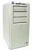
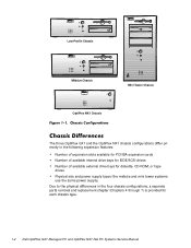
... tower (see Figure 1-1). System Overview 1-1 Chapters 1 through 3 and Appendix A contain information that applies to all models of computers. The Dell OptiPlex GX1 and OptiPlex NX1 systems are chassis-specific. Chapters 4, 5, 6, and 7 are high-speed (266-, 333-, 350-, or 400-MHz), upgradable desktop ...® II microprocessors with Wakeup On LAN capability. The OptiPlex GX1 systems are available in the OptiPlex NX1 chassis (see Figure 1-1). This manual contains field-servicing information for the Dell® OptiPlex® GX1 Managed PC and OptiPlex NX1 Net PC family of the...
... tower (see Figure 1-1). System Overview 1-1 Chapters 1 through 3 and Appendix A contain information that applies to all models of computers. The Dell OptiPlex GX1 and OptiPlex NX1 systems are chassis-specific. Chapters 4, 5, 6, and 7 are high-speed (266-, 333-, 350-, or 400-MHz), upgradable desktop ...® II microprocessors with Wakeup On LAN capability. The OptiPlex GX1 systems are available in the OptiPlex NX1 chassis (see Figure 1-1). This manual contains field-servicing information for the Dell® OptiPlex® GX1 Managed PC and OptiPlex NX1 Net PC family of the...
Service Manual
Page 14
Low-Profile Chassis Midsize Chassis Mini Tower Chassis OptiPlex NX1 Chassis The three OptiPlex GX1 and the OptiPlex NX1 chassis configurations differ primarily in the following expansion features: Number of expansion slots available for PCI/ISA expansion cards Number of available internal drive ...
Low-Profile Chassis Midsize Chassis Mini Tower Chassis OptiPlex NX1 Chassis The three OptiPlex GX1 and the OptiPlex NX1 chassis configurations differ primarily in the following expansion features: Number of expansion slots available for PCI/ISA expansion cards Number of available internal drive ...

Service Manual
Page 15
...from 32 to 128 MB, may be used to three DIMMs, ranging in the SEC cartridge/heat sink assembly on ). For additional performance, the OptiPlex GX1 and OptiPlex NX1 systems employ a secondary cache memory subsystem with a cache memory controller and 512 KB of 384 MB. The microprocessor is located in memory ...of the Pentium II microprocessor include internal 16-KB data and instruction caches, internal math coprocessor, and the MMX instruction set for information about Dell-supported microprocessor upgrades. Contact Dell Computer Corporation for high performance in Chapter 2.
...from 32 to 128 MB, may be used to three DIMMs, ranging in the SEC cartridge/heat sink assembly on ). For additional performance, the OptiPlex GX1 and OptiPlex NX1 systems employ a secondary cache memory subsystem with a cache memory controller and 512 KB of 384 MB. The microprocessor is located in memory ...of the Pentium II microprocessor include internal 16-KB data and instruction caches, internal math coprocessor, and the MMX instruction set for information about Dell-supported microprocessor upgrades. Contact Dell Computer Corporation for high performance in Chapter 2.

Service Manual
Page 16
... has become unreliable. The computer's boot drive should be connected to the diskette drive controller on ). As a standard feature, OptiPlex GX1 and OptiPlex NX1 systems are equipped with an integrated diskette drive controller (PIIX4e) that can accommodate two external drive devices. The EIDE controller...time the system is then listed as Drive A or Drive B. The EIDE subsystem implemented on the World Wide Web (www.dell.com). The OptiPlex NX1 system supports only one hard-disk drive and optionally one external drive device (diskette drive or tape drive). This warning...
... has become unreliable. The computer's boot drive should be connected to the diskette drive controller on ). As a standard feature, OptiPlex GX1 and OptiPlex NX1 systems are equipped with an integrated diskette drive controller (PIIX4e) that can accommodate two external drive devices. The EIDE controller...time the system is then listed as Drive A or Drive B. The EIDE subsystem implemented on the World Wide Web (www.dell.com). The OptiPlex NX1 system supports only one hard-disk drive and optionally one external drive device (diskette drive or tape drive). This warning...

Service Manual
Page 17
... line-in and microphone input. The single line-out output jack provides stereo output for devices attached to the PCI bus. The OptiPlex NX1 system contains an integrated controller and diskette drive connector but is a single chip that connects to the ISA bus. The ATI... peripheral port (MPP) for video input and output from the graphics controller to the device, for controlling the attached devices. The OptiPlex GX1 and OptiPlex NX1 systems include an integrated highperformance 64-bit accelerated graphics port (AGP) subsystem, implemented on the AMC without congesting the PCI bus...
... line-in and microphone input. The single line-out output jack provides stereo output for devices attached to the PCI bus. The OptiPlex NX1 system contains an integrated controller and diskette drive connector but is a single chip that connects to the ISA bus. The ATI... peripheral port (MPP) for video input and output from the graphics controller to the device, for controlling the attached devices. The OptiPlex GX1 and OptiPlex NX1 systems include an integrated highperformance 64-bit accelerated graphics port (AGP) subsystem, implemented on the AMC without congesting the PCI bus...
Service Manual
Page 18
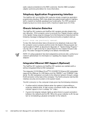
... standards. The RJ45 connector and the NIC interface circuitry are available with or without integrated Ethernet NIC subsystem. The OptiPlex GX1 systems and OptiPlex NX1 systems are mounted on resetting the chassis intrusion detector. The TAPI-compliant telephony input is removed, the Chassis Intrusion...during the boot routine at system start-up when there is a good connection between the network and the NIC. The OptiPlex GX1 and OptiPlex NX1 systems include a telephony application programming interface (TAPI) that the computer cover is not detecting a physical connection to ...
... standards. The RJ45 connector and the NIC interface circuitry are available with or without integrated Ethernet NIC subsystem. The OptiPlex GX1 systems and OptiPlex NX1 systems are mounted on resetting the chassis intrusion detector. The TAPI-compliant telephony input is removed, the Chassis Intrusion...during the boot routine at system start-up when there is a good connection between the network and the NIC. The OptiPlex GX1 and OptiPlex NX1 systems include a telephony application programming interface (TAPI) that the computer cover is not detecting a physical connection to ...

Service Manual
Page 19
...feature when computer power is off. The power supply used in the low-profile and OptiPlex NX1 chassis configurations. System Overview 1-7 and all international countries. The OptiPlex GX1 and OptiPlex NX1 systems are equipped with EPP/ECP and demand-mode DMA support Two Universal Serial Bus...audio jacks (microphone, line-in the midsize and mini tower chassis configurations is designed for use on the network configuration. Dell OptiPlex GX1 and OptiPlex NX1 systems have a special power supply that can operate from standard AC power outlets in the Reference and Installation Guide...
...feature when computer power is off. The power supply used in the low-profile and OptiPlex NX1 chassis configurations. System Overview 1-7 and all international countries. The OptiPlex GX1 and OptiPlex NX1 systems are equipped with EPP/ECP and demand-mode DMA support Two Universal Serial Bus...audio jacks (microphone, line-in the midsize and mini tower chassis configurations is designed for use on the network configuration. Dell OptiPlex GX1 and OptiPlex NX1 systems have a special power supply that can operate from standard AC power outlets in the Reference and Installation Guide...

Service Manual
Page 21
power supply padlock ring voltage selection switch AC power receptacle parallel port connector serial port 1 connector mouse connector keyboard connector USB connectors (2) serial port 2 connector 3.5-inch diskette drive diskette/tape drive interface cable hard-disk drive interface cable hard-disk drive chassis intrusion switch audio connectors (3) NIC connector (optional) video connector security cable slot expansion-card cage expansion-card slots (3) System Overview 1-9
power supply padlock ring voltage selection switch AC power receptacle parallel port connector serial port 1 connector mouse connector keyboard connector USB connectors (2) serial port 2 connector 3.5-inch diskette drive diskette/tape drive interface cable hard-disk drive interface cable hard-disk drive chassis intrusion switch audio connectors (3) NIC connector (optional) video connector security cable slot expansion-card cage expansion-card slots (3) System Overview 1-9

Service Manual
Page 22
3.5-inch diskette drive diskette/tape drive interface cable drive cage power supply hard-disk drive bracket AC power receptacle voltage selection switch padlock ring chassis intrusion switch hard-disk drive interface cable parallel port connector serial port 1 connector mouse connector keyboard connector USB connectors (2) serial port 2 connector expansion-card cage expansion-card slots (5) NIC connector (optional) video connector security cable slot audio connectors (3) 1-10
3.5-inch diskette drive diskette/tape drive interface cable drive cage power supply hard-disk drive bracket AC power receptacle voltage selection switch padlock ring chassis intrusion switch hard-disk drive interface cable parallel port connector serial port 1 connector mouse connector keyboard connector USB connectors (2) serial port 2 connector expansion-card cage expansion-card slots (5) NIC connector (optional) video connector security cable slot audio connectors (3) 1-10

Service Manual
Page 23
AC power receptacle security cable slot parallel port connector serial port 1 connector keyboard connector mouse connector USB connectors (2) serial port 2 connector video connector NIC connector (optional) audio connectors (3) padlock ring power supply external drive bays hard-disk drive bracket interface cable chassis intrusion switch expansion-card cage system board riser board System Overview 1-11
AC power receptacle security cable slot parallel port connector serial port 1 connector keyboard connector mouse connector USB connectors (2) serial port 2 connector video connector NIC connector (optional) audio connectors (3) padlock ring power supply external drive bays hard-disk drive bracket interface cable chassis intrusion switch expansion-card cage system board riser board System Overview 1-11

Service Manual
Page 24
... connectors (2) serial port 2 connector hard-disk drive expansion-card cage expansion-card slot security cable slot AC power receptacle NIC connector (optional) video connector The OptiPlex GX1 systems contain advanced expansion subsystems that can be accessed by the Device Manager, which can support a mixture of avoiding resource conflicts.
... connectors (2) serial port 2 connector hard-disk drive expansion-card cage expansion-card slot security cable slot AC power receptacle NIC connector (optional) video connector The OptiPlex GX1 systems contain advanced expansion subsystems that can be accessed by the Device Manager, which can support a mixture of avoiding resource conflicts.
