
Service Manual
Page 5
... Supply 4-11 Expansion Cards 4-12 Expansion-Card Cage 4-12 Expansion Card 4-13 Riser Board 4-14 System Board 4-15 System Board Components 4-16 DIMMs 4-17 Video Memory 4-18 Microprocessor 4-19 SEC Cartridge/Heat Sink Assembly 4-19 System Battery 4-20 Recommended Tools 5-1 Precautionary Measures 5-1 Inside the Computer 5-2 Optional Stand 5-4 Computer Cover 5-5 Eject, Power...
... Supply 4-11 Expansion Cards 4-12 Expansion-Card Cage 4-12 Expansion Card 4-13 Riser Board 4-14 System Board 4-15 System Board Components 4-16 DIMMs 4-17 Video Memory 4-18 Microprocessor 4-19 SEC Cartridge/Heat Sink Assembly 4-19 System Battery 4-20 Recommended Tools 5-1 Precautionary Measures 5-1 Inside the Computer 5-2 Optional Stand 5-4 Computer Cover 5-5 Eject, Power...

Service Manual
Page 6
... Supply 5-14 Expansion Cards 5-15 Expansion-Card Cage 5-15 Expansion Card 5-16 Riser Board 5-17 System Board 5-18 System Board Components 5-19 DIMMs 5-20 Video Memory 5-21 Microprocessor 5-22 SEC Cartridge/Heat Sink Assembly 5-22 System Battery 5-23 Recommended Tools 6-1 Precautionary Measures 6-1 Inside the Computer 6-2 Computer Cover 6-4 Front Bezel 6-5 Eject, Power...
... Supply 5-14 Expansion Cards 5-15 Expansion-Card Cage 5-15 Expansion Card 5-16 Riser Board 5-17 System Board 5-18 System Board Components 5-19 DIMMs 5-20 Video Memory 5-21 Microprocessor 5-22 SEC Cartridge/Heat Sink Assembly 5-22 System Battery 5-23 Recommended Tools 6-1 Precautionary Measures 6-1 Inside the Computer 6-2 Computer Cover 6-4 Front Bezel 6-5 Eject, Power...

Service Manual
Page 7
...Disk Drive 7-7 System Power Supply 7-8 Expansion-Card Cage 7-9 Expansion Card 7-10 Riser Board 7-11 System Board 7-12 System Board Components 7-13 DIMMs 7-14 Video Memory 7-15 Microprocessor 7-16 SEC Cartridge/Heat Sink Assembly 7-16 System Battery 7-17 System Setup Screens A-2 Device List A-7 Figure 1-1. Figure 1-3. Figure 1-6. Chassis Configurations...1-9 Internal View of the Midsize Chassis 1-10 Internal View of the Mini Tower Chassis 1-11 Internal View of the OptiPlex NX1 Chassis 1-12 Riser Board for the OptiPlex NX1 Computer 1-13 ix Figure 1-4. Figure 1-7.
...Disk Drive 7-7 System Power Supply 7-8 Expansion-Card Cage 7-9 Expansion Card 7-10 Riser Board 7-11 System Board 7-12 System Board Components 7-13 DIMMs 7-14 Video Memory 7-15 Microprocessor 7-16 SEC Cartridge/Heat Sink Assembly 7-16 System Battery 7-17 System Setup Screens A-2 Device List A-7 Figure 1-1. Figure 1-3. Figure 1-6. Chassis Configurations...1-9 Internal View of the Midsize Chassis 1-10 Internal View of the Mini Tower Chassis 1-11 Internal View of the OptiPlex NX1 Chassis 1-12 Riser Board for the OptiPlex NX1 Computer 1-13 ix Figure 1-4. Figure 1-7.
Service Manual
Page 9
... 5-21. Figure 6-1. Figure 6-3. Figure 4-17. Figure 5-11. Figure 6-12. DIMM Removal 4-17 DIMM Installation 4-17 Installing a Video-Memory Upgrade Module 4-18 SEC Cartridge/Heat Sink Removal 4-19 System Battery Installation 4-20 Internal View of the Midsize Computer 5-3 Optional-Stand Removal 5-4...Removal 5-17 System Board Removal 5-18 System Board Components 5-19 DIMM Removal 5-20 DIMM Installation 5-20 Installing a Video-Memory Upgrade Module 5-21 SEC Cartridge/Heat Sink Removal 5-22 System Battery Installation 5-23 Internal View of the Mini Tower ...
... 5-21. Figure 6-1. Figure 6-3. Figure 4-17. Figure 5-11. Figure 6-12. DIMM Removal 4-17 DIMM Installation 4-17 Installing a Video-Memory Upgrade Module 4-18 SEC Cartridge/Heat Sink Removal 4-19 System Battery Installation 4-20 Internal View of the Midsize Computer 5-3 Optional-Stand Removal 5-4...Removal 5-17 System Board Removal 5-18 System Board Components 5-19 DIMM Removal 5-20 DIMM Installation 5-20 Installing a Video-Memory Upgrade Module 5-21 SEC Cartridge/Heat Sink Removal 5-22 System Battery Installation 5-23 Internal View of the Mini Tower ...
Service Manual
Page 10
... 6-19 System Board Removal 6-20 System Board Components 6-21 DIMM Removal 6-22 DIMM Installation 6-22 Installing a Video-Memory Upgrade Module 6-23 SEC Cartridge/Heat Sink Removal 6-24 System Battery Installation 6-25 Internal View of the OptiPlex NX1 Computer 7-3 Optional-Stand Removal 7-3 Computer Cover Removal 7-4 Service Access Lock 7-5 Control Panel Removal 7-6 Hard-Disk...
... 6-19 System Board Removal 6-20 System Board Components 6-21 DIMM Removal 6-22 DIMM Installation 6-22 Installing a Video-Memory Upgrade Module 6-23 SEC Cartridge/Heat Sink Removal 6-24 System Battery Installation 6-25 Internal View of the OptiPlex NX1 Computer 7-3 Optional-Stand Removal 7-3 Computer Cover Removal 7-4 Service Access Lock 7-5 Control Panel Removal 7-6 Hard-Disk...

Service Manual
Page 15
...located in a single-edge contact (SEC) cartridge/heat sink assembly on ). Main memory for the OptiPlex GX1 and OptiPlex NX1 systems ranges from 32 to 128 MB, may be used to provide a maximum memory capacity of the Pentium II microprocessor include internal 16-KB data and instruction caches, ...32 MB to a maximum of pipeline-burst SRAM cache memory. All main memory is implemented using high-speed ECC and non-ECC DIMMs. One to three DIMMs, ranging in parallel for information about Dell-supported microprocessor upgrades. However, the OptiPlex NX1 computer has no built-in diskette drive and ...
...located in a single-edge contact (SEC) cartridge/heat sink assembly on ). Main memory for the OptiPlex GX1 and OptiPlex NX1 systems ranges from 32 to 128 MB, may be used to provide a maximum memory capacity of the Pentium II microprocessor include internal 16-KB data and instruction caches, ...32 MB to a maximum of pipeline-burst SRAM cache memory. All main memory is implemented using high-speed ECC and non-ECC DIMMs. One to three DIMMs, ranging in parallel for information about Dell-supported microprocessor upgrades. However, the OptiPlex NX1 computer has no built-in diskette drive and ...

Service Manual
Page 17
... controller 4-MB synchronous graphics random-access memory (SGRAM) video memory (expandable to 8 MB via a video-memory upgrade kit) 15-hole monitor port The integrated audio controller is a single chip that connects to the PCI bus. The OptiPlex GX1 and OptiPlex NX1 systems include an integrated highperformance 64...without congesting the PCI bus bandwidth. A fourth port, audio mixing bus (AMB), is 1600 x 1200 with a diskette drive. The OptiPlex NX1 system contains an integrated controller and diskette drive connector but is not equipped with 65,535 colors at 75 Hz. The maximum supported...
... controller 4-MB synchronous graphics random-access memory (SGRAM) video memory (expandable to 8 MB via a video-memory upgrade kit) 15-hole monitor port The integrated audio controller is a single chip that connects to the PCI bus. The OptiPlex GX1 and OptiPlex NX1 systems include an integrated highperformance 64...without congesting the PCI bus bandwidth. A fourth port, audio mixing bus (AMB), is 1600 x 1200 with a diskette drive. The OptiPlex NX1 system contains an integrated controller and diskette drive connector but is not equipped with 65,535 colors at 75 Hz. The maximum supported...

Service Manual
Page 25
The computer automatically assigns any required memory space, IRQ lines, and DMA channels to the riser board cable...is not receiving power. LED ISA2 connector HDLED connector P1 connector ISA1 connector PCI2 connector PCI1 connector The OptiPlex GX1 midsize computers have three expansion-card slots. Option 1 has three ISA expansion-card connectors and three ...PCI expansion-card connectors. power LED Wakeup On LAN power connector PCI1 connector The OptiPlex GX1 low-profile computers have five expansion-card slots. if off, the riser board is receiving power;...
The computer automatically assigns any required memory space, IRQ lines, and DMA channels to the riser board cable...is not receiving power. LED ISA2 connector HDLED connector P1 connector ISA1 connector PCI2 connector PCI1 connector The OptiPlex GX1 midsize computers have three expansion-card slots. Option 1 has three ISA expansion-card connectors and three ...PCI expansion-card connectors. power LED Wakeup On LAN power connector PCI1 connector The OptiPlex GX1 low-profile computers have five expansion-card slots. if off, the riser board is receiving power;...

Service Manual
Page 27
... ISA4 ISA3 ISA2 ISA1 P1 connector HDLED connector The system board has various accommodations for system upgrades including: Microprocessor upgrade Main memory expansion Video memory expansion These upgrades are implemented in a total of seven expansion-card slots (see Figure 1-11). The riser board is ... in an SEC cartridge/heat sink assembly. if off, the riser board is receiving power; On the OptiPlex GX1 and OptiPlex NX1 systems, the microprocessor and secondary L2 cache memory are summarized in Chapters 4, 5, 6, and 7. System Overview 1-15 The riser board has four ISA ...
... ISA4 ISA3 ISA2 ISA1 P1 connector HDLED connector The system board has various accommodations for system upgrades including: Microprocessor upgrade Main memory expansion Video memory expansion These upgrades are implemented in a total of seven expansion-card slots (see Figure 1-11). The riser board is ... in an SEC cartridge/heat sink assembly. if off, the riser board is receiving power; On the OptiPlex GX1 and OptiPlex NX1 systems, the microprocessor and secondary L2 cache memory are summarized in Chapters 4, 5, 6, and 7. System Overview 1-15 The riser board has four ISA ...

Service Manual
Page 28
... memory increases the system's video performance and provides additional modes for additional upgrade information. Unless otherwise specified, the information applies to 8 MB by a system administrator at a remote location: Perform computer setup processes Download and install software Perform file updates Perform asset-tracking functions Download and run the diagnostics over the network Dell OptiPlex...
... memory increases the system's video performance and provides additional modes for additional upgrade information. Unless otherwise specified, the information applies to 8 MB by a system administrator at a remote location: Perform computer setup processes Download and install software Perform file updates Perform asset-tracking functions Download and run the diagnostics over the network Dell OptiPlex...
Service Manual
Page 29
... are available to the system board. The OptiPlex NX1 systems use server-based diagnostics, hard-disk-based diagnostics, or the diskette-based diagnostics using an external diskette-drive kit connected directly to aid in jack (LINE-IN) CD-ROM audio interface connector (CD_IN) video-memory upgrade socket (VIDEO_UPGRADE) ATI multimedia connector (AMC... input connector (POWER_1) 3.3-V power input connector (POWER_2) system board jumpers primary EIDE diskette/tape drive interface connector interface connector (IDE1) (DSKT) front of the three Dell OptiPlex GX1 chassis.
... are available to the system board. The OptiPlex NX1 systems use server-based diagnostics, hard-disk-based diagnostics, or the diskette-based diagnostics using an external diskette-drive kit connected directly to aid in jack (LINE-IN) CD-ROM audio interface connector (CD_IN) video-memory upgrade socket (VIDEO_UPGRADE) ATI multimedia connector (AMC... input connector (POWER_1) 3.3-V power input connector (POWER_2) system board jumpers primary EIDE diskette/tape drive interface connector interface connector (IDE1) (DSKT) front of the three Dell OptiPlex GX1 chassis.

Service Manual
Page 40
... ISA3 +12 VDC FAN internal P2 hard-disk drive internal P3 hard-disk drive P4 3.5-inch diskette drive P5* optional drive P6* optional drive main memory DIMM_A DIMM_B DIMM_C +5 VFP +5 VDC +5 VDC +5 VDC +5 VDC MICROPROCESSOR processor core regulator +3.3 VDC core VCC +2.1 to +3.5 VDC PANEL USB KYBD fuses (2) MOUSE NOTE: +5 VFP is...
... ISA3 +12 VDC FAN internal P2 hard-disk drive internal P3 hard-disk drive P4 3.5-inch diskette drive P5* optional drive P6* optional drive main memory DIMM_A DIMM_B DIMM_C +5 VFP +5 VDC +5 VDC +5 VDC +5 VDC MICROPROCESSOR processor core regulator +3.3 VDC core VCC +2.1 to +3.5 VDC PANEL USB KYBD fuses (2) MOUSE NOTE: +5 VFP is...
Service Manual
Page 41
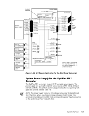
... hard-disk drive internal P3 hard-disk drive P4 3.5-inch diskette drive P5 optional drive P6 optional drive P9 optional drive +12 VDC FAN main memory DIMM_A DIMM_B DIMM_C +5 VFP +5 VDC +5 VDC +5 VDC PANEL USB KYBD +5 VDC processor MICROPROCESSOR core regulator +3.3 VDC core VCC +2.1 to +3.5 VDC MOUSE NOTE: +5... VFP is routed to the integrated NIC logic on the system board and to their corresponding power input connectors on the riser board. The OptiPlex NX1 computers have an 80-W computer power supply. The power supply can operate from an AC power source of 115 VAC at 60 Hz ...
... hard-disk drive internal P3 hard-disk drive P4 3.5-inch diskette drive P5 optional drive P6 optional drive P9 optional drive +12 VDC FAN main memory DIMM_A DIMM_B DIMM_C +5 VFP +5 VDC +5 VDC +5 VDC PANEL USB KYBD +5 VDC processor MICROPROCESSOR core regulator +3.3 VDC core VCC +2.1 to +3.5 VDC MOUSE NOTE: +5... VFP is routed to the integrated NIC logic on the system board and to their corresponding power input connectors on the riser board. The OptiPlex NX1 computers have an 80-W computer power supply. The power supply can operate from an AC power source of 115 VAC at 60 Hz ...

Service Manual
Page 44
... +3.3 VDC +5 VDC +12 VDC -12 VDC RISER +3.3 VDC +5 VDC +12 VDC -12 VDC riser board P1 PCI1 internal P3 hard-disk drive +12 VDC main memory sockets DIMM_A DIMM_B DIMM_C +5 VFP +5 VDC +5 VDC +5 VDC +5 VDC MICROPROCESSOR processor core regulator +3.3 VDC core VCC +2.1 to +3.5 VDC FAN PANEL USB KYBD fuses (2) MOUSE NOTE...
... +3.3 VDC +5 VDC +12 VDC -12 VDC RISER +3.3 VDC +5 VDC +12 VDC -12 VDC riser board P1 PCI1 internal P3 hard-disk drive +12 VDC main memory sockets DIMM_A DIMM_B DIMM_C +5 VFP +5 VDC +5 VDC +5 VDC +5 VDC MICROPROCESSOR processor core regulator +3.3 VDC core VCC +2.1 to +3.5 VDC FAN PANEL USB KYBD fuses (2) MOUSE NOTE...

Service Manual
Page 46
one 5.25-inch bay for a 3.5-inch diskette drive; Mini tower computers OptiPlex NX1 computers two (one ISA connector and one PCI connector share an expansion-card slot) three (one ISA connector and one 3.5-inch bay for a diskette, ... 3Com PCI 3C905B-TX Wakeup On LAN NIC, operating at 10 or 100 Mbps Architecture DIMM sockets DIMM capacities Standard RAM Maximum RAM L2 cache memory BIOS address ROM address 64-bit (nonparity) or 72-bit (parity), noninterleaved three (gold contacts) 32-MB nonparity SDRAM; 32-, 64-, and 128-MB parity...
one 5.25-inch bay for a 3.5-inch diskette drive; Mini tower computers OptiPlex NX1 computers two (one ISA connector and one PCI connector share an expansion-card slot) three (one ISA connector and one 3.5-inch bay for a diskette, ... 3Com PCI 3C905B-TX Wakeup On LAN NIC, operating at 10 or 100 Mbps Architecture DIMM sockets DIMM capacities Standard RAM Maximum RAM L2 cache memory BIOS address ROM address 64-bit (nonparity) or 72-bit (parity), noninterleaved three (gold contacts) 32-MB nonparity SDRAM; 32-, 64-, and 128-MB parity...

Service Manual
Page 47
... computers one bay for a 3.5-inch diskette drive; Mini tower computers OptiPlex NX1 computers Internal hard-disk drive bays: Low-profile computers Midsize computers . . . . three 5.25-inch bays for diskette, tape, or CD-ROM drives none one ...-disk drive and one 1.6-inch-high EIDE or SCSI hard-disk drive one 3.5-inch bay for a 1-inch-high EIDE hard-disk drive Video type Video memory Video resolutions integrated ATI Rage Pro (AGP 2X) graphics 4-MB SGRAM, upgradable to 8 MB 640 x 480 (32 bpp), True-color, 85 Hz, minimum 4 MB video...
... computers one bay for a 3.5-inch diskette drive; Mini tower computers OptiPlex NX1 computers Internal hard-disk drive bays: Low-profile computers Midsize computers . . . . three 5.25-inch bays for diskette, tape, or CD-ROM drives none one ...-disk drive and one 1.6-inch-high EIDE or SCSI hard-disk drive one 3.5-inch bay for a 1-inch-high EIDE hard-disk drive Video type Video memory Video resolutions integrated ATI Rage Pro (AGP 2X) graphics 4-MB SGRAM, upgradable to 8 MB 640 x 480 (32 bpp), True-color, 85 Hz, minimum 4 MB video...
Service Manual
Page 57
..., check the system and reassign the resources as necessary. Proceed to two or more devices. No further steps are necessary. Because a device may require dedicated memory spaces, interrupt levels, or DMA channels, all . Basic Troubleshooting 2-5 The microprocessor is assigned to the next sections, "Eliminating Resource Conflicts," "Running the System Diagnostics," and...
..., check the system and reassign the resources as necessary. Proceed to two or more devices. No further steps are necessary. Because a device may require dedicated memory spaces, interrupt levels, or DMA channels, all . Basic Troubleshooting 2-5 The microprocessor is assigned to the next sections, "Eliminating Resource Conflicts," "Running the System Diagnostics," and...

Service Manual
Page 60
... functionality of the mouse controller and the operation of the keyboard and the keyboard controller chip Mouse Test - Starting the diagnostics causes the Dell logo to isolate a failure Run All Tests - Runs selected tests from the hard-disk drive. Otherwise, see "Internal Visual Inspection" ...a thorough test of the video controller and the video control circuitry Keyboard Tests - If a main memory error is loading. This menu lets you are found earlier in main memory, the diagnostics loads and the Diagnostics Menu appears. Check the computer's system board components and verify...
... functionality of the mouse controller and the operation of the keyboard and the keyboard controller chip Mouse Test - Starting the diagnostics causes the Dell logo to isolate a failure Run All Tests - Runs selected tests from the hard-disk drive. Otherwise, see "Internal Visual Inspection" ...a thorough test of the video controller and the video control circuitry Keyboard Tests - If a main memory error is loading. This menu lets you are found earlier in main memory, the diagnostics loads and the Diagnostics Menu appears. Check the computer's system board components and verify...

Service Manual
Page 62
...Runs all test groups to quickly locate a failure or to the MS-DOS prompt: Run Quick Tests - If no errors are found in main memory, the diagnostics loads and the Diagnostics Menu appears. To install the external diskette drive, follow these steps: To run the diskette-based diagnostics, ...follow these steps: Starting the diagnostics causes the Dell logo to appear on the monitor screen, followed by a message indicating that the diagnostics is needed to isolate a failure Run All Tests - ...
...Runs all test groups to quickly locate a failure or to the MS-DOS prompt: Run Quick Tests - If no errors are found in main memory, the diagnostics loads and the Diagnostics Menu appears. To install the external diskette drive, follow these steps: To run the diskette-based diagnostics, ...follow these steps: Starting the diagnostics causes the Dell logo to appear on the monitor screen, followed by a message indicating that the diagnostics is needed to isolate a failure Run All Tests - ...

Service Manual
Page 66
... Odd/even logic failure in the first 64 KB of main memory Address line failure in the first 64 KB of main memory Parity failure in the first 64 KB of main memory Bit failure in the first 64 KB of main memory Slave DMA-register failure Defective system board Master DMA-register failure... subsystem (defective system board) Search for video ROM failure No timer tick Defective system board Shutdown failure Gate A20 failure Unexpected interrupt in protected mode Memory failure above address 0FFFFh Timer-chip counter 2 failure Faulty or improperly seated DIMM Defective system board 3-2
... Odd/even logic failure in the first 64 KB of main memory Address line failure in the first 64 KB of main memory Parity failure in the first 64 KB of main memory Bit failure in the first 64 KB of main memory Slave DMA-register failure Defective system board Master DMA-register failure... subsystem (defective system board) Search for video ROM failure No timer tick Defective system board Shutdown failure Gate A20 failure Unexpected interrupt in protected mode Memory failure above address 0FFFFh Timer-chip counter 2 failure Faulty or improperly seated DIMM Defective system board 3-2


