Service Manual
Page 4
... 1-22 Hard-Disk Drive for the OptiPlex NX1 Computer 1-22 Power-Supply Service Data 1-22 Pin Assignments for the DC Power Connectors 1-23 DC Power Distribution 1-24 System Power Supply for the OptiPlex NX1 Computer 1-29 OptiPlex NX1 Pin Assignments for the DC Power Connectors .... . 1-30 DC Power Distribution for the OptiPlex NX1 Computer 1-31 Technical Specifications 1-33 Initial User Contact 2-1 External Visual Inspection...
... 1-22 Hard-Disk Drive for the OptiPlex NX1 Computer 1-22 Power-Supply Service Data 1-22 Pin Assignments for the DC Power Connectors 1-23 DC Power Distribution 1-24 System Power Supply for the OptiPlex NX1 Computer 1-29 OptiPlex NX1 Pin Assignments for the DC Power Connectors .... . 1-30 DC Power Distribution for the OptiPlex NX1 Computer 1-31 Technical Specifications 1-33 Initial User Contact 2-1 External Visual Inspection...

Service Manual
Page 16
...is implemented in flash ROM, which allows for easy BIOS upgrades using diskette files or files downloaded from Dell's home page on ). NOTES: If the diskette drive and tape drive are both attached to two ...) provides support for diskette, CD-ROM, and/or tape drives. As a standard feature, OptiPlex GX1 and OptiPlex NX1 systems are equipped with Self-Monitoring and Analysis Reporting Technology (SMART), which tests the system...if you at the front of two non-EIDE diskette and tape drives via a 34-pin DSKT connector located on the system board, only the diskette drive is then listed as...
...is implemented in flash ROM, which allows for easy BIOS upgrades using diskette files or files downloaded from Dell's home page on ). NOTES: If the diskette drive and tape drive are both attached to two ...) provides support for diskette, CD-ROM, and/or tape drives. As a standard feature, OptiPlex GX1 and OptiPlex NX1 systems are equipped with Self-Monitoring and Analysis Reporting Technology (SMART), which tests the system...if you at the front of two non-EIDE diskette and tape drives via a 34-pin DSKT connector located on the system board, only the diskette drive is then listed as...

Service Manual
Page 17
.... This architecture also off-loads the PCI bus providing greater performance for a line-level input to do both simultaneously. The 40-pin AMC connector, shown in Figure 1-12, consists of the video stream data transfers occur on the system board, which drives an external...Troubleshooting." See "Technical Specifications" found later in this computer requires an external diskette-drive kit as described in and microphone input. The OptiPlex NX1 system contains an integrated controller and diskette drive connector but is a single chip that connects to the ISA bus. The audio controller...
.... This architecture also off-loads the PCI bus providing greater performance for a line-level input to do both simultaneously. The 40-pin AMC connector, shown in Figure 1-12, consists of the video stream data transfers occur on the system board, which drives an external...Troubleshooting." See "Technical Specifications" found later in this computer requires an external diskette-drive kit as described in and microphone input. The OptiPlex NX1 system contains an integrated controller and diskette drive connector but is a single chip that connects to the ISA bus. The audio controller...

Service Manual
Page 19
.... Figures 1-3 through 1-6 for I/O port identifiers for the four chassis types; Dell OptiPlex GX1 and OptiPlex NX1 systems have a special power supply that used in the U.S. For desktop connectivity, the OptiPlex GX1 and OptiPlex NX1 systems include the following ports: 25-hole, bidirectional parallel port with a ... chassis configurations. System Overview 1-7 The OptiPlex GX1 and OptiPlex NX1 systems are equipped with EPP/ECP and demand-mode DMA support Two Universal Serial Bus (USB) ports Two 9-pin serial ports Two PS/2 ports (mouse and keyboard) One 15-hole video connector ...
.... Figures 1-3 through 1-6 for I/O port identifiers for the four chassis types; Dell OptiPlex GX1 and OptiPlex NX1 systems have a special power supply that used in the U.S. For desktop connectivity, the OptiPlex GX1 and OptiPlex NX1 systems include the following ports: 25-hole, bidirectional parallel port with a ... chassis configurations. System Overview 1-7 The OptiPlex GX1 and OptiPlex NX1 systems are equipped with EPP/ECP and demand-mode DMA support Two Universal Serial Bus (USB) ports Two 9-pin serial ports Two PS/2 ports (mouse and keyboard) One 15-hole video connector ...

Service Manual
Page 35
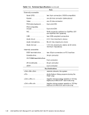
... 10 +5 VDC (red) common (black) common (black) +5 VDC (red) common (black) PWRGOOD 3 (orange) common (black) -12 VDC (blue) +12 VDC (yellow) +5 VFP (purple) 1 Pin 11 - PSON# should measure between +4 and +5 VDC except when the power button on and operating to control the power-supply fan speed...-5 VDC -4.50 to -5.50 VDC 0.3 A (low-profile computers); 0.3 A (midsize and mini tower computers) +5 VFP3 +4.75 to its active-low state. 2 Pin 19 - System Overview 1-23 Thermal fan-speed control (TFSC) is pressed, taking PSON# to +5.25 VDC 10 mA 3 VFP (volts flea power) - Figures ...
... 10 +5 VDC (red) common (black) common (black) +5 VDC (red) common (black) PWRGOOD 3 (orange) common (black) -12 VDC (blue) +12 VDC (yellow) +5 VFP (purple) 1 Pin 11 - PSON# should measure between +4 and +5 VDC except when the power button on and operating to control the power-supply fan speed...-5 VDC -4.50 to -5.50 VDC 0.3 A (low-profile computers); 0.3 A (midsize and mini tower computers) +5 VFP3 +4.75 to its active-low state. 2 Pin 19 - System Overview 1-23 Thermal fan-speed control (TFSC) is pressed, taking PSON# to +5.25 VDC 10 mA 3 VFP (volts flea power) - Figures ...

Service Manual
Page 42
... 9 10 +5 VDC (red) common (black) common (black) +5 VDC (red) common (black) PWRGOOD 3 (orange) common (black) -12 VDC (blue) +12 VDC (yellow) +5 VFP (purple) 1 Pin 11 - PSON# should not exceed 65 W. 2 Withstands surges of up to 3.0 A to support disk start-up operations. 3 VFP (volts flea power) - The power-supply output... +3.3-VDC outputs should measure between +4 and +5 VDC when the power supply is a power-supply input signal used to control the power-supply fan speed. 3 Pin 5 - 1-30 . 1 +3.3 VDC +3.14 to +3.47 VDC 6.0 A1 +5 VDC +4.75 to +5.25 VDC 12.0 A1 +12 VDC +11.40...
... 9 10 +5 VDC (red) common (black) common (black) +5 VDC (red) common (black) PWRGOOD 3 (orange) common (black) -12 VDC (blue) +12 VDC (yellow) +5 VFP (purple) 1 Pin 11 - PSON# should not exceed 65 W. 2 Withstands surges of up to 3.0 A to support disk start-up operations. 3 VFP (volts flea power) - The power-supply output... +3.3-VDC outputs should measure between +4 and +5 VDC when the power supply is a power-supply input signal used to control the power-supply fan speed. 3 Pin 5 - 1-30 . 1 +3.3 VDC +3.14 to +3.47 VDC 6.0 A1 +5 VDC +4.75 to +5.25 VDC 12.0 A1 +12 VDC +11.40...
Service Manual
Page 48
two 40-pin connectors on OptiPlex GX1 and OptiPlex NX1 systems) USB two USB-compliant connectors Audio line-in 2.0-V rms (maximum); Externally accessible: Serial (DTE two 9-pin connectors (16550-compatible) Parallel one 25-hole connector (bidirectional) Video one 15-hole connector PS/2-style keyboard . . . . 6-pin mini-DIN PS/2-compatible mouse 6-pin mini-DIN NIC RJ45 connector (optional...
two 40-pin connectors on OptiPlex GX1 and OptiPlex NX1 systems) USB two USB-compliant connectors Audio line-in 2.0-V rms (maximum); Externally accessible: Serial (DTE two 9-pin connectors (16550-compatible) Parallel one 25-hole connector (bidirectional) Video one 15-hole connector PS/2-style keyboard . . . . 6-pin mini-DIN PS/2-compatible mouse 6-pin mini-DIN NIC RJ45 connector (optional...
Service Manual
Page 134
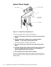
When you reinstall the system power supply, place the power-supply detent link over the pin on the power supply as you position the power supply in the chassis opening. 6-16 power supply DC power cables slot power-supply detent link securing tab To remove the system power supply, follow these steps: Press the securing tab to release the power supply.
When you reinstall the system power supply, place the power-supply detent link over the pin on the power supply as you position the power supply in the chassis opening. 6-16 power supply DC power cables slot power-supply detent link securing tab To remove the system power supply, follow these steps: Press the securing tab to release the power supply.
Service Manual
Page 147
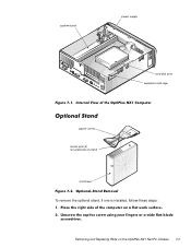
system board power supply hard-disk drive expansion-card cage captive screw locator pins (2) (on underside of stand) front bezel To remove the optional stand, if one is installed, follow these steps: Removing and Replacing Parts on the OptiPlex NX1 Net PC Chassis 7-3
system board power supply hard-disk drive expansion-card cage captive screw locator pins (2) (on underside of stand) front bezel To remove the optional stand, if one is installed, follow these steps: Removing and Replacing Parts on the OptiPlex NX1 Net PC Chassis 7-3
Service Manual
Page 148
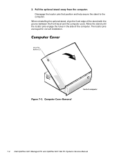
Move the stand until the locator pins engage the holes in the side of computer 7-4 securing buttons (2) front of the computer. When reinstalling the optional stand, align the front edge of the stand with the groove between the front bezel and the computer cover. The locator pins are keyed for correct installation. Disengage the locator pins that position and help secure the stand to the computer.
Move the stand until the locator pins engage the holes in the side of computer 7-4 securing buttons (2) front of the computer. When reinstalling the optional stand, align the front edge of the stand with the groove between the front bezel and the computer cover. The locator pins are keyed for correct installation. Disengage the locator pins that position and help secure the stand to the computer.
Service Manual
Page 172
... 1-7 cover removal, low-profile computer, 4-3 cover removal, midsize computer, 5-5 cover removal, mini tower computer, 6-4 cover removal, OptiPlex NX1 computer, 7-4 diagnostics. See diagnostics DMA channel assignments, 1-20 expansion features, 1-12 features, 1-1, 1-3 front-panel views, 1-8 ... and mini tower computers, 1-27 cables, OptiPlex NX1 computer, 1-32 connector pin assignments, low-profile computer, 1-23 connector pin assignments, midsize computer, 1-23 connector pin assignments, mini tower computer, 1-23 connector pin assignments, OptiPlex NX1 computer, 1-30, 1-31 distribution, low...
... 1-7 cover removal, low-profile computer, 4-3 cover removal, midsize computer, 5-5 cover removal, mini tower computer, 6-4 cover removal, OptiPlex NX1 computer, 7-4 diagnostics. See diagnostics DMA channel assignments, 1-20 expansion features, 1-12 features, 1-1, 1-3 front-panel views, 1-8 ... and mini tower computers, 1-27 cables, OptiPlex NX1 computer, 1-32 connector pin assignments, low-profile computer, 1-23 connector pin assignments, midsize computer, 1-23 connector pin assignments, mini tower computer, 1-23 connector pin assignments, OptiPlex NX1 computer, 1-30, 1-31 distribution, low...


