User Manual
Page 1
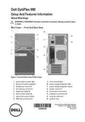
Dell OptiPlex 990 Setup And Features Information About Warnings WARNING: A WARNING indicates a potential for property damage, personal injury, or death. Front And Back View Of Mini Tower 1. microphone connector 5. power supply diagnostic light 11. expansion-card slots (4) 15. USB 2.0 connectors (4) 9. power connector 13. power button, power light 2. drive activity light... slot 16. optical-drive eject button 8. power supply diagnostic button 12. diagnostic lights (4) 6. back panel connectors 14. headphone connector 4. Front And Back View Figure 1. Mini Tower -
Dell OptiPlex 990 Setup And Features Information About Warnings WARNING: A WARNING indicates a potential for property damage, personal injury, or death. Front And Back View Of Mini Tower 1. microphone connector 5. power supply diagnostic light 11. expansion-card slots (4) 15. USB 2.0 connectors (4) 9. power connector 13. power button, power light 2. drive activity light... slot 16. optical-drive eject button 8. power supply diagnostic button 12. diagnostic lights (4) 6. back panel connectors 14. headphone connector 4. Front And Back View Figure 1. Mini Tower -
User Manual
Page 2
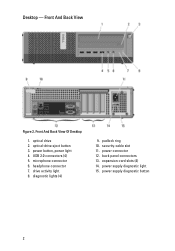
drive activity light 8. padlock ring 10. security-cable slot 11. Desktop - power connector 12. power button, power light 4. diagnostic lights (4) 9. back panel connectors 13. power supply diagnostic button 2 optical-drive eject button 3. expansion-card slots (4) 14. power supply diagnostic light 15. optical drive 2. microphone connector 6. Front And Back View Figure 2. Front And Back View Of Desktop 1. headphone connector 7. USB 2.0 connectors (4) 5.
drive activity light 8. padlock ring 10. security-cable slot 11. Desktop - power connector 12. power button, power light 4. diagnostic lights (4) 9. back panel connectors 13. power supply diagnostic button 2 optical-drive eject button 3. expansion-card slots (4) 14. power supply diagnostic light 15. optical drive 2. microphone connector 6. Front And Back View Figure 2. Front And Back View Of Desktop 1. headphone connector 7. USB 2.0 connectors (4) 5.
User Manual
Page 3
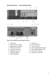
Small Form Factor - optical drive 2. microphone connector 6. padlock ring 10. optical-drive eject button 3. Front And Back View Figure 3. power supply diagnostic light 14. back panel connectors 15. power button, power light 4. headphone connector 7. diagnostic lights (4) 8. security-cable slot 11. drive activity light 9. power supply diagnostic button 13. expansion-card slots (2) 3 Front And Back View Of Small Form Factor 1. power connector 12. USB 2.0 connectors (4) 5.
Small Form Factor - optical drive 2. microphone connector 6. padlock ring 10. optical-drive eject button 3. Front And Back View Figure 3. power supply diagnostic light 14. back panel connectors 15. power button, power light 4. headphone connector 7. diagnostic lights (4) 8. security-cable slot 11. drive activity light 9. power supply diagnostic button 13. expansion-card slots (2) 3 Front And Back View Of Small Form Factor 1. power connector 12. USB 2.0 connectors (4) 5.
User Manual
Page 4
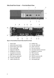
.... power connector 15. line-out connector 16. line-in/microphone connector 17. DisplayPort connector 18. drive activity light 5. Wi-Fi antenna (optional) 10. serial connector 20. USB 2.0 connectors (5) 21. diagnostic lights (4) 6. USB 2.0 connectors (2) 9. link integrity light 4 Front And Back View Figure 4. optical drive 2. padlock ring 13. VGA connector 19. Ultra Small Form Factor...
.... power connector 15. line-out connector 16. line-in/microphone connector 17. DisplayPort connector 18. drive activity light 5. Wi-Fi antenna (optional) 10. serial connector 20. USB 2.0 connectors (5) 21. diagnostic lights (4) 6. USB 2.0 connectors (2) 9. link integrity light 4 Front And Back View Figure 4. optical drive 2. padlock ring 13. VGA connector 19. Ultra Small Form Factor...
User Manual
Page 5
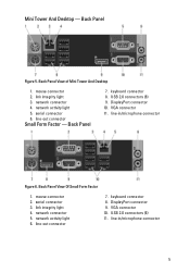
keyboard connector 8. DisplayPort connector 10. network connector 4. line-out connector Small Form Factor - VGA connector 11. line-in /microphone connector 5 link integrity light 4. network activity light 6. USB 2.0 connectors (6) 11. Back Panel Figure 5. Back Panel View of Mini Tower And Desktop 1. Back Panel 7. line-out connector 7. keyboard connector 8. mouse connector 2. VGA connector ...
keyboard connector 8. DisplayPort connector 10. network connector 4. line-out connector Small Form Factor - VGA connector 11. line-in /microphone connector 5 link integrity light 4. network activity light 6. USB 2.0 connectors (6) 11. Back Panel Figure 5. Back Panel View of Mini Tower And Desktop 1. Back Panel 7. line-out connector 7. keyboard connector 8. mouse connector 2. VGA connector ...
User Manual
Page 10
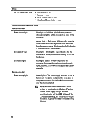
... drive bays • Mini Tower - one Control Lights And Diagnostic Lights Front of the computer. Blinking blue light indicates that the computer is functional. For more information on and is reading data from or writing data to the power connector (at support.dell.com/ manuals. one • Small Form Factor ...- The power supply is turned on the diagnostic lights, see the Service Manual at the back of the power system by pressing the test ...
... drive bays • Mini Tower - one Control Lights And Diagnostic Lights Front of the computer. Blinking blue light indicates that the computer is functional. For more information on and is reading data from or writing data to the power connector (at support.dell.com/ manuals. one • Small Form Factor ...- The power supply is turned on the diagnostic lights, see the Service Manual at the back of the power system by pressing the test ...
Technical Guide
Page 3
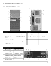
DELL™ OPTIPLEX™ 990 TECHNICAL GUIDEBOOK -V 1.0 MINI TOWER COMPUTER (MT) VIEW FRONT VIEW BACK VIEW 1 Power Button, Power Light 6 Optical Drive (optional) 10 Power Supply Diagnostic 14 Expansion Card Slots(4) Light 2 Optical Drive Bay (optional) 3 Headphone Connector 4 Microphone Connector 7 Optical Drive Eject Button 8 USB 2.0 Connectors (4) 9 Drive Activity Light 11 Power Supply Diagnostic 15 Security Cable Slot...
DELL™ OPTIPLEX™ 990 TECHNICAL GUIDEBOOK -V 1.0 MINI TOWER COMPUTER (MT) VIEW FRONT VIEW BACK VIEW 1 Power Button, Power Light 6 Optical Drive (optional) 10 Power Supply Diagnostic 14 Expansion Card Slots(4) Light 2 Optical Drive Bay (optional) 3 Headphone Connector 4 Microphone Connector 7 Optical Drive Eject Button 8 USB 2.0 Connectors (4) 9 Drive Activity Light 11 Power Supply Diagnostic 15 Security Cable Slot...
Technical Guide
Page 5
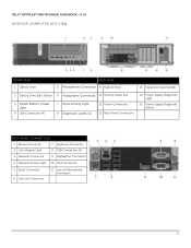
DELL™ OPTIPLEX™ 990 TECHNICAL GUIDEBOOK -V 1.0 DESKTOP COMPUTER (DT) VIEW FRONT VIEW 1 Optical Drive BACK VIEW 5 Microphone Connector 9 Padlock Ring 13 Expansion Card Slots(4) 2 Optical Drive Eject Button 6 Headphone Connector 10 Security Cable Slot 3 Power Button, Power Light 4 USB Connectors (4) 7 Drive Activity Light 8 Diagnostic Lights (4) 11 Power Connectors 12 Back Panel Connectors 14 Power Supply Diagnostic...
DELL™ OPTIPLEX™ 990 TECHNICAL GUIDEBOOK -V 1.0 DESKTOP COMPUTER (DT) VIEW FRONT VIEW 1 Optical Drive BACK VIEW 5 Microphone Connector 9 Padlock Ring 13 Expansion Card Slots(4) 2 Optical Drive Eject Button 6 Headphone Connector 10 Security Cable Slot 3 Power Button, Power Light 4 USB Connectors (4) 7 Drive Activity Light 8 Diagnostic Lights (4) 11 Power Connectors 12 Back Panel Connectors 14 Power Supply Diagnostic...
Technical Guide
Page 7
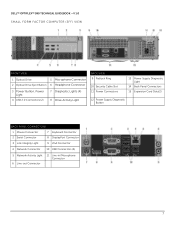
DELL™ OPTIPLEX™ 990 TECHNICAL GUIDEBOOK -V 1.0 SMALL FORM FACTOR COMPUTER (SFF) VIEW FRONT VIEW 1 Optical Drive 5 Microphone Connector 2 Optical Drive Eject Button 6 Headphone Connector 3 Power Button, Power Light 4 USB 2.0 Connectors (2) 7 Diagnostic Lights (4) 8 Drive Activity Light BACK VIEW 9 Padlock Ring 10 Security Cable Slot 11 Power Connectors 13 Power Supply Diagnostic Light 14 Back Panel Connectors 15 Expansion...
DELL™ OPTIPLEX™ 990 TECHNICAL GUIDEBOOK -V 1.0 SMALL FORM FACTOR COMPUTER (SFF) VIEW FRONT VIEW 1 Optical Drive 5 Microphone Connector 2 Optical Drive Eject Button 6 Headphone Connector 3 Power Button, Power Light 4 USB 2.0 Connectors (2) 7 Diagnostic Lights (4) 8 Drive Activity Light BACK VIEW 9 Padlock Ring 10 Security Cable Slot 11 Power Connectors 13 Power Supply Diagnostic Light 14 Back Panel Connectors 15 Expansion...
Technical Guide
Page 9
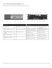
DELL™ OPTIPLEX™ 990 TECHNICAL GUIDEBOOK -V 1.0 ULTRA SMALL FORM FACTOR COMPUTER (USFF) VIEW FRONT VIEW 1 Optical Drive 2 Optical Drive Eject Button 3 Power Button, Power Light 4 Drive Activity Light 5 Diagnostic Lights (4) 6 Headphone Connector 7 Microphone Connector 8 USB Connectors (2) BACK VIEW 10 Wi-Fi Antenna (optional) 17 Line-in/ Microphone Connector 11 Network Activity Light 18 DisplayPort Connector 12 Captive...
DELL™ OPTIPLEX™ 990 TECHNICAL GUIDEBOOK -V 1.0 ULTRA SMALL FORM FACTOR COMPUTER (USFF) VIEW FRONT VIEW 1 Optical Drive 2 Optical Drive Eject Button 3 Power Button, Power Light 4 Drive Activity Light 5 Diagnostic Lights (4) 6 Headphone Connector 7 Microphone Connector 8 USB Connectors (2) BACK VIEW 10 Wi-Fi Antenna (optional) 17 Line-in/ Microphone Connector 11 Network Activity Light 18 DisplayPort Connector 12 Captive...


