User Manual
Page 4
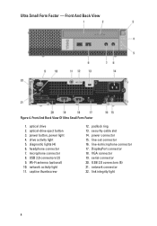
... Small Form Factor 1. power button, power light 4. diagnostic lights (4) 6. headphone connector 7. power connector 15. microphone connector 8. VGA connector 19. security-cable slot 14. USB 2.0 connectors (2) 9. DisplayPort connector 18. USB 2.0 connectors (5) 21. drive activity light 5. line-in/microphone connector 17.
... Small Form Factor 1. power button, power light 4. diagnostic lights (4) 6. headphone connector 7. power connector 15. microphone connector 8. VGA connector 19. security-cable slot 14. USB 2.0 connectors (2) 9. DisplayPort connector 18. USB 2.0 connectors (5) 21. drive activity light 5. line-in/microphone connector 17.
User Manual
Page 5
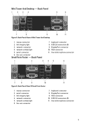
... 10. network connector 5. line-in /microphone connector Figure 6. Back Panel View of Mini Tower And Desktop 1. mouse connector 2. DisplayPort connector 9. mouse connector 2. VGA connector 11. line-in /microphone connector 5 line-out connector 7. USB 2.0 connectors (6) 11. network connector 4. line-out connector Small Form Factor - link ...
... 10. network connector 5. line-in /microphone connector Figure 6. Back Panel View of Mini Tower And Desktop 1. mouse connector 2. DisplayPort connector 9. mouse connector 2. VGA connector 11. line-in /microphone connector 5 line-out connector 7. USB 2.0 connectors (6) 11. network connector 4. line-out connector Small Form Factor - link ...
User Manual
Page 6
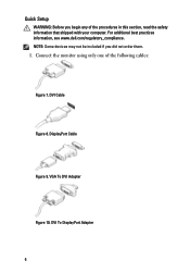
DVI Cable Figure 8. For additional best practices information, see www.dell.com/regulatory_compliance. VGA To DVI Adapter Figure 10. DVI To DisplayPort Adapter 6 Connect the monitor using only one of the procedures in this section, read the safety information that shipped with your computer. NOTE: Some devices may not be included if you begin any of the following cables: Figure 7. Quick Setup WARNING: Before you did not order them. 1. DisplayPort Cable Figure 9.
DVI Cable Figure 8. For additional best practices information, see www.dell.com/regulatory_compliance. VGA To DVI Adapter Figure 10. DVI To DisplayPort Adapter 6 Connect the monitor using only one of the procedures in this section, read the safety information that shipped with your computer. NOTE: Some devices may not be included if you begin any of the following cables: Figure 7. Quick Setup WARNING: Before you did not order them. 1. DisplayPort Cable Figure 9.

User Manual
Page 7
Connect the USB keyboard or mouse (optional). Connect the power cable(s). 7 Figure 14. USB Connection 3. Connect the modem (optional). Network Connection 4. Modem Connection 5. Figure 11. Figure 12. Connect the network cable (optional). Figure 13. VGA To DisplayPort Adapter 2.
Connect the USB keyboard or mouse (optional). Connect the power cable(s). 7 Figure 14. USB Connection 3. Connect the modem (optional). Network Connection 4. Modem Connection 5. Figure 11. Figure 12. Connect the network cable (optional). Figure 13. VGA To DisplayPort Adapter 2.
Technical Guide
Page 3
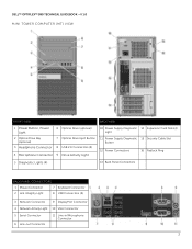
DELL™ OPTIPLEX™ 990 TECHNICAL GUIDEBOOK -V 1.0 MINI TOWER COMPUTER (MT) VIEW FRONT VIEW BACK VIEW 1 Power Button, Power Light 6 Optical Drive (optional) 10 Power Supply Diagnostic 14 Expansion Card ... Power Connectors 16 Padlock Ring 5 Diagnostic Lights (4) 13 Back Panel Connectors BACK PANEL CONNECTORS 1 Mouse Connector 7 Keyboard Connector 2 Link Integrity Light 8 USB Connectors (6) 3 Network Connector 9 DisplayPort Connector 4 Network Activity Light 10 VGA Connector 5 Serial Connector 6 Line-out Connector 11 Line-in/Microphone Connector 3
DELL™ OPTIPLEX™ 990 TECHNICAL GUIDEBOOK -V 1.0 MINI TOWER COMPUTER (MT) VIEW FRONT VIEW BACK VIEW 1 Power Button, Power Light 6 Optical Drive (optional) 10 Power Supply Diagnostic 14 Expansion Card ... Power Connectors 16 Padlock Ring 5 Diagnostic Lights (4) 13 Back Panel Connectors BACK PANEL CONNECTORS 1 Mouse Connector 7 Keyboard Connector 2 Link Integrity Light 8 USB Connectors (6) 3 Network Connector 9 DisplayPort Connector 4 Network Activity Light 10 VGA Connector 5 Serial Connector 6 Line-out Connector 11 Line-in/Microphone Connector 3
Technical Guide
Page 5
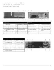
DELL™ OPTIPLEX™ 990 TECHNICAL GUIDEBOOK -V 1.0 DESKTOP COMPUTER (DT) VIEW FRONT VIEW 1 Optical Drive BACK VIEW 5 Microphone Connector 9 Padlock Ring 13 Expansion Card Slots(4) 2 Optical Drive Eject Button 6 Headphone ... Connectors 14 Power Supply Diagnostic Light 15 Power Supply Diagnostic Button BACK PANEL CONNECTORS 1 Mouse Connector 7 Keyboard Connector 2 Link Integrity Light 8 USB Connectors (6) 3 Network Connector 9 DisplayPort Connector 4 Network Activity Light 10 VGA Connector 5 Serial Connector 6 Line-out Connector 11 Line-in/Microphone Connector 5
DELL™ OPTIPLEX™ 990 TECHNICAL GUIDEBOOK -V 1.0 DESKTOP COMPUTER (DT) VIEW FRONT VIEW 1 Optical Drive BACK VIEW 5 Microphone Connector 9 Padlock Ring 13 Expansion Card Slots(4) 2 Optical Drive Eject Button 6 Headphone ... Connectors 14 Power Supply Diagnostic Light 15 Power Supply Diagnostic Button BACK PANEL CONNECTORS 1 Mouse Connector 7 Keyboard Connector 2 Link Integrity Light 8 USB Connectors (6) 3 Network Connector 9 DisplayPort Connector 4 Network Activity Light 10 VGA Connector 5 Serial Connector 6 Line-out Connector 11 Line-in/Microphone Connector 5
Technical Guide
Page 7
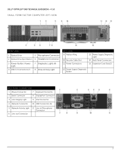
DELL™ OPTIPLEX™ 990 TECHNICAL GUIDEBOOK -V 1.0 SMALL FORM FACTOR COMPUTER (SFF) VIEW FRONT VIEW 1 Optical Drive 5 Microphone Connector 2 Optical Drive Eject Button 6 Headphone Connector 3 Power Button, Power Light 4...Light 14 Back Panel Connectors 15 Expansion Card Slots(2) 12 Power Supply Diagnostic Button BACK PANEL CONNECTORS 1 Mouse Connector 7 Keyboard Connector 2 Serial Connector 8 DisplayPort Connector 3 Link Integrity Light 9 VGA Connector 4 Network Connector 10 USB Connectors (6) 5 Network Activity Light 6 Line-out Connector 11 Line-in/Microphone Connector 7
DELL™ OPTIPLEX™ 990 TECHNICAL GUIDEBOOK -V 1.0 SMALL FORM FACTOR COMPUTER (SFF) VIEW FRONT VIEW 1 Optical Drive 5 Microphone Connector 2 Optical Drive Eject Button 6 Headphone Connector 3 Power Button, Power Light 4...Light 14 Back Panel Connectors 15 Expansion Card Slots(2) 12 Power Supply Diagnostic Button BACK PANEL CONNECTORS 1 Mouse Connector 7 Keyboard Connector 2 Serial Connector 8 DisplayPort Connector 3 Link Integrity Light 9 VGA Connector 4 Network Connector 10 USB Connectors (6) 5 Network Activity Light 6 Line-out Connector 11 Line-in/Microphone Connector 7
Technical Guide
Page 9
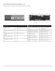
DELL™ OPTIPLEX™ 990 TECHNICAL GUIDEBOOK -V 1.0 ULTRA SMALL FORM FACTOR COMPUTER (USFF) VIEW FRONT VIEW 1 Optical Drive 2 Optical Drive Eject Button 3 Power Button, Power Light 4 ...Drive Activity Light 5 Diagnostic Lights (4) 6 Headphone Connector 7 Microphone Connector 8 USB Connectors (2) BACK VIEW 10 Wi-Fi Antenna (optional) 17 Line-in/ Microphone Connector 11 Network Activity Light 18 DisplayPort...
DELL™ OPTIPLEX™ 990 TECHNICAL GUIDEBOOK -V 1.0 ULTRA SMALL FORM FACTOR COMPUTER (USFF) VIEW FRONT VIEW 1 Optical Drive 2 Optical Drive Eject Button 3 Power Button, Power Light 4 ...Drive Activity Light 5 Diagnostic Lights (4) 6 Headphone Connector 7 Microphone Connector 8 USB Connectors (2) BACK VIEW 10 Wi-Fi Antenna (optional) 17 Line-in/ Microphone Connector 11 Network Activity Light 18 DisplayPort...
Technical Guide
Page 16
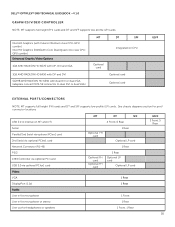
...Serial via optional PCIex1 card Network Connector (RJ-45) PS/2 1394 Controller via optional PCI card USB 3.0 via optional PCIex1 card Video: VGA DisplayPort (1.1a) Audio: Line in for microphone Line in for microphone or stereo Line out for port/ connector locations USB 2.0 (1 internal on CPU... USFF EXTERNAL PORTS/CONNECTORS NOTE: MT supports full height (FH) cards and DT and SFF supports low profile (LP) cards. DELL™ OPTIPLEX™ 990 TECHNICAL GUIDEBOOK -V 1.0 GRAPHICS/VIDEO CONTROLLER NOTE: MT supports full height (FH) cards and DT and SFF supports low profile (LP) cards....
...Serial via optional PCIex1 card Network Connector (RJ-45) PS/2 1394 Controller via optional PCI card USB 3.0 via optional PCIex1 card Video: VGA DisplayPort (1.1a) Audio: Line in for microphone Line in for microphone or stereo Line out for port/ connector locations USB 2.0 (1 internal on CPU... USFF EXTERNAL PORTS/CONNECTORS NOTE: MT supports full height (FH) cards and DT and SFF supports low profile (LP) cards. DELL™ OPTIPLEX™ 990 TECHNICAL GUIDEBOOK -V 1.0 GRAPHICS/VIDEO CONTROLLER NOTE: MT supports full height (FH) cards and DT and SFF supports low profile (LP) cards....
Technical Guide
Page 28
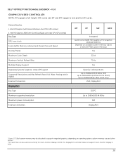
... Systems Graphics/ Video API Support Supported Resolutions and Max Refresh Rates (Hz) (Note: Analog and/or digital) External Connectors DisplayPort Bus Type Maximum supported resolution Maximum power consumption External connectors MT DT SFF USFF Integrated Gen6 Core Intel® HD Graphics /... on available system memory (Up to 1.7GB with Celeron/Pentium class CPU-GPU combo] 2. The DisplayPort controller does not support multi-monitor display in DOS. DELL™ OPTIPLEX™ 990 TECHNICAL GUIDEBOOK -V 1.0 GRAPHICS/VIDEO CONTROLLER NOTE: MT supports full height (FH) cards and DT and...
... Systems Graphics/ Video API Support Supported Resolutions and Max Refresh Rates (Hz) (Note: Analog and/or digital) External Connectors DisplayPort Bus Type Maximum supported resolution Maximum power consumption External connectors MT DT SFF USFF Integrated Gen6 Core Intel® HD Graphics /... on available system memory (Up to 1.7GB with Celeron/Pentium class CPU-GPU combo] 2. The DisplayPort controller does not support multi-monitor display in DOS. DELL™ OPTIPLEX™ 990 TECHNICAL GUIDEBOOK -V 1.0 GRAPHICS/VIDEO CONTROLLER NOTE: MT supports full height (FH) cards and DT and...
Technical Guide
Page 29
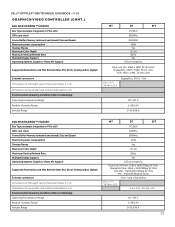
DELL™ OPTIPLEX™ 990 TECHNICAL GUIDEBOOK -V 1.0 GRAPHICS/VIDEO CONTROLLER (CONT.) 1GB AMD RADEON™ HD6670 Bus Type (example integrated...bit 85Hz Yes D3D and OpenGL Dual-Link DVI: 2560 x 1600, 32-bit color DisplayPort: 2560 x 1600, 32-bit color VGA: 1920 x 1440, 32-bits color 6.6 x 4.7 / 16.764 x 12.0 DisplayPort, DVI-D, VGA 10°-50° C 5-90% RH 0-20,000 ft. ... Max: 2560 x 1600/32bpp @ 75Hz VGA Max : 1920x1440/32bpp @ 75Hz Min : 640x480/8bpp @ 60Hz 1 DVI-I and 1 DisplayPort 6.6 x 4.7 / 16.764 x 12.0 6.6 x 3.35 / 16.764 x 8.5 10°-50° C 5-90% RH 0-20,000 ft. 29
DELL™ OPTIPLEX™ 990 TECHNICAL GUIDEBOOK -V 1.0 GRAPHICS/VIDEO CONTROLLER (CONT.) 1GB AMD RADEON™ HD6670 Bus Type (example integrated...bit 85Hz Yes D3D and OpenGL Dual-Link DVI: 2560 x 1600, 32-bit color DisplayPort: 2560 x 1600, 32-bit color VGA: 1920 x 1440, 32-bits color 6.6 x 4.7 / 16.764 x 12.0 DisplayPort, DVI-D, VGA 10°-50° C 5-90% RH 0-20,000 ft. ... Max: 2560 x 1600/32bpp @ 75Hz VGA Max : 1920x1440/32bpp @ 75Hz Min : 640x480/8bpp @ 60Hz 1 DVI-I and 1 DisplayPort 6.6 x 4.7 / 16.764 x 12.0 6.6 x 3.35 / 16.764 x 8.5 10°-50° C 5-90% RH 0-20,000 ft. 29


