User Manual
Page 1
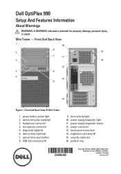
...-drive bay (optional) 3. Front And Back View Of Mini Tower 1. drive activity light 10. power supply diagnostic light 11. power supply diagnostic button 12. security-cable slot 16. back panel connectors 14. ...2011 headphone connector 4. optical-drive eject button 8. microphone connector 5. diagnostic lights (4) 6. Mini Tower - USB 2.0 connectors (4) 9. power connector 13. expansion-card slots (4) 15. optical drive (optional) 7. Front And Back View Figure 1. Dell OptiPlex 990 Setup And Features Information About Warnings WARNING: A WARNING indicates a potential ...
...-drive bay (optional) 3. Front And Back View Of Mini Tower 1. drive activity light 10. power supply diagnostic light 11. power supply diagnostic button 12. security-cable slot 16. back panel connectors 14. ...2011 headphone connector 4. optical-drive eject button 8. microphone connector 5. diagnostic lights (4) 6. Mini Tower - USB 2.0 connectors (4) 9. power connector 13. expansion-card slots (4) 15. optical drive (optional) 7. Front And Back View Figure 1. Dell OptiPlex 990 Setup And Features Information About Warnings WARNING: A WARNING indicates a potential ...
User Manual
Page 2
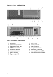
Front And Back View Of Desktop 1. USB 2.0 connectors (4) 5. diagnostic lights (4) 9. back panel connectors 13. power supply diagnostic light 15. microphone connector 6. power button, power light 4. expansion-card slots (4) 14. optical-drive eject button 3. security-cable slot 11. power connector 12. drive activity light 8. Desktop - Front And Back View Figure 2. padlock ring 10. power supply diagnostic button 2 headphone connector 7. optical drive 2.
Front And Back View Of Desktop 1. USB 2.0 connectors (4) 5. diagnostic lights (4) 9. back panel connectors 13. power supply diagnostic light 15. microphone connector 6. power button, power light 4. expansion-card slots (4) 14. optical-drive eject button 3. security-cable slot 11. power connector 12. drive activity light 8. Desktop - Front And Back View Figure 2. padlock ring 10. power supply diagnostic button 2 headphone connector 7. optical drive 2.
User Manual
Page 3
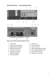
optical drive 2. USB 2.0 connectors (4) 5. diagnostic lights (4) 8. back panel connectors 15. Front And Back View Of Small Form Factor 1. drive activity light 9. padlock ring 10. power supply diagnostic light 14. power button, power light 4. security-cable slot 11. power connector 12. headphone connector 7. expansion-card slots (2) 3 power supply diagnostic button 13. Small Form Factor - Front And Back View Figure 3. optical-drive eject button 3. microphone connector 6.
optical drive 2. USB 2.0 connectors (4) 5. diagnostic lights (4) 8. back panel connectors 15. Front And Back View Of Small Form Factor 1. drive activity light 9. padlock ring 10. power supply diagnostic light 14. power button, power light 4. security-cable slot 11. power connector 12. headphone connector 7. expansion-card slots (2) 3 power supply diagnostic button 13. Small Form Factor - Front And Back View Figure 3. optical-drive eject button 3. microphone connector 6.
User Manual
Page 4
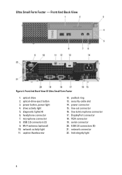
... Form Factor 1. Wi-Fi antenna (optional) 10. captive thumbscrew 12. line-in/microphone connector 17. network connector 22. Front And Back View Figure 4. drive activity light 5. network activity light 11. DisplayPort connector 18. USB 2.0 connectors (2) 9. padlock ring 13. diagnostic lights (4) 6. power button, power light 4. power connector 15. microphone connector 8. VGA connector 19. link integrity...
... Form Factor 1. Wi-Fi antenna (optional) 10. captive thumbscrew 12. line-in/microphone connector 17. network connector 22. Front And Back View Figure 4. drive activity light 5. network activity light 11. DisplayPort connector 18. USB 2.0 connectors (2) 9. padlock ring 13. diagnostic lights (4) 6. power button, power light 4. power connector 15. microphone connector 8. VGA connector 19. link integrity...
User Manual
Page 5
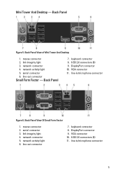
DisplayPort connector 10. serial connector 6. Back Panel 7. link integrity light 4. keyboard connector 8. USB 2.0 connectors (6) 11. mouse connector 2. link integrity light 3. network connector 5. Back Panel View of Mini Tower And Desktop 1. line-in /microphone ... And Desktop - VGA connector 11. VGA connector 10. USB 2.0 connectors (6) 9. serial connector 3. network activity light 5. keyboard connector 8. line-out connector Small Form Factor - mouse connector 2. line-out connector 7. DisplayPort connector 9. Back Panel Figure 5. network ...
DisplayPort connector 10. serial connector 6. Back Panel 7. link integrity light 4. keyboard connector 8. USB 2.0 connectors (6) 11. mouse connector 2. link integrity light 3. network connector 5. Back Panel View of Mini Tower And Desktop 1. line-in /microphone ... And Desktop - VGA connector 11. VGA connector 10. USB 2.0 connectors (6) 9. serial connector 3. network activity light 5. keyboard connector 8. line-out connector Small Form Factor - mouse connector 2. line-out connector 7. DisplayPort connector 9. Back Panel Figure 5. network ...
User Manual
Page 10
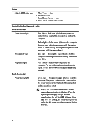
... For more information on the front panel of the computer. NOTE: You can test the health of computer Power supply light Green light - one Control Lights And Diagnostic Lights Front of the computer) and the electrical outlet. The power supply is reading data from or writing data to the ...power connector (at support.dell.com/ manuals. one • Small Form Factor - Solid blue light indicates power-on and is within specification, the self-test LED lights up , the power supply may be connected to the hard drive. Solid ...
... For more information on the front panel of the computer. NOTE: You can test the health of computer Power supply light Green light - one Control Lights And Diagnostic Lights Front of the computer) and the electrical outlet. The power supply is reading data from or writing data to the ...power connector (at support.dell.com/ manuals. one • Small Form Factor - Solid blue light indicates power-on and is within specification, the self-test LED lights up , the power supply may be connected to the hard drive. Solid ...
Technical Guide
Page 3
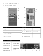
DELL™ OPTIPLEX™ 990 TECHNICAL GUIDEBOOK -V 1.0 MINI TOWER COMPUTER (MT) VIEW FRONT VIEW BACK VIEW 1 Power Button, Power Light 6 Optical Drive (optional) 10 Power Supply Diagnostic 14 Expansion Card Slots(4) Light 2 Optical Drive Bay (optional) 3 Headphone Connector 4 Microphone Connector 7 Optical Drive Eject Button 8 USB 2.0 Connectors (4) 9 Drive Activity Light 11 Power Supply Diagnostic 15 Security Cable Slot...
DELL™ OPTIPLEX™ 990 TECHNICAL GUIDEBOOK -V 1.0 MINI TOWER COMPUTER (MT) VIEW FRONT VIEW BACK VIEW 1 Power Button, Power Light 6 Optical Drive (optional) 10 Power Supply Diagnostic 14 Expansion Card Slots(4) Light 2 Optical Drive Bay (optional) 3 Headphone Connector 4 Microphone Connector 7 Optical Drive Eject Button 8 USB 2.0 Connectors (4) 9 Drive Activity Light 11 Power Supply Diagnostic 15 Security Cable Slot...
Technical Guide
Page 5
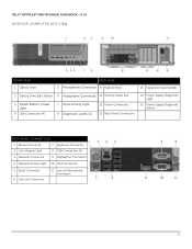
DELL™ OPTIPLEX™ 990 TECHNICAL GUIDEBOOK -V 1.0 DESKTOP COMPUTER (DT) VIEW FRONT VIEW 1 Optical Drive BACK VIEW 5 Microphone Connector 9 Padlock Ring 13 Expansion Card Slots(4) 2 Optical Drive Eject Button 6 Headphone Connector 10 Security Cable Slot 3 Power Button, Power Light 4 USB Connectors (4) 7 Drive Activity Light 8 Diagnostic Lights (4) 11 Power Connectors 12 Back Panel Connectors 14 Power Supply Diagnostic...
DELL™ OPTIPLEX™ 990 TECHNICAL GUIDEBOOK -V 1.0 DESKTOP COMPUTER (DT) VIEW FRONT VIEW 1 Optical Drive BACK VIEW 5 Microphone Connector 9 Padlock Ring 13 Expansion Card Slots(4) 2 Optical Drive Eject Button 6 Headphone Connector 10 Security Cable Slot 3 Power Button, Power Light 4 USB Connectors (4) 7 Drive Activity Light 8 Diagnostic Lights (4) 11 Power Connectors 12 Back Panel Connectors 14 Power Supply Diagnostic...
Technical Guide
Page 7
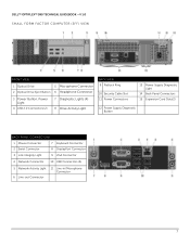
DELL™ OPTIPLEX™ 990 TECHNICAL GUIDEBOOK -V 1.0 SMALL FORM FACTOR COMPUTER (SFF) VIEW FRONT VIEW 1 Optical Drive 5 Microphone Connector 2 Optical Drive Eject Button 6 Headphone Connector 3 Power Button, Power Light 4 USB 2.0 Connectors (2) 7 Diagnostic Lights (4) 8 Drive Activity Light BACK VIEW 9 Padlock Ring 10 Security Cable Slot 11 Power Connectors 13 Power Supply Diagnostic Light 14 Back Panel Connectors 15 Expansion...
DELL™ OPTIPLEX™ 990 TECHNICAL GUIDEBOOK -V 1.0 SMALL FORM FACTOR COMPUTER (SFF) VIEW FRONT VIEW 1 Optical Drive 5 Microphone Connector 2 Optical Drive Eject Button 6 Headphone Connector 3 Power Button, Power Light 4 USB 2.0 Connectors (2) 7 Diagnostic Lights (4) 8 Drive Activity Light BACK VIEW 9 Padlock Ring 10 Security Cable Slot 11 Power Connectors 13 Power Supply Diagnostic Light 14 Back Panel Connectors 15 Expansion...
Technical Guide
Page 9
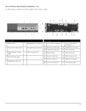
DELL™ OPTIPLEX™ 990 TECHNICAL GUIDEBOOK -V 1.0 ULTRA SMALL FORM FACTOR COMPUTER (USFF) VIEW FRONT VIEW 1 Optical Drive 2 Optical Drive Eject Button 3 Power Button, Power Light 4 Drive Activity Light 5 Diagnostic Lights (4) 6 Headphone Connector 7 Microphone Connector 8 USB Connectors (2) BACK VIEW 10 Wi-Fi Antenna (optional) 17 Line-in/ Microphone Connector 11 Network Activity Light 18 DisplayPort Connector 12 Captive...
DELL™ OPTIPLEX™ 990 TECHNICAL GUIDEBOOK -V 1.0 ULTRA SMALL FORM FACTOR COMPUTER (USFF) VIEW FRONT VIEW 1 Optical Drive 2 Optical Drive Eject Button 3 Power Button, Power Light 4 Drive Activity Light 5 Diagnostic Lights (4) 6 Headphone Connector 7 Microphone Connector 8 USB Connectors (2) BACK VIEW 10 Wi-Fi Antenna (optional) 17 Line-in/ Microphone Connector 11 Network Activity Light 18 DisplayPort Connector 12 Captive...


