User Manual
Page 1
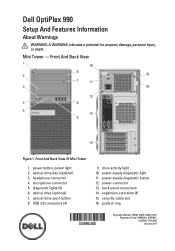
Dell OptiPlex 990 Setup And Features Information About Warnings WARNING: A WARNING indicates a potential for property damage, personal injury, or death. Front And Back View Figure 1. Front And Back View Of Mini Tower 1. microphone connector 5. USB 2.0 connectors (4) 9. back panel connectors 14. power button, power light 2. diagnostic lights (4) 6. power supply diagnostic light 11. Mini Tower - headphone connector 4. drive activity light 10. power supply diagnostic button 12. padlock ring Regulatory Model: D09M, D05D, D03S, D01U Regulatory Type: D09M001, D05D001, ...
Dell OptiPlex 990 Setup And Features Information About Warnings WARNING: A WARNING indicates a potential for property damage, personal injury, or death. Front And Back View Figure 1. Front And Back View Of Mini Tower 1. microphone connector 5. USB 2.0 connectors (4) 9. back panel connectors 14. power button, power light 2. diagnostic lights (4) 6. power supply diagnostic light 11. Mini Tower - headphone connector 4. drive activity light 10. power supply diagnostic button 12. padlock ring Regulatory Model: D09M, D05D, D03S, D01U Regulatory Type: D09M001, D05D001, ...
User Manual
Page 3
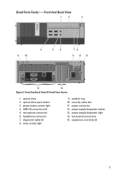
microphone connector 6. headphone connector 7. power connector 12. back panel connectors 15. Front And Back View Of Small Form Factor 1. power supply diagnostic light 14. Front And Back View Figure 3. optical drive 2. power button, power light 4. USB 2.0 connectors (4) 5. expansion-card slots (2) 3 optical-drive eject button 3. security-cable slot 11. power supply diagnostic button 13. diagnostic lights (4) 8. drive activity light 9. Small Form Factor - padlock ring 10.
microphone connector 6. headphone connector 7. power connector 12. back panel connectors 15. Front And Back View Of Small Form Factor 1. power supply diagnostic light 14. Front And Back View Figure 3. optical drive 2. power button, power light 4. USB 2.0 connectors (4) 5. expansion-card slots (2) 3 optical-drive eject button 3. security-cable slot 11. power supply diagnostic button 13. diagnostic lights (4) 8. drive activity light 9. Small Form Factor - padlock ring 10.

User Manual
Page 7
VGA To DisplayPort Adapter 2. Connect the USB keyboard or mouse (optional). Connect the network cable (optional). Figure 12. USB Connection 3. Figure 13. Network Connection 4. Connect the power cable(s). 7 Figure 14. Connect the modem (optional). Modem Connection 5. Figure 11.
VGA To DisplayPort Adapter 2. Connect the USB keyboard or mouse (optional). Connect the network cable (optional). Figure 12. USB Connection 3. Figure 13. Network Connection 4. Connect the power cable(s). 7 Figure 14. Connect the modem (optional). Modem Connection 5. Figure 11.
User Manual
Page 10
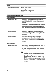
one Control Lights And Diagnostic Lights Front of the computer. Solid blue light indicates power-on and is functional. Solid amber light when the computer does not start indicates a problem with the system board. Drive activity light Blue light - When the system power supply voltage is reading data from or writing data to the power connector (at support.dell.com/ manuals. AC power must be connected to the hard drive. one • Ultra Small...
one Control Lights And Diagnostic Lights Front of the computer. Solid blue light indicates power-on and is functional. Solid amber light when the computer does not start indicates a problem with the system board. Drive activity light Blue light - When the system power supply voltage is reading data from or writing data to the power connector (at support.dell.com/ manuals. AC power must be connected to the hard drive. one • Ultra Small...
System Board Mode Configuration
Page 2
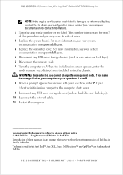
... number is important for contact information). 2 Note the large mode number on support.dell.com. 4 Replace the computer cover. Printed in any USB mass storage devices (such as hard drives or flash keys). 10 Reconnect the network cable. 11 Restart the computer. PRELIMINARY 3/7/11 - FILE LOCATION: C:\Projects\aa_Working\iAMT Guide\iAMT7\R418K\body.fm NOTE: If the original configuration-mode label is damaged, or otherwise illegible, contact Dell to change the management mode...
... number is important for contact information). 2 Note the large mode number on support.dell.com. 4 Replace the computer cover. Printed in any USB mass storage devices (such as hard drives or flash keys). 10 Reconnect the network cable. 11 Restart the computer. PRELIMINARY 3/7/11 - FILE LOCATION: C:\Projects\aa_Working\iAMT Guide\iAMT7\R418K\body.fm NOTE: If the original configuration-mode label is damaged, or otherwise illegible, contact Dell to change the management mode...
Technical Guide
Page 2
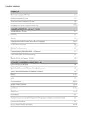
...) View MARKETING SYSTEM CONFIGURATIONS Operating System, Chipset Processor Memory Drives and Removable Storage, System Board Connectors Graphics/Video Controller External Ports/Connectors Communications-Network Adapter (NIC), Wireless Audio and Speakers, Keyboard and Mouse Security, Service and Support, Software DETAILED ENGINEERING SPECIFICATIONS System Dimensions (Physical) System Board Connector Maximum Allowable Dimensions System Level Environmental and Operating Conditions Power Audio Communications Graphics/Video Controller Hard Drives Optical Drive BIOS Defaults Chassis Enclosure and...
...) View MARKETING SYSTEM CONFIGURATIONS Operating System, Chipset Processor Memory Drives and Removable Storage, System Board Connectors Graphics/Video Controller External Ports/Connectors Communications-Network Adapter (NIC), Wireless Audio and Speakers, Keyboard and Mouse Security, Service and Support, Software DETAILED ENGINEERING SPECIFICATIONS System Dimensions (Physical) System Board Connector Maximum Allowable Dimensions System Level Environmental and Operating Conditions Power Audio Communications Graphics/Video Controller Hard Drives Optical Drive BIOS Defaults Chassis Enclosure and...
Technical Guide
Page 3
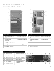
DELL™ OPTIPLEX™ 990 TECHNICAL GUIDEBOOK -V 1.0 MINI TOWER COMPUTER (MT) VIEW FRONT VIEW BACK VIEW 1 Power Button, Power Light 6 Optical Drive (optional) 10 Power Supply Diagnostic 14 Expansion Card Slots(4) Light 2 Optical Drive Bay (optional) 3 Headphone Connector 4 Microphone Connector 7 Optical Drive Eject Button 8 USB 2.0 Connectors (4) 9 Drive Activity Light 11 Power Supply Diagnostic 15 Security Cable Slot Button 12 Power Connectors 16 Padlock Ring 5 Diagnostic Lights (4) 13 Back Panel Connectors BACK PANEL CONNECTORS 1 Mouse Connector 7 Keyboard Connector 2 ...
DELL™ OPTIPLEX™ 990 TECHNICAL GUIDEBOOK -V 1.0 MINI TOWER COMPUTER (MT) VIEW FRONT VIEW BACK VIEW 1 Power Button, Power Light 6 Optical Drive (optional) 10 Power Supply Diagnostic 14 Expansion Card Slots(4) Light 2 Optical Drive Bay (optional) 3 Headphone Connector 4 Microphone Connector 7 Optical Drive Eject Button 8 USB 2.0 Connectors (4) 9 Drive Activity Light 11 Power Supply Diagnostic 15 Security Cable Slot Button 12 Power Connectors 16 Padlock Ring 5 Diagnostic Lights (4) 13 Back Panel Connectors BACK PANEL CONNECTORS 1 Mouse Connector 7 Keyboard Connector 2 ...
Technical Guide
Page 4
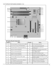
DELL™ OPTIPLEX™ 990 TECHNICAL GUIDEBOOK -V 1.0 MT System Board Components Number Name Number Name 1 Internal Speaker Connector (INT_SPKR) 13 PCI Connector(SLOT3) 2 Front IO Connector (FRONTPANEL) 3 Thermal Sensor Connector(THRM_2) 4 SATA 0 Connector(SATA0) 5 SATA 1 Connector(SATA1) 14 PCI-e 4x Connector(SLOT4) 15 Intrusion Switch Connector (INTRUDER) 16 System Fan Connector (FAN_HDD) 17 P2 Power Connector (12V_PWRCONN) 6 SATA 2 Connector(SATA2) 18 Processor Connector (N/A) 7 SATA 3 Connector(SATA3) 8 Internal USB Connector (INT_USB) 9 Buzzer (BEEP...
DELL™ OPTIPLEX™ 990 TECHNICAL GUIDEBOOK -V 1.0 MT System Board Components Number Name Number Name 1 Internal Speaker Connector (INT_SPKR) 13 PCI Connector(SLOT3) 2 Front IO Connector (FRONTPANEL) 3 Thermal Sensor Connector(THRM_2) 4 SATA 0 Connector(SATA0) 5 SATA 1 Connector(SATA1) 14 PCI-e 4x Connector(SLOT4) 15 Intrusion Switch Connector (INTRUDER) 16 System Fan Connector (FAN_HDD) 17 P2 Power Connector (12V_PWRCONN) 6 SATA 2 Connector(SATA2) 18 Processor Connector (N/A) 7 SATA 3 Connector(SATA3) 8 Internal USB Connector (INT_USB) 9 Buzzer (BEEP...
Technical Guide
Page 5
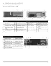
DELL™ OPTIPLEX™ 990 TECHNICAL GUIDEBOOK -V 1.0 DESKTOP COMPUTER (DT) VIEW FRONT VIEW 1 Optical Drive BACK VIEW 5 Microphone Connector 9 Padlock Ring 13 Expansion Card Slots(4) 2 Optical Drive Eject Button 6 Headphone Connector 10 Security Cable Slot 3 Power Button, Power Light 4 USB Connectors (4) 7 Drive Activity Light 8 Diagnostic Lights (4) 11 Power Connectors 12 Back Panel Connectors 14 Power Supply Diagnostic Light 15 Power Supply Diagnostic Button BACK PANEL CONNECTORS 1 Mouse Connector 7 Keyboard Connector 2 Link Integrity Light 8 USB Connectors (6) 3 Network ...
DELL™ OPTIPLEX™ 990 TECHNICAL GUIDEBOOK -V 1.0 DESKTOP COMPUTER (DT) VIEW FRONT VIEW 1 Optical Drive BACK VIEW 5 Microphone Connector 9 Padlock Ring 13 Expansion Card Slots(4) 2 Optical Drive Eject Button 6 Headphone Connector 10 Security Cable Slot 3 Power Button, Power Light 4 USB Connectors (4) 7 Drive Activity Light 8 Diagnostic Lights (4) 11 Power Connectors 12 Back Panel Connectors 14 Power Supply Diagnostic Light 15 Power Supply Diagnostic Button BACK PANEL CONNECTORS 1 Mouse Connector 7 Keyboard Connector 2 Link Integrity Light 8 USB Connectors (6) 3 Network ...
Technical Guide
Page 6
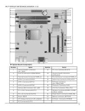
DELL™ OPTIPLEX™ 990 TECHNICAL GUIDEBOOK -V 1.0 DT System Board Components Number Name 1 Internal Speaker Connector (INT_SPKR) 2 Front IO Connector (FRONTPANEL) 3 Thermal Sensor Connector(THRM_2) 4 SATA 0 Connector(SATA0) 5 SATA 1 Connector(SATA1) 6 SATA 2 Connector(SATA2) 7 Internal USB Connector (INT_USB) 8 PCI-e 16x Connector(SLOT1) 9 PCI-e 4x Connector(SLOT4) 10 Buzzer (BEEP) 11 LPC Debug Connector (LPC_DEBUG) 12 PCI Connector(SLOT3) Number Name 13 PCI-e 1x Connector(SLOT2) 14 Intrusion Switch Connector (INTRUDER) 15 Thermal Sensor Connector(...
DELL™ OPTIPLEX™ 990 TECHNICAL GUIDEBOOK -V 1.0 DT System Board Components Number Name 1 Internal Speaker Connector (INT_SPKR) 2 Front IO Connector (FRONTPANEL) 3 Thermal Sensor Connector(THRM_2) 4 SATA 0 Connector(SATA0) 5 SATA 1 Connector(SATA1) 6 SATA 2 Connector(SATA2) 7 Internal USB Connector (INT_USB) 8 PCI-e 16x Connector(SLOT1) 9 PCI-e 4x Connector(SLOT4) 10 Buzzer (BEEP) 11 LPC Debug Connector (LPC_DEBUG) 12 PCI Connector(SLOT3) Number Name 13 PCI-e 1x Connector(SLOT2) 14 Intrusion Switch Connector (INTRUDER) 15 Thermal Sensor Connector(...
Technical Guide
Page 7
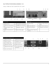
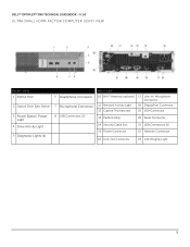
DELL™ OPTIPLEX™ 990 TECHNICAL GUIDEBOOK -V 1.0 SMALL FORM FACTOR COMPUTER (SFF) VIEW FRONT VIEW 1 Optical Drive 5 Microphone Connector 2 Optical Drive Eject Button 6 Headphone Connector 3 Power Button, Power Light 4 USB 2.0 Connectors (2) 7 Diagnostic Lights (4) 8 Drive Activity Light BACK VIEW 9 Padlock Ring 10 Security Cable Slot 11 Power Connectors 13 Power Supply Diagnostic Light 14 Back Panel Connectors 15 Expansion Card Slots(2) 12 Power Supply Diagnostic Button BACK PANEL CONNECTORS 1 Mouse Connector 7 Keyboard Connector 2 Serial Connector 8 DisplayPort ...
DELL™ OPTIPLEX™ 990 TECHNICAL GUIDEBOOK -V 1.0 SMALL FORM FACTOR COMPUTER (SFF) VIEW FRONT VIEW 1 Optical Drive 5 Microphone Connector 2 Optical Drive Eject Button 6 Headphone Connector 3 Power Button, Power Light 4 USB 2.0 Connectors (2) 7 Diagnostic Lights (4) 8 Drive Activity Light BACK VIEW 9 Padlock Ring 10 Security Cable Slot 11 Power Connectors 13 Power Supply Diagnostic Light 14 Back Panel Connectors 15 Expansion Card Slots(2) 12 Power Supply Diagnostic Button BACK PANEL CONNECTORS 1 Mouse Connector 7 Keyboard Connector 2 Serial Connector 8 DisplayPort ...
Technical Guide
Page 8
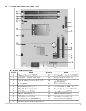
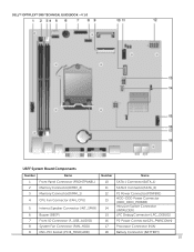
DELL™ OPTIPLEX™ 990 TECHNICAL GUIDEBOOK -V 1.0 SFF System Board Components Number Name 1 P1 power Connector (POWER) 2 System fan Connector (FAN_HDD) 3 Internal Speaker Connector (INT_SPKR) 4 Buzzer (BEEP) 5 PCI-e 4x Connector(SLOT2) 6 PCI-e 16x Connector(SLOT1) 7 SATA 2 Connector(SATA2) 8 SATA 1 Connector(SATA1) 9 SATA 0 Connector(SATA0) 10 Front IO Connector (FRONTPANEL) 11 Intrusion Switch Connector (INTRUDER) Number 12 13 14 15 16 17 18 19 20 21 Name LPC debug Connector (LPC_DEBUG) Battery Connector (BATTERY) P2 Power Connector (12V_PWRCONN) Processor ...
DELL™ OPTIPLEX™ 990 TECHNICAL GUIDEBOOK -V 1.0 SFF System Board Components Number Name 1 P1 power Connector (POWER) 2 System fan Connector (FAN_HDD) 3 Internal Speaker Connector (INT_SPKR) 4 Buzzer (BEEP) 5 PCI-e 4x Connector(SLOT2) 6 PCI-e 16x Connector(SLOT1) 7 SATA 2 Connector(SATA2) 8 SATA 1 Connector(SATA1) 9 SATA 0 Connector(SATA0) 10 Front IO Connector (FRONTPANEL) 11 Intrusion Switch Connector (INTRUDER) Number 12 13 14 15 16 17 18 19 20 21 Name LPC debug Connector (LPC_DEBUG) Battery Connector (BATTERY) P2 Power Connector (12V_PWRCONN) Processor ...
Technical Guide
Page 9
DELL™ OPTIPLEX™ 990 TECHNICAL GUIDEBOOK -V 1.0 ULTRA SMALL FORM FACTOR COMPUTER (USFF) VIEW FRONT VIEW 1 Optical Drive 2 Optical Drive Eject Button 3 Power Button, Power Light 4 Drive Activity Light 5 Diagnostic Lights (4) 6 Headphone Connector 7 Microphone Connector 8 USB Connectors (2) BACK VIEW 10 Wi-Fi Antenna (optional) 17 Line-in/ Microphone Connector 11 Network Activity Light 18 DisplayPort Connector 12 Captive Thumbscrew 19 VGA Connector 13 Padlock Ring 20 Serial Connector 14 Security Cable Slot 21 USB Connectors (5) 15 Power Connector 22 Network Connector 16 ...
DELL™ OPTIPLEX™ 990 TECHNICAL GUIDEBOOK -V 1.0 ULTRA SMALL FORM FACTOR COMPUTER (USFF) VIEW FRONT VIEW 1 Optical Drive 2 Optical Drive Eject Button 3 Power Button, Power Light 4 Drive Activity Light 5 Diagnostic Lights (4) 6 Headphone Connector 7 Microphone Connector 8 USB Connectors (2) BACK VIEW 10 Wi-Fi Antenna (optional) 17 Line-in/ Microphone Connector 11 Network Activity Light 18 DisplayPort Connector 12 Captive Thumbscrew 19 VGA Connector 13 Padlock Ring 20 Serial Connector 14 Security Cable Slot 21 USB Connectors (5) 15 Power Connector 22 Network Connector 16 ...
Technical Guide
Page 10
DELL™ OPTIPLEX™ 990 TECHNICAL GUIDEBOOK -V 1.0 USFF System Board Components Number Name Number Name 1 Front Panel Connector (FRONTPANEL) 10 SATA 1 Connector(SATA_1) 2 Memory Connector(DIMM_2) 11 SATA 0 Connector(SATA_0) 3 Memory Connector(DIMM_1) 12 P1 Power Connector(POWER1) 4 CPU Fan Connector (FAN_CPU) 13 HDD-ODD Power Connector (HDD_ODD_POWER) 5 Internal Speaker Connector (INT_SPKR) 14 Intrusion Switch Connector (INTRUDER) 6 Buzzer (BEEP) 15 LPC Debug Connector (LPC_DEBUG) 7 Front IO Connector (F_USB_AUDIO) 16 P2 Power Connector(12V_PWRCONN) 8...
DELL™ OPTIPLEX™ 990 TECHNICAL GUIDEBOOK -V 1.0 USFF System Board Components Number Name Number Name 1 Front Panel Connector (FRONTPANEL) 10 SATA 1 Connector(SATA_1) 2 Memory Connector(DIMM_2) 11 SATA 0 Connector(SATA_0) 3 Memory Connector(DIMM_1) 12 P1 Power Connector(POWER1) 4 CPU Fan Connector (FAN_CPU) 13 HDD-ODD Power Connector (HDD_ODD_POWER) 5 Internal Speaker Connector (INT_SPKR) 14 Intrusion Switch Connector (INTRUDER) 6 Buzzer (BEEP) 15 LPC Debug Connector (LPC_DEBUG) 7 Front IO Connector (F_USB_AUDIO) 16 P2 Power Connector(12V_PWRCONN) 8...
Technical Guide
Page 14
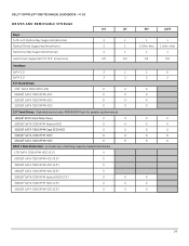
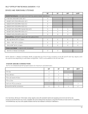
DELL™ OPTIPLEX™ 990 TECHNICAL GUIDEBOOK -V 1.0 DRIVES AND REMOVABLE STORAGE Bays: 5.25-inch Optical Bay Supported (External) Optical Drives Supported (maximum) Hard Drive Bay Supported (Internal) MT DT 2 1 2 1 2 1 Hard Drives Supported 3.5"/2.5" (maximum) 2/2 1/2 Interface: SATA 2.0 SATA 3.0 3.5" Hard Drives: 1TB1 SATA 7200 RPM HDD 500GB1 SATA 7200 RPM HDD 320GB1 SATA 7200 RPM HDD 250GB1 SATA 7200 RPM HDD 2 1 2 2 X X X X X X X X 2.5" Hard Drives: (Hybrid drive includes 4GB NAND Flash for greater performance) 128GB1 SATA Solid State Drive X X 500GB1 ...
DELL™ OPTIPLEX™ 990 TECHNICAL GUIDEBOOK -V 1.0 DRIVES AND REMOVABLE STORAGE Bays: 5.25-inch Optical Bay Supported (External) Optical Drives Supported (maximum) Hard Drive Bay Supported (Internal) MT DT 2 1 2 1 2 1 Hard Drives Supported 3.5"/2.5" (maximum) 2/2 1/2 Interface: SATA 2.0 SATA 3.0 3.5" Hard Drives: 1TB1 SATA 7200 RPM HDD 500GB1 SATA 7200 RPM HDD 320GB1 SATA 7200 RPM HDD 250GB1 SATA 7200 RPM HDD 2 1 2 2 X X X X X X X X 2.5" Hard Drives: (Hybrid drive includes 4GB NAND Flash for greater performance) 128GB1 SATA Solid State Drive X X 500GB1 ...
Technical Guide
Page 15
... SYSTEM BOARD CONNECTORS NOTE: See Detailed Engineering Specifications for maximum card dimensions. PCI Slot PCIe x16 Slot PCIe x16 (wired x4) Slot PCIe x1 Slot Half mini-PCIe connector Serial ATA (SATA) connectors MT DT 1 1 1 1 1 1 1 1 4 3 SFF USFF 1 1 1 3 2 1 For hard drives, GB means 1 billion bytes; actual capacity varies with preloaded material and operating environment and will be less. 2 Discs burned with some existing drives and players; DELL™ OPTIPLEX™ 990 TECHNICAL GUIDEBOOK -V 1.0 DRIVES AND REMOVABLE...
... SYSTEM BOARD CONNECTORS NOTE: See Detailed Engineering Specifications for maximum card dimensions. PCI Slot PCIe x16 Slot PCIe x16 (wired x4) Slot PCIe x1 Slot Half mini-PCIe connector Serial ATA (SATA) connectors MT DT 1 1 1 1 1 1 1 1 4 3 SFF USFF 1 1 1 3 2 1 For hard drives, GB means 1 billion bytes; actual capacity varies with preloaded material and operating environment and will be less. 2 Discs burned with some existing drives and players; DELL™ OPTIPLEX™ 990 TECHNICAL GUIDEBOOK -V 1.0 DRIVES AND REMOVABLE...
Technical Guide
Page 16
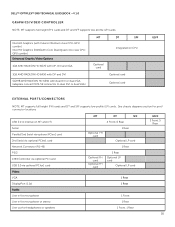
... diagrams section for port/ connector locations USB 2.0 (1 internal on CPU Optional card Optional card Optional card USFF EXTERNAL PORTS/CONNECTORS NOTE: MT supports full height (FH) cards and DT and SFF supports low profile (LP) cards. DELL™ OPTIPLEX™ 990 TECHNICAL GUIDEBOOK -V 1.0 GRAPHICS/VIDEO CONTROLLER NOTE: MT supports full height (FH) cards and DT and SFF supports low profile (LP) cards. Intel HD Graphics [with Celeron/Pentium class CPU-GPU combo] Intel HD Graphics 2000[with iCore Dual/Quad core class CPUGPU combo] Enhanced Graphic/Video Options...
... diagrams section for port/ connector locations USB 2.0 (1 internal on CPU Optional card Optional card Optional card USFF EXTERNAL PORTS/CONNECTORS NOTE: MT supports full height (FH) cards and DT and SFF supports low profile (LP) cards. DELL™ OPTIPLEX™ 990 TECHNICAL GUIDEBOOK -V 1.0 GRAPHICS/VIDEO CONTROLLER NOTE: MT supports full height (FH) cards and DT and SFF supports low profile (LP) cards. Intel HD Graphics [with Celeron/Pentium class CPU-GPU combo] Intel HD Graphics 2000[with iCore Dual/Quad core class CPUGPU combo] Enhanced Graphic/Video Options...
Technical Guide
Page 17
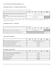
...; 990 TECHNICAL GUIDEBOOK -V 1.0 COMMUNICATIONS - MT Intel® 82579LM Gigabit1 Ethernet LAN 10/100/1000 (Remote Wake Up, PXE support and Intel Active Management Technology support) DT SFF Integrated on system board Optional Optional Optional MT DT SFF USFF Optional Optional Optional Optional Optional 17 MT DT SFF Dell Wireless 1520 PCIe WLAN card (802.11n) Optional card Dell Wireless 1520 half mini-PCIe WLAN card (802.11n) USFF Optional AUDIO AND SPEAKERS Realtek ALC269Q High Definition Audio Codec Internal Dell Business Audio Speaker Dell AX210 2.0 Desktop Speakers...
...; 990 TECHNICAL GUIDEBOOK -V 1.0 COMMUNICATIONS - MT Intel® 82579LM Gigabit1 Ethernet LAN 10/100/1000 (Remote Wake Up, PXE support and Intel Active Management Technology support) DT SFF Integrated on system board Optional Optional Optional MT DT SFF USFF Optional Optional Optional Optional Optional 17 MT DT SFF Dell Wireless 1520 PCIe WLAN card (802.11n) Optional card Dell Wireless 1520 half mini-PCIe WLAN card (802.11n) USFF Optional AUDIO AND SPEAKERS Realtek ALC269Q High Definition Audio Codec Internal Dell Business Audio Speaker Dell AX210 2.0 Desktop Speakers...
Technical Guide
Page 26
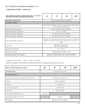
..., Vista 32/64 COMMUNICATIONS - USB 3.0 PORT PCIE ADD-IN CARD Connector Type Controller Details Controller bus architecture (example PCIe 1.0a x1) Chipset IO Ports Power Consumption Connector Full height USB3.0 add-in card Half height USB3.0 add-in card OS Support MT DT SFF PCI Express Gen. 2.0 X1 Optional PCI Express one lane (x1) NEC µPD720200 2 * USB3.0 port Under 30 mA USB 3.0 A Type Optional Win XP, Win Vista and Win 7 USFF 26 DELL™ OPTIPLEX™ 990 TECHNICAL...
..., Vista 32/64 COMMUNICATIONS - USB 3.0 PORT PCIE ADD-IN CARD Connector Type Controller Details Controller bus architecture (example PCIe 1.0a x1) Chipset IO Ports Power Consumption Connector Full height USB3.0 add-in card Half height USB3.0 add-in card OS Support MT DT SFF PCI Express Gen. 2.0 X1 Optional PCI Express one lane (x1) NEC µPD720200 2 * USB3.0 port Under 30 mA USB 3.0 A Type Optional Win XP, Win Vista and Win 7 USFF 26 DELL™ OPTIPLEX™ 990 TECHNICAL...
Technical Guide
Page 43
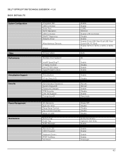
...;: SATA-0 Password: AC Recovery: Auto On Time: Deep Sleep Control: Fan Control Override: Wake on LAN: Service Tag: Asset Tag: SERR Message: Numlock LED: USB Emulation: Keyboard Errors: POST HotKeys: Fast Boot: Enable Enable COM1 RAID On Enable USB Controller Disable Enable Enable (Front USB, Rear Dual USB, Rear Quad USB, PCI Slot) Enable (SATA-0, SATA-1, SATA-2, SATA3) Auto All Enable Disable Enable Enable Enable Disable Not set Not set Enable Disable Enable Deactivate Not set Power Off Disable Disable Disable Disable Set by the factory Optional User Entry Enable Enable Enable Enable Enable...
...;: SATA-0 Password: AC Recovery: Auto On Time: Deep Sleep Control: Fan Control Override: Wake on LAN: Service Tag: Asset Tag: SERR Message: Numlock LED: USB Emulation: Keyboard Errors: POST HotKeys: Fast Boot: Enable Enable COM1 RAID On Enable USB Controller Disable Enable Enable (Front USB, Rear Dual USB, Rear Quad USB, PCI Slot) Enable (SATA-0, SATA-1, SATA-2, SATA3) Auto All Enable Disable Enable Enable Enable Disable Not set Not set Enable Disable Enable Deactivate Not set Power Off Disable Disable Disable Disable Set by the factory Optional User Entry Enable Enable Enable Enable Enable...


