User Manual
Page 8
...8482;, ATI Radeon™, and ATI FirePro™ are trademarks of Advanced Micro Devices, Inc. The Bluetooth® word mark is a registered trademark and owned by Dell Inc. Other trademarks and trade names may be used in the United States and/or other countries....Centrino®, and Celeron® are registered trademarks or trademarks of Intel Corporation in this text: Dell™, the DELL logo, Dell Precision™, Precision ON™, ExpressCharge™, Latitude™, Latitude ON™, OptiPlex™, Vostro™, and Wi-Fi Catcher™ are either trademarks or ...
...8482;, ATI Radeon™, and ATI FirePro™ are trademarks of Advanced Micro Devices, Inc. The Bluetooth® word mark is a registered trademark and owned by Dell Inc. Other trademarks and trade names may be used in the United States and/or other countries....Centrino®, and Celeron® are registered trademarks or trademarks of Intel Corporation in this text: Dell™, the DELL logo, Dell Precision™, Precision ON™, ExpressCharge™, Latitude™, Latitude ON™, OptiPlex™, Vostro™, and Wi-Fi Catcher™ are either trademarks or ...
Owner's Manual
Page 3
... (SIM) Card 13 Installing the Subscriber Identity Module (SIM) Card 13 Removing the Base Cover...13 Installing the Base Cover...14 Removing the Bluetooth Module...14 Installing the Bluetooth Module...15 Removing the Hard Drive...15 Installing the Hard Drive...17 Removing the Memory...17 Installing the Memory...18 Removing The Palmrest...
... (SIM) Card 13 Installing the Subscriber Identity Module (SIM) Card 13 Removing the Base Cover...13 Installing the Base Cover...14 Removing the Bluetooth Module...14 Installing the Bluetooth Module...15 Removing the Hard Drive...15 Installing the Hard Drive...17 Removing the Memory...17 Installing the Memory...18 Removing The Palmrest...
Owner's Manual
Page 14
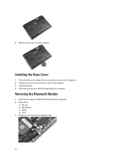
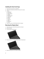
Installing the Base Cover 1. Place the base cover to the computer. 3. Remove the: a) SD card b) ExpressCard c) battery d) cover 3. Install the battery. 4. Removing the Bluetooth Module 1. 4. Slide the base cover out of the computer. Follow the procedures in After Working Inside Your Computer. Disconnect and unroute the bluetooth cable. 14 Tighten the screw to secure the base cover to align with the screw hole correctly on the computer. 2. Follow the procedures in Before Working Inside Your Computer. 2.
Installing the Base Cover 1. Place the base cover to the computer. 3. Remove the: a) SD card b) ExpressCard c) battery d) cover 3. Install the battery. 4. Removing the Bluetooth Module 1. 4. Slide the base cover out of the computer. Follow the procedures in After Working Inside Your Computer. Disconnect and unroute the bluetooth cable. 14 Tighten the screw to secure the base cover to align with the screw hole correctly on the computer. 2. Follow the procedures in Before Working Inside Your Computer. 2.

Owner's Manual
Page 15
... the screw that secure the hard drive to the computer. 3. Tighten the screw to secure the bluetooth module to the computer. 15 Installing the Bluetooth Module 1. Remove the: a) battery b) base cover 3. Remove the bluetooth module. Remove the screws that secures the bluetooth module to its connector. 2. Install the: a) base cover b) battery c) ExpressCard d) SD card...
... the screw that secure the hard drive to the computer. 3. Tighten the screw to secure the bluetooth module to the computer. 15 Installing the Bluetooth Module 1. Remove the: a) battery b) base cover 3. Remove the bluetooth module. Remove the screws that secures the bluetooth module to its connector. 2. Install the: a) base cover b) battery c) ExpressCard d) SD card...

Owner's Manual
Page 28
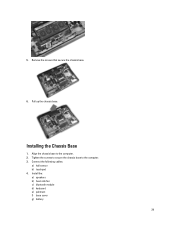
... connect the speaker cables. 2. Installing the Speakers 1. Tighten the screws to secure both the speakers 3. Remove the: a) SD card b) ExpressCard c) battery d) base cover e) palmrest f) keyboard g) bluetooth module h) heat-sink fan i) speakers 3. Removing the Chassis Base 1.
... connect the speaker cables. 2. Installing the Speakers 1. Tighten the screws to secure both the speakers 3. Remove the: a) SD card b) ExpressCard c) battery d) base cover e) palmrest f) keyboard g) bluetooth module h) heat-sink fan i) speakers 3. Removing the Chassis Base 1.
Owner's Manual
Page 29
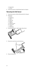
Tighten the screws to secure the chassis base to the computer. 2. Install the: a) speakers b) heat-sink fan c) bluetooth module d) keyboard e) palmrest f) base cover g) battery 29 Align the chassis base to the computer. 3. Pull up the chassis base. Installing the Chassis Base 1. Connect the following cables: a) hall sensor b) touchpad 4. 5. Remove the screws that secure the chassis base. 6.
Tighten the screws to secure the chassis base to the computer. 2. Install the: a) speakers b) heat-sink fan c) bluetooth module d) keyboard e) palmrest f) base cover g) battery 29 Align the chassis base to the computer. 3. Pull up the chassis base. Installing the Chassis Base 1. Connect the following cables: a) hall sensor b) touchpad 4. 5. Remove the screws that secure the chassis base. 6.
Owner's Manual
Page 30
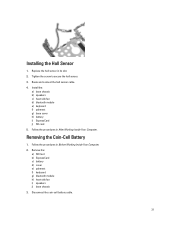
Remove the hall sensor. 30 Removing the Hall Sensor 1. Follow the procedures in After Working Inside Your Computer. Remove the: a) SD card b) ExpressCard c) battery d) base cover e) palmrest f) keyboard g) bluetooth module h) heat-sink fan i) speakers j) base chassis 3. Unthread the hall sensor cable from the routing channel. 4. Follow the procedures in Before Working Inside Your Computer. 2. Remove the screw that secures the hall sensor. 5. h) ExpressCard i) SD card 5.
Remove the hall sensor. 30 Removing the Hall Sensor 1. Follow the procedures in After Working Inside Your Computer. Remove the: a) SD card b) ExpressCard c) battery d) base cover e) palmrest f) keyboard g) bluetooth module h) heat-sink fan i) speakers j) base chassis 3. Unthread the hall sensor cable from the routing channel. 4. Follow the procedures in Before Working Inside Your Computer. 2. Remove the screw that secures the hall sensor. 5. h) ExpressCard i) SD card 5.
Owner's Manual
Page 31
... h) heat-sink fan i) speakers j) base chassis 3. Route and connect the hall sensor cable. 4. Install the: a) base chassis b) speakers c) heat-sink fan d) bluetooth module e) keyboard f) palmrest g) base cover h) battery i) ExpressCard j) SD card 5. Tighten the screw to secure the hall sensor. 3. Removing the Coin-Cell Battery 1. Disconnect the coin-...
... h) heat-sink fan i) speakers j) base chassis 3. Route and connect the hall sensor cable. 4. Install the: a) base chassis b) speakers c) heat-sink fan d) bluetooth module e) keyboard f) palmrest g) base cover h) battery i) ExpressCard j) SD card 5. Tighten the screw to secure the hall sensor. 3. Removing the Coin-Cell Battery 1. Disconnect the coin-...
Owner's Manual
Page 32
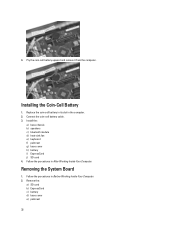
... b) ExpressCard c) battery d) base cover e) palmrest 32 Replace the coin-cell battery in its slot in Before Working Inside Your Computer. 2. Install the: a) base chassis b) speakers c) bluetooth module d) heat-sink fan e) keyboard f) palmrest g) base cover h) battery i) ExpressCard j) SD card 4. 4. Removing the System Board 1. Follow the procedures in After Working Inside Your Computer...
... b) ExpressCard c) battery d) base cover e) palmrest 32 Replace the coin-cell battery in its slot in Before Working Inside Your Computer. 2. Install the: a) base chassis b) speakers c) bluetooth module d) heat-sink fan e) keyboard f) palmrest g) base cover h) battery i) ExpressCard j) SD card 4. 4. Removing the System Board 1. Follow the procedures in After Working Inside Your Computer...
Owner's Manual
Page 33
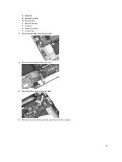
Disconnect the power-connector cable. 6. Remove the screws that secure the system board to the computer. 33 Disconnect the ExpressCard cage cable. 5. Disconnect the WiFi-switch board cable. 4. f) keyboard g) bluetooth module h) heat-sink fan i) heat sink module j) speakers k) display assembly l) chassis base 3.
Disconnect the power-connector cable. 6. Remove the screws that secure the system board to the computer. 33 Disconnect the ExpressCard cage cable. 5. Disconnect the WiFi-switch board cable. 4. f) keyboard g) bluetooth module h) heat-sink fan i) heat sink module j) speakers k) display assembly l) chassis base 3.
Owner's Manual
Page 34
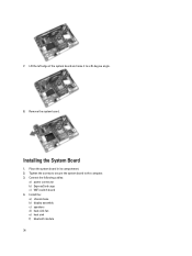
Connect the following cables: a) power connector b) ExpressCard cage c) WiFi-switch board 4. Tighten the screws to secure the system board to a 45-degree angle. 8. 7. Remove the system board. Installing the System Board 1. Lift the left edge of the system board and raise it to the computer. 3. Install the: a) chassis base b) display assembly c) speakers d) heat-sink fan e) heat sink f) bluetooth module 34 Place the system board in its compartment. 2.
Connect the following cables: a) power connector b) ExpressCard cage c) WiFi-switch board 4. Tighten the screws to secure the system board to a 45-degree angle. 8. 7. Remove the system board. Installing the System Board 1. Lift the left edge of the system board and raise it to the computer. 3. Install the: a) chassis base b) display assembly c) speakers d) heat-sink fan e) heat sink f) bluetooth module 34 Place the system board in its compartment. 2.
Owner's Manual
Page 35
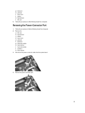
Follow the procedures in After Working Inside Your Computer. Remove the: a) SD card b) ExpressCard c) battery d) base cover e) palmrest f) keyboard g) bluetooth module h) heat-sink fan i) heat-sink module j) speakers k) base chassis 3. Remove the power connector port. 35 g) keyboard h) palmrest i) base cover j) battery k) ExpressCard l) SD card 5. Follow the procedures in Before Working Inside Your Computer. 2. Disconnect the power-connector cable from the system board. 4. Removing the Power-Connector Port 1.
Follow the procedures in After Working Inside Your Computer. Remove the: a) SD card b) ExpressCard c) battery d) base cover e) palmrest f) keyboard g) bluetooth module h) heat-sink fan i) heat-sink module j) speakers k) base chassis 3. Remove the power connector port. 35 g) keyboard h) palmrest i) base cover j) battery k) ExpressCard l) SD card 5. Follow the procedures in Before Working Inside Your Computer. 2. Disconnect the power-connector cable from the system board. 4. Removing the Power-Connector Port 1.

Owner's Manual
Page 36
... f) keyboard g) palmrest h) base cover i) battery j) ExpressCard k) SD card 4. Remove the: a) SD card b) ExpressCard c) battery d) base cover e) palmrest f) keyboard g) bluetooth module h) heat sink i) speakers j) base chassis 3. Removing the ExpressCard Cage 1. Follow the procedures in its slot. 2. Disconnect the ExpressCard reader cable. 4. Insert the power-connector ...
... f) keyboard g) palmrest h) base cover i) battery j) ExpressCard k) SD card 4. Remove the: a) SD card b) ExpressCard c) battery d) base cover e) palmrest f) keyboard g) bluetooth module h) heat sink i) speakers j) base chassis 3. Removing the ExpressCard Cage 1. Follow the procedures in its slot. 2. Disconnect the ExpressCard reader cable. 4. Insert the power-connector ...

Owner's Manual
Page 37
Insert the ExpressCard cage into its compartment. 2. Follow the procedures in Before Working Inside Your Computer. 2. Install the: a) base chassis b) speakers c) heatsink d) bluetooth module e) keyboard f) palmrest g) base cover h) battery i) ExpressCard j) SD card 5. Removing the WiFi-Switch Board 1. Installing the ExpressCard Cage 1. Connect the ExpressCard reader cable. 4. Tighten the ...
Insert the ExpressCard cage into its compartment. 2. Follow the procedures in Before Working Inside Your Computer. 2. Install the: a) base chassis b) speakers c) heatsink d) bluetooth module e) keyboard f) palmrest g) base cover h) battery i) ExpressCard j) SD card 5. Removing the WiFi-Switch Board 1. Installing the ExpressCard Cage 1. Connect the ExpressCard reader cable. 4. Tighten the ...
Owner's Manual
Page 38
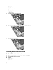
Remove the screw that secures the WiFi-switch board to the computer. 3. Tighten the screw to secures the WiFi-switch board to the computer. 5. Install the: a) base chassis b) speakers 38 Remove the WiFi-switch board. Connect the WiFi-switch board cable. 4. Installing the WiFi-Switch Board 1. Disconnect the WiFi-switch board cable. 4. Place the WiFi-switch board in its compartment. 2. e) palmrest f) keyboard g) bluetooth module h) heat-sink fan i) speakers j) base chassis 3.
Remove the screw that secures the WiFi-switch board to the computer. 3. Tighten the screw to secures the WiFi-switch board to the computer. 5. Install the: a) base chassis b) speakers 38 Remove the WiFi-switch board. Connect the WiFi-switch board cable. 4. Installing the WiFi-Switch Board 1. Disconnect the WiFi-switch board cable. 4. Place the WiFi-switch board in its compartment. 2. e) palmrest f) keyboard g) bluetooth module h) heat-sink fan i) speakers j) base chassis 3.
Owner's Manual
Page 39
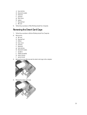
Remove the: a) SD card b) ExpressCard c) battery d) base cover e) palmrest f) keyboard g) heat-sink fan h) bluetooth module i) speakers j) display assembly k) lower chassis l) system board 3. Removing the Smart Card Cage 1. c) heat-sink fan d) bluetooth module e) keyboard f) palmrest g) base cover h) battery i) ExpressCard j) SD card 5. Remove the smart card cage. 39 Follow the procedures in After Working Inside Your Computer. Follow the procedures in Before Working Inside Your Computer. 2. Remove the screw that secures the smart card cage to the computer. 4.
Remove the: a) SD card b) ExpressCard c) battery d) base cover e) palmrest f) keyboard g) heat-sink fan h) bluetooth module i) speakers j) display assembly k) lower chassis l) system board 3. Removing the Smart Card Cage 1. c) heat-sink fan d) bluetooth module e) keyboard f) palmrest g) base cover h) battery i) ExpressCard j) SD card 5. Remove the smart card cage. 39 Follow the procedures in After Working Inside Your Computer. Follow the procedures in Before Working Inside Your Computer. 2. Remove the screw that secures the smart card cage to the computer. 4.
Owner's Manual
Page 40
... from the display assembly. 40 Place the smart card cage in After Working Inside Your Computer. Install the: a) system board b) base chassis c) display assembly d) speakers e) bluetooth module f) heat-sink fan g) keyboard h) palmrest i) base cover j) battery k) ExpressCard l) SD card 4. Tighten the screw that secures the smart card cage to the sides and...
... from the display assembly. 40 Place the smart card cage in After Working Inside Your Computer. Install the: a) system board b) base chassis c) display assembly d) speakers e) bluetooth module f) heat-sink fan g) keyboard h) palmrest i) base cover j) battery k) ExpressCard l) SD card 4. Tighten the screw that secures the smart card cage to the sides and...
Owner's Manual
Page 59
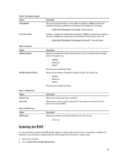
...Setting. Allows you to create a system asset tag if an asset tag is available. The options are: • WWAN • Bluetooth • WLAN All options are enabled by default. Description Displays the system event log and allows you to determine which wireless device can... by Intel Virtualization technology. • Enable Intel Virtualization Technology - For notebooks, ensure that your computer. The options are: • WWAN • Bluetooth • WLAN All options are enabled by the wireless switch. System Logs Option BIOS events Description Allows you to support...
...Setting. Allows you to create a system asset tag if an asset tag is available. The options are: • WWAN • Bluetooth • WLAN All options are enabled by default. Description Displays the system event log and allows you to determine which wireless device can... by Intel Virtualization technology. • Enable Intel Virtualization Technology - For notebooks, ensure that your computer. The options are: • WWAN • Bluetooth • WLAN All options are enabled by the wireless switch. System Logs Option BIOS events Description Allows you to support...


