User Manual
Page 1
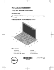
microphone 2. power button 6. camera status light (optional) 4. Dell Latitude E6230/E6330 Setup and Features Information About Warnings WARNING: A WARNING indicates a potential for property damage, personal injury, or death. camera (optional) 3. HDMI connector Regulatory Model: : P14T, P19S Regulatory Type: : P14T001, P19S001 2012- 02 display 5. Front View 1. Latitude E6230 Front and Back View Figure 1.
microphone 2. power button 6. camera status light (optional) 4. Dell Latitude E6230/E6330 Setup and Features Information About Warnings WARNING: A WARNING indicates a potential for property damage, personal injury, or death. camera (optional) 3. HDMI connector Regulatory Model: : P14T, P19S Regulatory Type: : P14T001, P19S001 2012- 02 display 5. Front View 1. Latitude E6230 Front and Back View Figure 1.
User Manual
Page 3
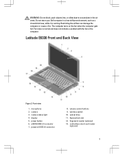
.... Front view 1. ExpressCard slot 12. microphone 2. power button 6. contactless smart card reader (optional) 3 Do not store your Dell computer in the air vents. Restricting the airflow can damage the computer or cause a fire. camera status light 4. display 5. eSATA/USB 2.0 connector 7. The computer turns on the fan when the computer gets hot. Fan... to accumulate in a low-airflow environment, such as a closed briefcase, while it is normal and does not indicate a problem with the fan or the computer. Latitude E6330 Front and Back View Figure 3.
.... Front view 1. ExpressCard slot 12. microphone 2. power button 6. contactless smart card reader (optional) 3 Do not store your Dell computer in the air vents. Restricting the airflow can damage the computer or cause a fire. camera status light 4. display 5. eSATA/USB 2.0 connector 7. The computer turns on the fan when the computer gets hot. Fan... to accumulate in a low-airflow environment, such as a closed briefcase, while it is normal and does not indicate a problem with the fan or the computer. Latitude E6330 Front and Back View Figure 3.
Owner's Manual
Page 4
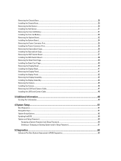
......41 Installing the Display Panel...42 Removing the Display Assembly...42 Installing the Display Assembly...44 Removing the Camera...45 Installing the Camera...46 Removing the LVDS and Camera Cable...47 Installing the LVDS and Camera Cable...48 3 Additional Information...49 Docking Port Information...49 4 System Setup...51 Boot Sequence...51 Navigation Keys...51...
......41 Installing the Display Panel...42 Removing the Display Assembly...42 Installing the Display Assembly...44 Removing the Camera...45 Installing the Camera...46 Removing the LVDS and Camera Cable...47 Installing the LVDS and Camera Cable...48 3 Additional Information...49 Docking Port Information...49 4 System Setup...51 Boot Sequence...51 Navigation Keys...51...
Owner's Manual
Page 45
.... 2. Tighten the screws to secure the LVDS bracket to the computer. 5. Connect the antenna cables to the computer. 8. Lift up the right edge of the camera. 45 Place the LVDS bracket in its slot. 7. Route the antenna cables through the routing channel. 4. 3. Route and connect the antenna cables that secures the...
.... 2. Tighten the screws to secure the LVDS bracket to the computer. 5. Connect the antenna cables to the computer. 8. Lift up the right edge of the camera. 45 Place the LVDS bracket in its slot. 7. Route the antenna cables through the routing channel. 4. 3. Route and connect the antenna cables that secures the...
Owner's Manual
Page 46
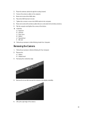
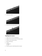
Affix the conductive tape. 5. Install the: a) display bezel b) battery 6. Follow the procedures in its slot on the display panel. 2. Disconnect the camera cable and remove the camera. Install the camera in After Working Inside Your Computer. 46 Tighten the screw to secure the camera to the camera. 4. Installing the Camera 1. Flip the camera outwards. 7. Connect the camera cable to the display assembly. 3. 6.
Affix the conductive tape. 5. Install the: a) display bezel b) battery 6. Follow the procedures in its slot on the display panel. 2. Disconnect the camera cable and remove the camera. Install the camera in After Working Inside Your Computer. 46 Tighten the screw to secure the camera to the camera. 4. Installing the Camera 1. Flip the camera outwards. 7. Connect the camera cable to the display assembly. 3. 6.
Owner's Manual
Page 47
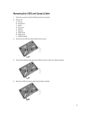
Remove the LVDS and camera cable from the camera. 4. Follow the procedures in Before Working Inside Your Computer. 2. Remove the: a) SD card b) ExpressCard c) battery d) base cover e) palmrest f) keyboard g) display bezel h) display panel i) display assembly 3. Disconnect the LVDS and camera cable from the display assembly. 47 Peel back the adhesives that secures the LVDS and camera cable to the display assembly. 5. Removing the LVDS and Camera Cable 1.
Remove the LVDS and camera cable from the camera. 4. Follow the procedures in Before Working Inside Your Computer. 2. Remove the: a) SD card b) ExpressCard c) battery d) base cover e) palmrest f) keyboard g) display bezel h) display panel i) display assembly 3. Disconnect the LVDS and camera cable from the display assembly. 47 Peel back the adhesives that secures the LVDS and camera cable to the display assembly. 5. Removing the LVDS and Camera Cable 1.
Owner's Manual
Page 48
Install the: a) display assembly b) display panel c) display bezel d) keyboard e) palmrest f) base cover g) battery h) ExpressCard i) SD card 4. Affix the LVDS and camera cable to the display assembly. 2. Connect the LVDS and camera cable. 3. Follow the procedures in After Working Inside Your Computer. 48 Installing the LVDS and Camera Cable 1.
Install the: a) display assembly b) display panel c) display bezel d) keyboard e) palmrest f) base cover g) battery h) ExpressCard i) SD card 4. Affix the LVDS and camera cable to the display assembly. 2. Connect the LVDS and camera cable. 3. Follow the procedures in After Working Inside Your Computer. 48 Installing the LVDS and Camera Cable 1.
Owner's Manual
Page 54
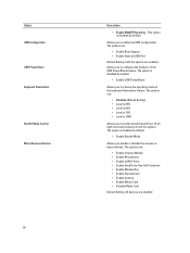
... Internal Modem • Enable Microphone • Enable eSATA Ports • Enable Hard Drive Free Fall Protection • Enable Module Bay • Enable ExpressCard • Enable Camera • Enable Media Card • Disable Media Card Default Setting: All devices are : • Disabled (Default Setting) • Level is 25% • Level is 50...
... Internal Modem • Enable Microphone • Enable eSATA Ports • Enable Hard Drive Free Fall Protection • Enable Module Bay • Enable ExpressCard • Enable Camera • Enable Media Card • Disable Media Card Default Setting: All devices are : • Disabled (Default Setting) • Level is 25% • Level is 50...


