User Manual
Page 1
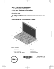
camera (optional) 3. power button 6. HDMI connector Regulatory Model: : P14T, P19S Regulatory Type: : P14T001, P19S001 2012- 02 display 5. Front View 1. Latitude E6230 Front and Back View Figure 1. camera status light (optional) 4. microphone 2. Dell Latitude E6230/E6330 Setup and Features Information About Warnings WARNING: A WARNING indicates a potential for property damage, personal injury, or death.
camera (optional) 3. power button 6. HDMI connector Regulatory Model: : P14T, P19S Regulatory Type: : P14T001, P19S001 2012- 02 display 5. Front View 1. Latitude E6230 Front and Back View Figure 1. camera status light (optional) 4. microphone 2. Dell Latitude E6230/E6330 Setup and Features Information About Warnings WARNING: A WARNING indicates a potential for property damage, personal injury, or death.
User Manual
Page 2
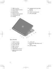
contactless smart-card reader (optional) 15. keyboard 16. network connector 2. security cable slot 4. 7. device status lights Figure 2. VGA connector 6. audio/microphone combo connector 8. smart card reader 2 ExpressCard slot 11. Back View 1. eSATA/USB 2.0 connector 7. powered USB 3.0 connector 9. fingerprint reader (optional) 12. volume control buttons (3) 17. power connector 5. touchpad 14. cooling vents 9. USB 3.0 connector 8. Secure Digital (SD) memory-card reader 10. wireless switch 10. touchpad buttons (2) 13. device status lights 3.
contactless smart-card reader (optional) 15. keyboard 16. network connector 2. security cable slot 4. 7. device status lights Figure 2. VGA connector 6. audio/microphone combo connector 8. smart card reader 2 ExpressCard slot 11. Back View 1. eSATA/USB 2.0 connector 7. powered USB 3.0 connector 9. fingerprint reader (optional) 12. volume control buttons (3) 17. power connector 5. touchpad 14. cooling vents 9. USB 3.0 connector 8. Secure Digital (SD) memory-card reader 10. wireless switch 10. touchpad buttons (2) 13. device status lights 3.
User Manual
Page 4
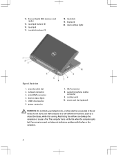
... normal and does not indicate a problem with the fan or the computer. 4 Do not store your Dell computer in the air vents. device status lights Figure 4. The computer turns on the fan when the computer gets hot. trackstick 19. security cable slot 2. keyboard 20. Back view 1. power connector 7. audio/microphone combo connector 9. Secure Digital (SD) memory-card reader 15. touchpad buttons (2) 16. network connector 3. mini HDMI connector 4. 14. touchpad 17. Restricting the airflow...
... normal and does not indicate a problem with the fan or the computer. 4 Do not store your Dell computer in the air vents. device status lights Figure 4. The computer turns on the fan when the computer gets hot. trackstick 19. security cable slot 2. keyboard 20. Back view 1. power connector 7. audio/microphone combo connector 9. Secure Digital (SD) memory-card reader 15. touchpad buttons (2) 16. network connector 3. mini HDMI connector 4. 14. touchpad 17. Restricting the airflow...
Owner's Manual
Page 3
... Removing The Battery...12 Installing the Battery...13 Removing the Subscriber Identity Module (SIM) Card 13 Installing the Subscriber Identity Module (SIM) Card 13 Removing the Base Cover...13 Installing the Base Cover...14 Removing the Bluetooth Module...14 Installing the Bluetooth Module...15 Removing the Hard Drive...15 Installing the Hard Drive...17 Removing the Memory...17 Installing the Memory...18 Removing The Palmrest...18 Installing the Palmrest...20 Removing the Keyboard...21 Installing the Keyboard...22 Removing the Wireless Local Access Network (WLAN 23 Installing the Wireless...
... Removing The Battery...12 Installing the Battery...13 Removing the Subscriber Identity Module (SIM) Card 13 Installing the Subscriber Identity Module (SIM) Card 13 Removing the Base Cover...13 Installing the Base Cover...14 Removing the Bluetooth Module...14 Installing the Bluetooth Module...15 Removing the Hard Drive...15 Installing the Hard Drive...17 Removing the Memory...17 Installing the Memory...18 Removing The Palmrest...18 Installing the Palmrest...20 Removing the Keyboard...21 Installing the Keyboard...22 Removing the Wireless Local Access Network (WLAN 23 Installing the Wireless...
Owner's Manual
Page 7
... safety information that your work surface is not covered by your product documentation, or as directed by performing the removal procedure in your warranty. Hold a card by its metal mounting bracket. Hold a component such as the optional Media Base or Battery Slice, undock it. As you connect a cable, ensure that the following safety guidelines to a docking device (docked) such as...
... safety information that your work surface is not covered by your product documentation, or as directed by performing the removal procedure in your warranty. Hold a card by its metal mounting bracket. Hold a component such as the optional Media Base or Battery Slice, undock it. As you connect a cable, ensure that the following safety guidelines to a docking device (docked) such as...
Owner's Manual
Page 8
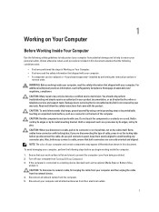
... an ExpressCard. 2. CAUTION: Before touching anything inside your computer and attached devices did not automatically turn the computer upside-down the operating system: - In Windows XP: Click Start → Turn Off Computer → Turn Off . Connect any external devices, such as a port replicator, battery slice, or media base, and replace any external devices, cards, and cables before you work surface. Press the power button to the computer, use batteries designed for about 4 seconds to...
... an ExpressCard. 2. CAUTION: Before touching anything inside your computer and attached devices did not automatically turn the computer upside-down the operating system: - In Windows XP: Click Start → Turn Off Computer → Turn Off . Connect any external devices, such as a port replicator, battery slice, or media base, and replace any external devices, cards, and cables before you work surface. Press the power button to the computer, use batteries designed for about 4 seconds to...

Owner's Manual
Page 15
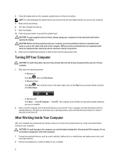
Follow the procedures in Before Working Inside Your Computer. 2. Remove the screws that secures the bluetooth module to the computer. 3. Remove the bluetooth module. Remove the: a) battery b) base cover 3. 4. Removing the Hard Drive 1. Installing the Bluetooth Module 1. Install the: a) base cover b) battery c) ExpressCard d) SD card 4. Connect the bluetooth cable to the computer. 15 Tighten the screw to secure the bluetooth module to the computer. 5. Remove the screw that secure the hard drive to its connector. 2. Follow the procedures in...
Follow the procedures in Before Working Inside Your Computer. 2. Remove the screws that secures the bluetooth module to the computer. 3. Remove the bluetooth module. Remove the: a) battery b) base cover 3. 4. Removing the Hard Drive 1. Installing the Bluetooth Module 1. Install the: a) base cover b) battery c) ExpressCard d) SD card 4. Connect the bluetooth cable to the computer. 15 Tighten the screw to secure the bluetooth module to the computer. 5. Remove the screw that secure the hard drive to its connector. 2. Follow the procedures in...
Owner's Manual
Page 17
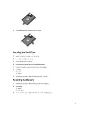
... in its slot. 4. 8. Attach the hard-drive caddy to the computer. 6. Tighten the screws to secure the hard drive to the hard drive. 2. Install the: a) cover b) battery 7. Replace the hard drive in Before Working Inside Your Computer. 2. Pry the retention clips away from the hard drive. Installing the Hard Drive 1. Replace the hard-drive bracket to secure the hard drive. 5. Remove the: a) battery b) base cover 3. Remove the hard-drive caddy from the memory module until it pops-up. 17 Connect the hard-drive connector. 3. Follow...
... in its slot. 4. 8. Attach the hard-drive caddy to the computer. 6. Tighten the screws to secure the hard drive to the hard drive. 2. Install the: a) cover b) battery 7. Replace the hard drive in Before Working Inside Your Computer. 2. Pry the retention clips away from the hard drive. Installing the Hard Drive 1. Replace the hard-drive bracket to secure the hard drive. 5. Remove the: a) battery b) base cover 3. Remove the hard-drive caddy from the memory module until it pops-up. 17 Connect the hard-drive connector. 3. Follow...
Owner's Manual
Page 51
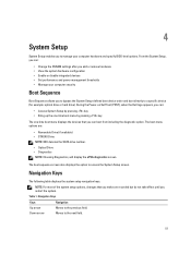
... the System Setup‐defined boot device order and boot directly to a specific device (for example: optical drive or hard drive). During the Power-on Self Test (POST), when the Dell logo appears, you can : • Change the NVRAM settings after you add or remove hardware • View the system hardware configuration • Enable or disable integrated devices • Set performance and power management thresholds • Manage your computer hardware and specify BIOS‐level options. Navigation Keys Keys Navigation...
... the System Setup‐defined boot device order and boot directly to a specific device (for example: optical drive or hard drive). During the Power-on Self Test (POST), when the Dell logo appears, you can : • Change the NVRAM settings after you add or remove hardware • View the system hardware configuration • Enable or disable integrated devices • Set performance and power management thresholds • Manage your computer hardware and specify BIOS‐level options. Navigation Keys Keys Navigation...

Owner's Manual
Page 52
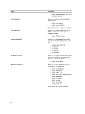
...; Memory Information • Processor Information • Device Information Battery Information Boot Sequence Displays the charge status of your computer and its installed devices, the items listed in the field. All the below options are : 52 The options are: • Legacy (Default Setting) • UEFI Date/Time Allows you to configure the integrated network controller. The options are selected. • Diskette Drive • Internal HDD • USB Storage Device • CD/DVD/CD-RW Drive...
...; Memory Information • Processor Information • Device Information Battery Information Boot Sequence Displays the charge status of your computer and its installed devices, the items listed in the field. All the below options are : 52 The options are: • Legacy (Default Setting) • UEFI Date/Time Allows you to configure the integrated network controller. The options are selected. • Diskette Drive • Internal HDD • USB Storage Device • CD/DVD/CD-RW Drive...
Owner's Manual
Page 54
... mode that will turn off all light and sound emissions from the system. The options are: • Enable Boot Support • Enable External USB Port Default Setting: both the options are enabled The options are: • Enable Internal Modem • Enable Microphone • Enable eSATA Ports • Enable Hard Drive Free Fall Protection • Enable Module Bay • Enable ExpressCard • Enable Camera • Enable Media Card • Disable Media Card Default Setting: All devices are enabled. Allows you to define the USB configuration. Option USB Configuration...
... mode that will turn off all light and sound emissions from the system. The options are: • Enable Boot Support • Enable External USB Port Default Setting: both the options are enabled The options are: • Enable Internal Modem • Enable Microphone • Enable eSATA Ports • Enable Hard Drive Free Fall Protection • Enable Module Bay • Enable ExpressCard • Enable Camera • Enable Media Card • Disable Media Card Default Setting: All devices are enabled. Allows you to define the USB configuration. Option USB Configuration...
Owner's Manual
Page 55
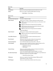
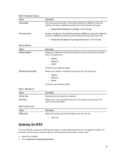
... password and the hard drive password. NOTE: Successful password changes take effect immediately. Table 4. Table 5. Security Option Intel TXT (LT-SX) Configuration Admin Password System Password Internal HDD-0 Password Strong Password Password Configuration Password Bypass Password Change Non-Admin Setup Changes TPM Security CPU XD Support Description This option is disabled. Allows you to determine whether changes to set . NOTE: Successful password changes take effect immediately. Default Setting: Enable Strong Password is disabled. • Allows Wireless Switch Changes...
... password and the hard drive password. NOTE: Successful password changes take effect immediately. Table 4. Table 5. Security Option Intel TXT (LT-SX) Configuration Admin Password System Password Internal HDD-0 Password Strong Password Password Configuration Password Bypass Password Change Non-Admin Setup Changes TPM Security CPU XD Support Description This option is disabled. Allows you to determine whether changes to set . NOTE: Successful password changes take effect immediately. Default Setting: Enable Strong Password is disabled. • Allows Wireless Switch Changes...
Owner's Manual
Page 58
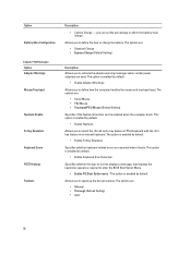
.... The options are used. Option Battery Slice Configuration Table 8. The options are: • Standard Charge • Express Charge (Default Setting) Description Allows you to enter the BIOS Boot Option Menu. • Enable F12 Boot Option menu - The options are reported when it boots. you to which the battery must charge . This option is enabled by default. • Enable Adapter Warnings Allows you can be enabled when the computer boots. The option is enabled by default. • Enable Fn Key Emulation Specifies whether keyboard related errors are : • Serial Mouse...
.... The options are used. Option Battery Slice Configuration Table 8. The options are: • Standard Charge • Express Charge (Default Setting) Description Allows you to enter the BIOS Boot Option Menu. • Enable F12 Boot Option menu - The options are reported when it boots. you to which the battery must charge . This option is enabled by default. • Enable Adapter Warnings Allows you can be enabled when the computer boots. The option is enabled by default. • Enable Fn Key Emulation Specifies whether keyboard related errors are : • Serial Mouse...
Owner's Manual
Page 59
... default. Allows you to clear the log. • Clear Log Updating the BIOS It is fully charged and connected to update your computer. Go to enable or disable the wireless devices. Default Setting. Default Setting. Virtualization Support Option Virtualization VT for Direct I /O Description This option specifies whether a Virtual Machine Monitor (VMM) can be controlled by the wireless switch. Maintenance Option Service Tag Asset Tag Table 12. For notebooks, ensure that your computer battery is recommended to a power outlet 1. Description Displays...
... default. Allows you to clear the log. • Clear Log Updating the BIOS It is fully charged and connected to update your computer. Go to enable or disable the wireless devices. Default Setting. Default Setting. Virtualization Support Option Virtualization VT for Direct I /O Description This option specifies whether a Virtual Machine Monitor (VMM) can be controlled by the wireless switch. Maintenance Option Service Tag Asset Tag Table 12. For notebooks, ensure that your computer battery is recommended to a power outlet 1. Description Displays...
Owner's Manual
Page 60
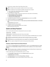
... the Password Status is Unlocked. 3. In the System BIOS or System Setup screen, select System Security and press . Click Run to your computer. To enter a system setup, press immediately after a power-on your system. On the application and drivers screen, under the Operating System drop-down list, select BIOS. 6. Follow the instructions on to install the updated BIOS settings on or reboot. 1. Password Type Description System password Password that you must enter to the BIOS settings...
... the Password Status is Unlocked. 3. In the System BIOS or System Setup screen, select System Security and press . Click Run to your computer. To enter a system setup, press immediately after a power-on your system. On the application and drivers screen, under the Operating System drop-down list, select BIOS. 6. Follow the instructions on to install the updated BIOS settings on or reboot. 1. Password Type Description System password Password that you must enter to the BIOS settings...

Owner's Manual
Page 63
... launched by the BIOS internally. Select the device from the left pane and click Run Tests. 6. The embedded system diagnostics provides a set of problems encountered during testing CAUTION: Use the system diagnostics to help you solve the problem. On the boot menu screen, select the Diagnostics option. The ePSA is displayed, listing all the detected devices. 4. Power-on all devices detected in an interactive mode • Repeat...
... launched by the BIOS internally. Select the device from the left pane and click Run Tests. 6. The embedded system diagnostics provides a set of problems encountered during testing CAUTION: Use the system diagnostics to help you solve the problem. On the boot menu screen, select the Diagnostics option. The ePSA is displayed, listing all the detected devices. 4. Power-on all devices detected in an interactive mode • Repeat...
Owner's Manual
Page 65
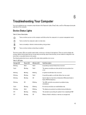
... operation of the keyboard. Turns on hard drive initialization OR System failed in a power management mode. Blinking Solid Blinking The display encountered a problem during initialization. The following table lists how to read the LED codes when possible errors occur. Blinking Off Blinking The USB controller encountered a problem during initialization. Blinking Blinking Solid A possible graphics card/video failure has occurred. The device status LEDs are used to display the storage, battery and wireless devices connectivity and activity. LED Lights Storage LED...
... operation of the keyboard. Turns on hard drive initialization OR System failed in a power management mode. Blinking Solid Blinking The display encountered a problem during initialization. The following table lists how to read the LED codes when possible errors occur. Blinking Off Blinking The USB controller encountered a problem during initialization. Blinking Blinking Solid A possible graphics card/video failure has occurred. The device status LEDs are used to display the storage, battery and wireless devices connectivity and activity. LED Lights Storage LED...
Owner's Manual
Page 68
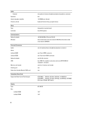
... kbps, and 848 kbps ISO14443B - 106 kbps, 212 kbps, 424 kbps, and 848 kbps ISO15693 HID iClass FIPS201 NXP Desfire HD, WLED 12.5" 13.3" 68 Audio External Speakers Internal speaker amplifier Volume controls Video Type Controller Communications Network adapter Wireless Ports and Connectors Audio Video: Latitude E6230 Latitude E6330 Network adapter USB Memory card reader Docking port Subscriber Identity Module (SIM) card Contactless Smart Card Supported Smart Cards/Technologies Display Type Size Latitude E6230 Latitude E6330 microphone-in -1 memory card reader one one eSATA...
... kbps, and 848 kbps ISO14443B - 106 kbps, 212 kbps, 424 kbps, and 848 kbps ISO15693 HID iClass FIPS201 NXP Desfire HD, WLED 12.5" 13.3" 68 Audio External Speakers Internal speaker amplifier Volume controls Video Type Controller Communications Network adapter Wireless Ports and Connectors Audio Video: Latitude E6230 Latitude E6330 Network adapter USB Memory card reader Docking port Subscriber Identity Module (SIM) card Contactless Smart Card Supported Smart Cards/Technologies Display Type Size Latitude E6230 Latitude E6330 microphone-in -1 memory card reader one one eSATA...
Statement of Volatility
Page 1
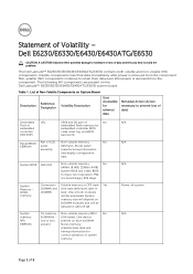
... 1. List of Non-Volatile Components on System Board Reference Description Volatility Description Designator User Accessible for basic boot operation, PSA (on the Dell Latitude™ E6230/E6330/E6430/E6430ATG/E6530 system board. System memory size will depend on each SoDIMM. Non-volatile (NV) components continue to avoid the problem. System BIOS U52,U53 Non-volatile memory, No 64Mbit (8 MB), 32Mbit (4 MB) System BIOS and Video BIOS for external...
... 1. List of Non-Volatile Components on System Board Reference Description Volatility Description Designator User Accessible for basic boot operation, PSA (on the Dell Latitude™ E6230/E6330/E6430/E6430ATG/E6530 system board. System memory size will depend on each SoDIMM. Non-volatile (NV) components continue to avoid the problem. System BIOS U52,U53 Non-volatile memory, No 64Mbit (8 MB), 32Mbit (4 MB) System BIOS and Video BIOS for external...
Statement of Volatility
Page 2
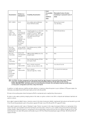
Video UMA Volatile memory in GB. User Non-volatile Yes ROM/RW/ replaceable optical/magnetic media. Linux, Win 2K and Win XP support S3 state. In this state, the dynamic RAM is a low wake-up latency sleeping state. Hard drive User Non-volatile magnetic Yes replaceable media, various sizes in off state. DVD/ DVD+RW/ Diskette Drives Enter S3-S5 state below. S1 state is not maintained. S3 is...
Video UMA Volatile memory in GB. User Non-volatile Yes ROM/RW/ replaceable optical/magnetic media. Linux, Win 2K and Win XP support S3 state. In this state, the dynamic RAM is a low wake-up latency sleeping state. Hard drive User Non-volatile magnetic Yes replaceable media, various sizes in off state. DVD/ DVD+RW/ Diskette Drives Enter S3-S5 state below. S1 state is not maintained. S3 is...


