Setup and Features Information Tech Sheet
Page 1
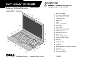
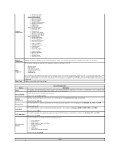
... death. Latitude E5410 - Front View 1 2 3 4 5 6 23 22 21 20 19 18 17 16 15 7 8 9 10 11 12 13 14 1 built-in microphone 2 camera status LED (optional) 3 display latch release switch 4 camera (optional) 5 display latch 6 display 7 volume control buttons 8 power button 9 right speaker 10 modem connector (optional) 11 network connector 12 USB 2.0 connectors (2) 13 optical drive 14 optical drive eject button 15 fingerprint reader (optional) 16 keyboard 17 touchpad buttons 18 wireless switch 19 touchpad 20 trackstick and trackstick buttons (optional) 21 left...
... death. Latitude E5410 - Front View 1 2 3 4 5 6 23 22 21 20 19 18 17 16 15 7 8 9 10 11 12 13 14 1 built-in microphone 2 camera status LED (optional) 3 display latch release switch 4 camera (optional) 5 display latch 6 display 7 volume control buttons 8 power button 9 right speaker 10 modem connector (optional) 11 network connector 12 USB 2.0 connectors (2) 13 optical drive 14 optical drive eject button 15 fingerprint reader (optional) 16 keyboard 17 touchpad buttons 18 wireless switch 19 touchpad 20 trackstick and trackstick buttons (optional) 21 left...
Setup and Features Information Tech Sheet
Page 3
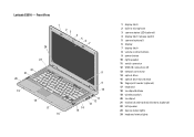
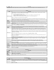
Latitude E5510 - Front View 1 23 4 5 6 7 24 23 22 21 20 19 18 17 16 8 9 10 14 15 11 12 13 1 display latch 2 built-in microphone 3 camera status LED (optional) 4 display latch release switch 5 camera (optional) 6 display 7 display latch 8 volume control buttons 9 power button 10 right speaker 11 serial connector 12 USB 2.0 connectors (2) 13 network connector 14 optical drive 15 optical drive eject button 16 fingerprint reader (optional) 17 keyboard 18 touchpad buttons 19 wireless switch 20 touchpad 21 trackstick and trackstick buttons (optional) 22 left...
Latitude E5510 - Front View 1 23 4 5 6 7 24 23 22 21 20 19 18 17 16 8 9 10 14 15 11 12 13 1 display latch 2 built-in microphone 3 camera status LED (optional) 4 display latch release switch 5 camera (optional) 6 display 7 display latch 8 volume control buttons 9 power button 10 right speaker 11 serial connector 12 USB 2.0 connectors (2) 13 network connector 14 optical drive 15 optical drive eject button 16 fingerprint reader (optional) 17 keyboard 18 touchpad buttons 19 wireless switch 20 touchpad 21 trackstick and trackstick buttons (optional) 22 left...
Setup and Features Information Tech Sheet
Page 5
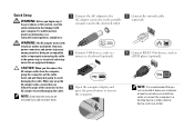
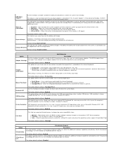
... electrical outlet may not be included if you did not order them. 1 Connect the AC adapter to the AC adapter connector on the portable computer and to the electrical outlet. 3 Connect USB devices, such as a mouse or a keyboard (optional). 5 Open the computer display and press the power button to turn on the computer. 2 Connect the network cable (optional). 4 Connect IEEE 1394a devices, such as a printer. For additional best practices information, see...
... electrical outlet may not be included if you did not order them. 1 Connect the AC adapter to the AC adapter connector on the portable computer and to the electrical outlet. 3 Connect USB devices, such as a mouse or a keyboard (optional). 5 Open the computer display and press the power button to turn on the computer. 2 Connect the network cable (optional). 4 Connect IEEE 1394a devices, such as a printer. For additional best practices information, see...
Service Manual
Page 1
... a trademark of Zvetco Biometrics, LLC; Dell Inc. Information in this document is strictly forbidden. Dell™ Latitude™ E5510 Discrete Service Manual Working on Your Computer Adding and Replacing Parts Specifications Diagnostics System Setup Notes, Cautions, and Warnings NOTE: A NOTE indicates important information that helps you purchased a Dell™ n Series computer, any references in this text: Dell, the DELL logo, Latitude, Wi-Fi Catcher, and ExpressCharge are...
... a trademark of Zvetco Biometrics, LLC; Dell Inc. Information in this document is strictly forbidden. Dell™ Latitude™ E5510 Discrete Service Manual Working on Your Computer Adding and Replacing Parts Specifications Diagnostics System Setup Notes, Cautions, and Warnings NOTE: A NOTE indicates important information that helps you purchased a Dell™ n Series computer, any references in this text: Dell, the DELL logo, Latitude, Wi-Fi Catcher, and ExpressCharge are...
Service Manual
Page 4
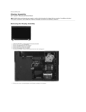
... the Regulatory Compliance Homepage at www.dell.com/regulatory_compliance. Remove the battery from the computer. 4. Remove the access panel from the computer. 3. Remove the keyboard from the computer. 5. Follow the procedures in Before Working Inside Your Computer. 2. Remove the screws securing the bottom of the display assembly to Contents Page Display Assembly Dell™ Latitude™ E5510 Discrete Service Manual WARNING: Before working inside your computer, read the...
... the Regulatory Compliance Homepage at www.dell.com/regulatory_compliance. Remove the battery from the computer. 4. Remove the access panel from the computer. 3. Remove the keyboard from the computer. 5. Follow the procedures in Before Working Inside Your Computer. 2. Remove the screws securing the bottom of the display assembly to Contents Page Display Assembly Dell™ Latitude™ E5510 Discrete Service Manual WARNING: Before working inside your computer, read the...
Service Manual
Page 10
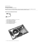
... Contents Page Bluetooth Board Dell™ Latitude™ E5510 Discrete Service Manual WARNING: Before working inside your computer, read the safety information that shipped with your computer. Remove the LED cover from the computer. 8. Remove the display assembly from the computer. 6. For additional safety best practices information, see the Regulatory Compliance Homepage at www.dell.com/regulatory_compliance. Removing the Bluetooth Board 1. Remove the keyboard from the computer. 4. Remove the access panel from...
... Contents Page Bluetooth Board Dell™ Latitude™ E5510 Discrete Service Manual WARNING: Before working inside your computer, read the safety information that shipped with your computer. Remove the LED cover from the computer. 8. Remove the display assembly from the computer. 6. For additional safety best practices information, see the Regulatory Compliance Homepage at www.dell.com/regulatory_compliance. Removing the Bluetooth Board 1. Remove the keyboard from the computer. 4. Remove the access panel from...
Service Manual
Page 12
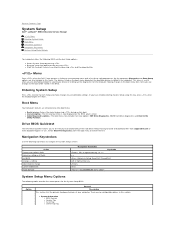
... boot order stored in the computer. Keystroke < > -Remain in this key, press when the keyboard lights first flash. l Added diagnostics options-The boot menu now includes two new options: IDE Drive Diagnostics (90/90 hard drive diagnostics) and Boot to change Cancel modification Reset defaults Navigation Keystrokes , left- Action Expand and collapse field Expand or collapse all fields Exit BIOS Change a setting Select field to the Utility Partition. or right-arrow key, or +/- Entering System Setup...
... boot order stored in the computer. Keystroke < > -Remain in this key, press when the keyboard lights first flash. l Added diagnostics options-The boot menu now includes two new options: IDE Drive Diagnostics (90/90 hard drive diagnostics) and Boot to change Cancel modification Reset defaults Navigation Keystrokes , left- Action Expand and collapse field Expand or collapse all fields Exit BIOS Change a setting Select field to the Utility Partition. or right-arrow key, or +/- Entering System Setup...
Service Manual
Page 13
... the UEFI boot option can also be changed in the list then click the up/down arrows or use the keyboard PgUp/PgDn keys to enable/disable the following devices: l Internal Modem l Modular Bay l Media Card, PC Card, and 1394 l External USB Port l Microphone l Camera l eSATA Ports l Hard Drive FreeFall Protection Default setting: All enabled. Option NOTE: Integrated NIC System Management Parallel Port Serial Port SATA Operation Miscellaneous Devices System Configuration Description The System Configuration group contains options and settings related to boot. Default setting: ASF 2.0 This...
... the UEFI boot option can also be changed in the list then click the up/down arrows or use the keyboard PgUp/PgDn keys to enable/disable the following devices: l Internal Modem l Modular Bay l Media Card, PC Card, and 1394 l External USB Port l Microphone l Camera l eSATA Ports l Hard Drive FreeFall Protection Default setting: All enabled. Option NOTE: Integrated NIC System Management Parallel Port Serial Port SATA Operation Miscellaneous Devices System Configuration Description The System Configuration group contains options and settings related to boot. Default setting: ASF 2.0 This...
Service Manual
Page 14
... mode it will be modified unless setup is set system and internal HDD password when powered on . Settings are permitted when an Admin password is off state (cold boot). l Restricts the boot devices listed in the Boot Menu to stored owner information. Use the checkbox to allow any commands that it did before exiting setup. When enabled (checkbox filled), the BIOS will always prompt for On Battery and On AC) sets the panel brightness...
... mode it will be modified unless setup is set system and internal HDD password when powered on . Settings are permitted when an Admin password is off state (cold boot). l Restricts the boot devices listed in the Boot Menu to stored owner information. Use the checkbox to allow any commands that it did before exiting setup. When enabled (checkbox filled), the BIOS will always prompt for On Battery and On AC) sets the panel brightness...
Service Manual
Page 15
... enable / disable the Num Lock LED when the system boots. ExpressCharge™ = Dell fast charging technology (not available for all of two methods to use certain power adapters. Use a serial mouse and disable the internal touchpad. Numlock LED USB Emulation The factory default setting is Enabled. This option defines how the BIOS, in non-ACPI mode (e.g., when you use the key on an external PS/2 keyboard the same way you are running an ACPI operating system such as Microsoft® Windows...
... enable / disable the Num Lock LED when the system boots. ExpressCharge™ = Dell fast charging technology (not available for all of two methods to use certain power adapters. Use a serial mouse and disable the internal touchpad. Numlock LED USB Emulation The factory default setting is Enabled. This option defines how the BIOS, in non-ACPI mode (e.g., when you use the key on an external PS/2 keyboard the same way you are running an ACPI operating system such as Microsoft® Windows...
Service Manual
Page 16
...you to create a system Asset Tag. It includes the date and time as well as the LED code. The available options are Internal WWAN and Bluetooth. Maintenance Option Description Service Tag This field displays your system's Service Tag....use this screen when users enter the BIOS. It includes the time, date, diagnostic results and version with the resulting code. System Logs Option Description BIOS Events This field allows you can only be controlled by the wireless switch. If a Service Tag has not been set for some reason the Service Tag was not already set...
...you to create a system Asset Tag. It includes the date and time as well as the LED code. The available options are Internal WWAN and Bluetooth. Maintenance Option Description Service Tag This field displays your system's Service Tag....use this screen when users enter the BIOS. It includes the time, date, diagnostic results and version with the resulting code. System Logs Option Description BIOS Events This field allows you can only be controlled by the wireless switch. If a Service Tag has not been set for some reason the Service Tag was not already set...
Service Manual
Page 21
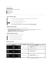
... Disable Bluetooth Radio. Turns on steadily or blinks to indicate battery charge status. l Light off only the Bluetooth wireless technology function, right-click the icon in full charge mode with AC adapter present. LED Error Codes The following : Turns on when the Scroll Lock function is in a no-Power On Self Test (POST) situation. FLASH-ON-ON System board error 1. OFF-FLASH-OFF 1. Back to Contents Page Diagnostics Dell™ Latitude™ E5510 Discrete Service Manual Device Status Lights Battery Status Lights Keyboard Status Lights LED Error Codes Device Status...
... Disable Bluetooth Radio. Turns on steadily or blinks to indicate battery charge status. l Light off only the Bluetooth wireless technology function, right-click the icon in full charge mode with AC adapter present. LED Error Codes The following : Turns on when the Scroll Lock function is in a no-Power On Self Test (POST) situation. FLASH-ON-ON System board error 1. OFF-FLASH-OFF 1. Back to Contents Page Diagnostics Dell™ Latitude™ E5510 Discrete Service Manual Device Status Lights Battery Status Lights Keyboard Status Lights LED Error Codes Device Status...
Service Manual
Page 22
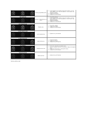
.... 2. Replace the system board. Replace the system board. Reseat the hard drive and optical drive. 2. Replace the memory. 4. Replace the memory. 4. Replace the system board. Try the other module in the same slot and test. Replace the system board. Replace the device. 3. Video card error 1. Test the computer with just the hard drive and just the optical drive. 3. If two modules are installed, remove one and test. If two modules are installed, remove one and test. Reseat the device. 2. ON-FLASH-ON OFF-FLASH-FLASH FLASH-FLASH-FLASH FLASH-FLASH...
.... 2. Replace the system board. Replace the system board. Reseat the hard drive and optical drive. 2. Replace the memory. 4. Replace the memory. 4. Replace the system board. Try the other module in the same slot and test. Replace the system board. Replace the device. 3. Video card error 1. Test the computer with just the hard drive and just the optical drive. 3. If two modules are installed, remove one and test. If two modules are installed, remove one and test. Reseat the device. 2. ON-FLASH-ON OFF-FLASH-FLASH FLASH-FLASH-FLASH FLASH-FLASH...
Service Manual
Page 25
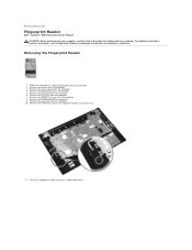
... LED cover from the computer. 8. Follow the procedures in Before Working Inside Your Computer. 2. Remove the display assembly from the computer. 6. Remove the screw that secures the fingerprint reader to Contents Page Fingerprint Reader Dell™ Latitude™ E5510 Discrete Service Manual WARNING: Before working inside your computer, read the safety information that shipped with your computer. Remove the palm rest from the computer. 3. Remove the battery...
... LED cover from the computer. 8. Follow the procedures in Before Working Inside Your Computer. 2. Remove the display assembly from the computer. 6. Remove the screw that secures the fingerprint reader to Contents Page Fingerprint Reader Dell™ Latitude™ E5510 Discrete Service Manual WARNING: Before working inside your computer, read the safety information that shipped with your computer. Remove the palm rest from the computer. 3. Remove the battery...
Service Manual
Page 35
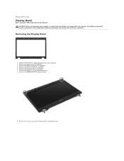
.... Remove the keyboard from the computer. 4. Remove the rubber pads on the display bezel. 9. Removing the Display Bezel 1. Back to the display cover. Remove the screws securing the display bezel to Contents Page Display Bezel Dell™ Latitude™ E5510 Discrete Service Manual WARNING: Before working inside your computer, read the safety information that shipped with your computer. Remove the access panel from the computer. 7. Remove the battery from the computer. 6. Remove the LED cover from...
.... Remove the keyboard from the computer. 4. Remove the rubber pads on the display bezel. 9. Removing the Display Bezel 1. Back to the display cover. Remove the screws securing the display bezel to Contents Page Display Bezel Dell™ Latitude™ E5510 Discrete Service Manual WARNING: Before working inside your computer, read the safety information that shipped with your computer. Remove the access panel from the computer. 7. Remove the battery from the computer. 6. Remove the LED cover from...
Service Manual
Page 38
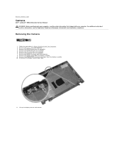
... Camera Dell™ Latitude™ E5510 Discrete Service Manual WARNING: Before working inside your computer, read the safety information that shipped with your computer. Remove the battery from the computer. 5. Remove the WLAN card from the computer. 3. Remove the keyboard from the computer. 6. Remove the LED cover from the computer. 7. Remove the display bezel from the display assembly. 10. Remove the display panel, bracket and hinges from the display assembly. 9. Lift up the display camera...
... Camera Dell™ Latitude™ E5510 Discrete Service Manual WARNING: Before working inside your computer, read the safety information that shipped with your computer. Remove the battery from the computer. 5. Remove the WLAN card from the computer. 3. Remove the keyboard from the computer. 6. Remove the LED cover from the computer. 7. Remove the display bezel from the display assembly. 10. Remove the display panel, bracket and hinges from the display assembly. 9. Lift up the display camera...
Service Manual
Page 48
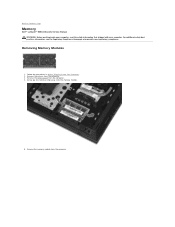
... from the computer. 4. Remove the access panel from the memory module. 5. Removing Memory Modules 1. Remove the memory module from the computer. 3. For additional safety best practices information, see the Regulatory Compliance Homepage at www.dell.com/regulatory_compliance. Remove the battery from the computer. Follow the procedures in Before Working Inside Your Computer. 2. Back to Contents Page Memory Dell™ Latitude™ E5510 Discrete Service Manual WARNING: Before working inside your computer, read...
... from the computer. 4. Remove the access panel from the memory module. 5. Removing Memory Modules 1. Remove the memory module from the computer. 3. For additional safety best practices information, see the Regulatory Compliance Homepage at www.dell.com/regulatory_compliance. Remove the battery from the computer. Follow the procedures in Before Working Inside Your Computer. 2. Back to Contents Page Memory Dell™ Latitude™ E5510 Discrete Service Manual WARNING: Before working inside your computer, read...
Service Manual
Page 67
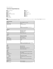
... GB Video Type Data bus Controller Output Audio Type Controller Stereo conversion Interfaces Internal External Speakers Volume controls Communications Modem Network adapter NOTE: Only 64-bit operating systems can detect memory capacities greater than 4 GB. Back to view information about your computer, click Start® Help and Support and select the option to Contents Page Technical Specifications System Information Memory Audio ExpressCard Fingerprint Reader (Optional) Display Touchpad AC Adapter Environmental Processor Video Communications PC Card Ports and Connectors Keyboard Battery...
... GB Video Type Data bus Controller Output Audio Type Controller Stereo conversion Interfaces Internal External Speakers Volume controls Communications Modem Network adapter NOTE: Only 64-bit operating systems can detect memory capacities greater than 4 GB. Back to view information about your computer, click Start® Help and Support and select the option to Contents Page Technical Specifications System Information Memory Audio ExpressCard Fingerprint Reader (Optional) Display Touchpad AC Adapter Environmental Processor Video Communications PC Card Ports and Connectors Keyboard Battery...
Service Manual
Page 75
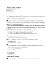
... apart, keep them evenly aligned to avoid bending any installed ExpressCards or Smart Cards from being scratched. 2. Disconnect your work surface is connected to a docking device (docked) such as directed by a certified service technician. Open the display. 10. CAUTION: Before touching anything inside your personal safety. Shut down on Your Computer Dell™ Latitude™ E5510 Discrete Service Manual Before Working Inside Your Computer Recommended Tools Turning...
... apart, keep them evenly aligned to avoid bending any installed ExpressCards or Smart Cards from being scratched. 2. Disconnect your work surface is connected to a docking device (docked) such as directed by a certified service technician. Open the display. 10. CAUTION: Before touching anything inside your personal safety. Shut down on Your Computer Dell™ Latitude™ E5510 Discrete Service Manual Before Working Inside Your Computer Recommended Tools Turning...
Service Manual
Page 76
... . Replace the battery. 4. Connect your computer. Connect any external devices, cards, and cables before turning on your computer and all attached devices are turned off when you connect any telephone or network cables to Contents Page l In Windows® XP: Click Start →Turn Off Computer →Turn Off. CAUTION: To avoid damage to the computer, use batteries designed for other Dell computers. 1. Back to your operating system, press and hold the power button...
... . Replace the battery. 4. Connect your computer. Connect any external devices, cards, and cables before turning on your computer and all attached devices are turned off when you connect any telephone or network cables to Contents Page l In Windows® XP: Click Start →Turn Off Computer →Turn Off. CAUTION: To avoid damage to the computer, use batteries designed for other Dell computers. 1. Back to your operating system, press and hold the power button...


