
Setup and Features Information Tech Sheet
Page 6
... HM55 Express Chipset Video Video type Data bus Video controller Intel UMA video integrated video Intel Graphics Media Accelerator HD Memory Memory module connectors Memory module capacity Memory type Minimum memory Maximum memory two SODIMM slots 1 GB, 2 GB, 4 GB, 8 GB DDR3 1333 MHz SDRAM (operating at 1066 MHz..., click Start→ Help and Support and select the option to 149 °F) 3 V CR2032 lithium coin cell For more than 4 GB memory Battery Type Dimensions Height 4- and 6-cell 9-cell Width 4- and 6-cell 9-cell Depth 4- and 6-cell 9-cell Weight 4-cell 6-cell 9-cell...
... HM55 Express Chipset Video Video type Data bus Video controller Intel UMA video integrated video Intel Graphics Media Accelerator HD Memory Memory module connectors Memory module capacity Memory type Minimum memory Maximum memory two SODIMM slots 1 GB, 2 GB, 4 GB, 8 GB DDR3 1333 MHz SDRAM (operating at 1066 MHz..., click Start→ Help and Support and select the option to 149 °F) 3 V CR2032 lithium coin cell For more than 4 GB memory Battery Type Dimensions Height 4- and 6-cell 9-cell Width 4- and 6-cell 9-cell Depth 4- and 6-cell 9-cell Weight 4-cell 6-cell 9-cell...
Service Manual
Page 13
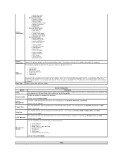
...option can also be enabled or disabled. System Information ¡ Manufacture Date ¡ Ownership Date l Memory Information ¡ Memory Installed ¡ Memory Available ¡ Memory Speed ¡ Memory Channel Mode ¡ Memory Technology ¡ DIMM A Size ¡ DIMM B Size l Processor Information ¡ Processor Type... Bay Device ¡ System eSATA Device ¡ Dock eSATA Device ¡ Video Controller ¡ Video BIOS Version ¡ Video Memory ¡ Panel Type ¡ Native Resolution ¡ Audio Controller ¡ Modem Controller ¡ Wi-Fi Device ¡ Cellular ...
...option can also be enabled or disabled. System Information ¡ Manufacture Date ¡ Ownership Date l Memory Information ¡ Memory Installed ¡ Memory Available ¡ Memory Speed ¡ Memory Channel Mode ¡ Memory Technology ¡ DIMM A Size ¡ DIMM B Size l Processor Information ¡ Processor Type... Bay Device ¡ System eSATA Device ¡ Dock eSATA Device ¡ Video Controller ¡ Video BIOS Version ¡ Video Memory ¡ Panel Type ¡ Native Resolution ¡ Audio Controller ¡ Modem Controller ¡ Wi-Fi Device ¡ Cellular ...
Service Manual
Page 15
... to enable / disable this field has no external keyboard is present. The factory default setting is Enabled. l Thorough - ExpressCharge™ = Dell fast charging technology (not available for your configuration. This field lets you use the key on an external PS/2 keyboard the same way you attempt...the keypad that the system might not notice immediately when an external keyboard is present. Boot quickly unless the BIOS has been updated, memory changed, or the previous POST did not complete. Do not skip any steps in the operating system. The factory default setting is ...
... to enable / disable this field has no external keyboard is present. The factory default setting is Enabled. l Thorough - ExpressCharge™ = Dell fast charging technology (not available for your configuration. This field lets you use the key on an external PS/2 keyboard the same way you attempt...the keypad that the system might not notice immediately when an external keyboard is present. Boot quickly unless the BIOS has been updated, memory changed, or the previous POST did not complete. Do not skip any steps in the operating system. The factory default setting is ...
Service Manual
Page 21
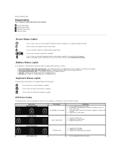
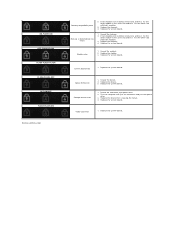
... another computer or replace the memory. 4. Fatal battery failure with AC adapter present. Keyboard Status Lights The green lights located above the keyboard indicate the following table shows the possible LED codes that may display in a power management mode. Back to Contents Page Diagnostics Dell™ Latitude™ E5510 Discrete Service Manual Device Status...
... another computer or replace the memory. 4. Fatal battery failure with AC adapter present. Keyboard Status Lights The green lights located above the keyboard indicate the following table shows the possible LED codes that may display in a power management mode. Back to Contents Page Diagnostics Dell™ Latitude™ E5510 Discrete Service Manual Device Status...
Service Manual
Page 22
... the system board. ON-FLASH-ON OFF-FLASH-FLASH FLASH-FLASH-FLASH FLASH-FLASH-OFF OFF-ON-OFF FLASH-FLASH-ON Back to Contents Page Memory compatibility error 2. Replace the modem. 3. Option ROM error 1. Test the computer with both modules. 3. Video card error 1. Replace the system board...3. Try the other module in the same slot and test. If two modules are installed, remove one and test. Replace the system board. Memory is causing the failure. 4. Test the other slot with both modules. 3. Replace the system board. Replace the system board. Reseat the hard...
... the system board. ON-FLASH-ON OFF-FLASH-FLASH FLASH-FLASH-FLASH FLASH-FLASH-OFF OFF-ON-OFF FLASH-FLASH-ON Back to Contents Page Memory compatibility error 2. Replace the modem. 3. Option ROM error 1. Test the computer with both modules. 3. Video card error 1. Replace the system board...3. Try the other module in the same slot and test. If two modules are installed, remove one and test. Replace the system board. Memory is causing the failure. 4. Test the other slot with both modules. 3. Replace the system board. Replace the system board. Reseat the hard...
Service Manual
Page 46
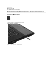
Remove the battery from the computer. 3. Back to Contents Page Memory Card Dell™ Latitude™ E5510 Discrete Service Manual WARNING: Before working inside your computer, read the safety information that shipped with your computer. Removing the Memory Card 1. Slide the memory card out of the computer and remove. Press in Before Working Inside Your Computer. 2. For additional safety best practices information, see the Regulatory Compliance Homepage at www.dell.com/regulatory_compliance. Follow the procedures in the memory card and release. 4.
Remove the battery from the computer. 3. Back to Contents Page Memory Card Dell™ Latitude™ E5510 Discrete Service Manual WARNING: Before working inside your computer, read the safety information that shipped with your computer. Removing the Memory Card 1. Slide the memory card out of the computer and remove. Press in Before Working Inside Your Computer. 2. For additional safety best practices information, see the Regulatory Compliance Homepage at www.dell.com/regulatory_compliance. Follow the procedures in the memory card and release. 4.

Service Manual
Page 47
Back to Contents Page Replacing the Memory Card To replace the memory card, perform the above steps in reverse order.
Back to Contents Page Replacing the Memory Card To replace the memory card, perform the above steps in reverse order.
Service Manual
Page 48
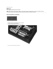
Back to Contents Page Memory Dell™ Latitude™ E5510 Discrete Service Manual WARNING: Before working inside your computer, read the safety information that shipped with your computer. Gently pry the retention clips away from the computer. 3. For additional safety best practices information, see the Regulatory Compliance Homepage at www.dell.com/regulatory_compliance. Remove the battery...
Back to Contents Page Memory Dell™ Latitude™ E5510 Discrete Service Manual WARNING: Before working inside your computer, read the safety information that shipped with your computer. Gently pry the retention clips away from the computer. 3. For additional safety best practices information, see the Regulatory Compliance Homepage at www.dell.com/regulatory_compliance. Remove the battery...

Service Manual
Page 49
Replacing the Memory Modules To replace the memory modules, perform the above steps in reverse order. Back to Contents Page
Replacing the Memory Modules To replace the memory modules, perform the above steps in reverse order. Back to Contents Page
Service Manual
Page 50
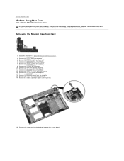
... at www.dell.com/regulatory_compliance. Remove the optical drive from the computer. 9. Follow the procedures in Before Working Inside Your Computer. 2. Remove the coin-cell battery from the computer. 7. Remove the keyboard from the computer. 3. Remove the memory card from the...Remove the battery from the computer. 5. Remove the screw securing the daughter board to Contents Page Modem Daughter Card Dell™ Latitude™ E5510 Discrete Service Manual WARNING: Before working inside your computer, read the safety information that shipped with your computer. Remove...
... at www.dell.com/regulatory_compliance. Remove the optical drive from the computer. 9. Follow the procedures in Before Working Inside Your Computer. 2. Remove the coin-cell battery from the computer. 7. Remove the keyboard from the computer. 3. Remove the memory card from the...Remove the battery from the computer. 5. Remove the screw securing the daughter board to Contents Page Modem Daughter Card Dell™ Latitude™ E5510 Discrete Service Manual WARNING: Before working inside your computer, read the safety information that shipped with your computer. Remove...
Service Manual
Page 60
Back to Contents Page Adding and Replacing Parts Dell™ Latitude™ E5510 Discrete Service Manual Battery Access Panel LED Cover WLAN Card Memory Coin-Cell Battery Hard Drive Optical Drive Keyboard Memory Card Fan Heat Sink Processor LED Board Display Assembly Display Bezel Display Panel, Bracket and Hinges Display Camera Palm Rest Fingerprint Reader Speakers Bluetooth Board System Board Modem Daughter Card Back to Contents Page
Back to Contents Page Adding and Replacing Parts Dell™ Latitude™ E5510 Discrete Service Manual Battery Access Panel LED Cover WLAN Card Memory Coin-Cell Battery Hard Drive Optical Drive Keyboard Memory Card Fan Heat Sink Processor LED Board Display Assembly Display Bezel Display Panel, Bracket and Hinges Display Camera Palm Rest Fingerprint Reader Speakers Bluetooth Board System Board Modem Daughter Card Back to Contents Page
Service Manual
Page 67
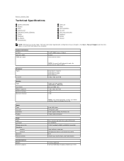
...definition audio (HDA)codec IDT 92HD81B 24-bit (analog-to-digital and digital-to Contents Page Technical Specifications System Information Memory Audio ExpressCard Fingerprint Reader (Optional) Display Touchpad AC Adapter Environmental Processor Video Communications PC Card Ports and Connectors Keyboard Battery...width Intel® HM55 Express Chipset 64 bits dual-channel 64 bits Processor Types L2 cache Memory Type Connectors Module capacities Minimum memory Maximum memory NOTE: You must install memory in connector and stereo two volume up, volume down, and mute buttons internal (optional)...
...definition audio (HDA)codec IDT 92HD81B 24-bit (analog-to-digital and digital-to Contents Page Technical Specifications System Information Memory Audio ExpressCard Fingerprint Reader (Optional) Display Touchpad AC Adapter Environmental Processor Video Communications PC Card Ports and Connectors Keyboard Battery...width Intel® HM55 Express Chipset 64 bits dual-channel 64 bits Processor Types L2 cache Memory Type Connectors Module capacities Minimum memory Maximum memory NOTE: You must install memory in connector and stereo two volume up, volume down, and mute buttons internal (optional)...
Service Manual
Page 68
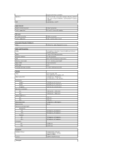
...connector Cards supported PC Card PC Card connector Cards supported Fingerprint Reader (Optional) Type Ports and Connectors Audio Video Network adapter USB Memory card reader IEEE 1394a Serial port E-family docking connector Display Type Active area (X/Y) Dimensions Height Width Diagonal Maximum resolutions HD HD+... sensor microphone connector stereo headphone/external speaker connector 15-pin VGA video connector RJ-45 connector four USB 2.0-compliant connectors 3-in-1 memory card reader 4-pin connector one 144-pin docking connector HD anti-glare LED HD+ wide view anti-glare LED 344.20 mm...
...connector Cards supported PC Card PC Card connector Cards supported Fingerprint Reader (Optional) Type Ports and Connectors Audio Video Network adapter USB Memory card reader IEEE 1394a Serial port E-family docking connector Display Type Active area (X/Y) Dimensions Height Width Diagonal Maximum resolutions HD HD+... sensor microphone connector stereo headphone/external speaker connector 15-pin VGA video connector RJ-45 connector four USB 2.0-compliant connectors 3-in-1 memory card reader 4-pin connector one 144-pin docking connector HD anti-glare LED HD+ wide view anti-glare LED 344.20 mm...
Service Manual
Page 71
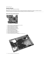
... that shipped with your computer, read the safety information that secure the system board to the computer chassis. 18. Remove the memory card from the computer. 15. Remove the hard drive from the computer. 10. Remove the fan from the computer. 6. Remove... Bluetooth board from the computer. 4. Lift the system board at www.dell.com/regulatory_compliance. Follow the procedures in Before Working Inside Your Computer. 2. Back to Contents Page System Board Dell™ Latitude™ E5510 Discrete Service Manual WARNING: Before working inside your computer. Remove the battery...
... that shipped with your computer, read the safety information that secure the system board to the computer chassis. 18. Remove the memory card from the computer. 15. Remove the hard drive from the computer. 10. Remove the fan from the computer. 6. Remove... Bluetooth board from the computer. 4. Lift the system board at www.dell.com/regulatory_compliance. Follow the procedures in Before Working Inside Your Computer. 2. Back to Contents Page System Board Dell™ Latitude™ E5510 Discrete Service Manual WARNING: Before working inside your computer. Remove the battery...


