
Quick Reference Guide
Page 12
... removed or the area is a component of the computer are protected from ingress by dense magnesium compartment doors. 1 Docking device connector door 2 4 Battery compartment cover Memory module cover 3 Hard disk drive compartment cover The compartments on the bottom of the Armored Protection System. Do not utilize any of the connectors/hubs...
... removed or the area is a component of the computer are protected from ingress by dense magnesium compartment doors. 1 Docking device connector door 2 4 Battery compartment cover Memory module cover 3 Hard disk drive compartment cover The compartments on the bottom of the Armored Protection System. Do not utilize any of the connectors/hubs...

Quick Reference Guide
Page 17
... is shown in the battery bay. For optimal computer performance and to , the following Using optical drives Using wireless communications devices, PC Cards, ExpressCards, media memory cards, or USB devices Using high-brightness display settings, 3D screen savers, or other power-intensive programs such as complex 3D graphics applications One battery...
... is shown in the battery bay. For optimal computer performance and to , the following Using optical drives Using wireless communications devices, PC Cards, ExpressCards, media memory cards, or USB devices Using high-brightness display settings, 3D screen savers, or other power-intensive programs such as complex 3D graphics applications One battery...

Quick Reference Guide
Page 22
...Dell Diagnostics from the diagnostics utility partition on . Press any key to run a complete test on your computer and try again. Shut down your computer. NOTE: The next steps change the boot sequence for your computer. Option Test Memory Test System Exit Function Run the stand-alone memory... for one time only. If multiple versions are detected during the Pre-boot System Assessment, write down the error code(s) and contact Dell. This typically can NOTE: If you wait too long and the operating system logo appears, continue to retest the component that appears ...
...Dell Diagnostics from the diagnostics utility partition on . Press any key to run a complete test on your computer and try again. Shut down your computer. NOTE: The next steps change the boot sequence for your computer. Option Test Memory Test System Exit Function Run the stand-alone memory... for one time only. If multiple versions are detected during the Pre-boot System Assessment, write down the error code(s) and contact Dell. This typically can NOTE: If you wait too long and the operating system logo appears, continue to retest the component that appears ...

Quick Reference Guide
Page 23
... problem is located on your computer or all devices from the system setup program, memory, and various internal tests, and it displays the information in the device list in the system. If you contact Dell, technical support will ask for running the test. This option lists the most common...Errors Help Configuration Function Displays the results of the screen. Allows you are completed, close the Main Menu screen. 6. To exit the Dell Diagnostics and restart the computer, close the test screen to return to be run a test from the Custom Test or Symptom Tree option,...
... problem is located on your computer or all devices from the system setup program, memory, and various internal tests, and it displays the information in the device list in the system. If you contact Dell, technical support will ask for running the test. This option lists the most common...Errors Help Configuration Function Displays the results of the screen. Allows you are completed, close the Main Menu screen. 6. To exit the Dell Diagnostics and restart the computer, close the test screen to return to be run a test from the Custom Test or Symptom Tree option,...
Service Manual
Page 3
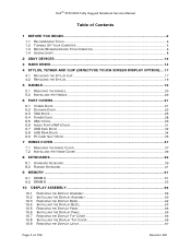
DellTM XFR D630 Fully Rugged Notebook Service Manual Table of Contents 1 BEFORE YOU BEGIN ...6 1.1 RECOMMENDED TOOLS ...6 1.2 TURNING OFF YOUR COMPUTER 6 1.3 BEFORE WORKING INSIDE YOUR COMPUTER 6 1.4 SCREW CHART ...8 2 XBAY ... CARD SLOT DOOR ...35 7 HINGE COVER ...37 7.1 REMOVING THE HINGE COVER 37 7.2 INSTALLING THE HINGE COVER 39 8 KEYBOARDS ...39 8.1 STANDARD KEYBOARD ...39 8.2 RUGGED KEYBOARD ...41 9 MEMORY ...51 9.1 DIMM A ...51 9.2 DIMM B ...53 10 DISPLAY ASSEMBLY 55 10.1 10.2 10.3 10.4 10.5 10.6 10.7 10.8 10.9 REMOVING THE DISPLAY ASSEMBLY 56 INSTALLING THE...
DellTM XFR D630 Fully Rugged Notebook Service Manual Table of Contents 1 BEFORE YOU BEGIN ...6 1.1 RECOMMENDED TOOLS ...6 1.2 TURNING OFF YOUR COMPUTER 6 1.3 BEFORE WORKING INSIDE YOUR COMPUTER 6 1.4 SCREW CHART ...8 2 XBAY ... CARD SLOT DOOR ...35 7 HINGE COVER ...37 7.1 REMOVING THE HINGE COVER 37 7.2 INSTALLING THE HINGE COVER 39 8 KEYBOARDS ...39 8.1 STANDARD KEYBOARD ...39 8.2 RUGGED KEYBOARD ...41 9 MEMORY ...51 9.1 DIMM A ...51 9.2 DIMM B ...53 10 DISPLAY ASSEMBLY 55 10.1 10.2 10.3 10.4 10.5 10.6 10.7 10.8 10.9 REMOVING THE DISPLAY ASSEMBLY 56 INSTALLING THE...
Service Manual
Page 51
...your computer may have, even if you remove your computer has only one accessed from beneath the keyboard (DIMM A), and the other accessed from Dell. NOTICE: To avoid electrostatic discharge, ground yourself by using a wrist grounding strap or by periodically touching an unpainted metal surface (such as ...the keyboard (see Removing the Hinge Cover). 106H 3. Otherwise, your computer warranty. Your computer has two user-accessible SODIMM sockets, one memory module, install the memory module in the XFR D630 User's Guide. DellTM XFR D630 Fully Rugged Notebook Service Manual 12.
...your computer may have, even if you remove your computer has only one accessed from beneath the keyboard (DIMM A), and the other accessed from Dell. NOTICE: To avoid electrostatic discharge, ground yourself by using a wrist grounding strap or by periodically touching an unpainted metal surface (such as ...the keyboard (see Removing the Hinge Cover). 106H 3. Otherwise, your computer warranty. Your computer has two user-accessible SODIMM sockets, one memory module, install the memory module in the XFR D630 User's Guide. DellTM XFR D630 Fully Rugged Notebook Service Manual 12.
Service Manual
Page 52
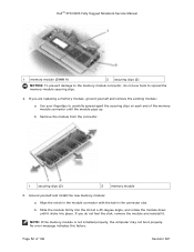
... notch in the module connector with the tab in the connector slot. Remove the module from the connector. 1 securing clips (2) 2 memory module 5. Use your fingertips to carefully spread apart the securing clips on each end of 106 Revision A01 No error message indicates this... failure. Page 52 of the memory module connector until it . Slide the module firmly into place. DellTM XFR D630 Fully Rugged Notebook Service Manual 1 memory module (DIMM A) 2 securing clips (2) NOTICE: To prevent damage to the memory module connector, do not feel the click, remove...
... notch in the module connector with the tab in the connector slot. Remove the module from the connector. 1 securing clips (2) 2 memory module 5. Use your fingertips to carefully spread apart the securing clips on each end of 106 Revision A01 No error message indicates this... failure. Page 52 of the memory module connector until it . Slide the module firmly into place. DellTM XFR D630 Fully Rugged Notebook Service Manual 1 memory module (DIMM A) 2 securing clips (2) NOTICE: To prevent damage to the memory module connector, do not feel the click, remove...

Service Manual
Page 53
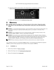
... at a 45-degree angle to install memory modules in two connectors, install a memory module in the connector labeled "DIMM A" before you need to avoid damaging the connector. 1. Replace the hinge cover (see Keyboards). 108H 7. Follow the procedures in ... Cover). 109H 9.2 DIMM B NOTICE: If you install a module in Before You Begin. 10H 2. Turn the computer bottom-side up, remove the 4 screws that secure the memory module cover, and then remove the cover. DellTM XFR D630 Fully Rugged Notebook Service Manual 1 tab 2 notch 6.
... at a 45-degree angle to install memory modules in two connectors, install a memory module in the connector labeled "DIMM A" before you need to avoid damaging the connector. 1. Replace the hinge cover (see Keyboards). 108H 7. Follow the procedures in ... Cover). 109H 9.2 DIMM B NOTICE: If you install a module in Before You Begin. 10H 2. Turn the computer bottom-side up, remove the 4 screws that secure the memory module cover, and then remove the cover. DellTM XFR D630 Fully Rugged Notebook Service Manual 1 tab 2 notch 6.

Service Manual
Page 54
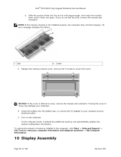
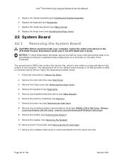
... connector until the module pops up. DellTM XFR D630 Fully Rugged Notebook Service Manual 1 3 2 1 Screws (4) 2 Memory module cover 3 Memory module compartment NOTICE: To prevent damage to the memory module connector, do not use tools to avoid damaging the connector. 4. Align the notch in the module edge connector with the tab in... slot. b. Use your fingertips to carefully spread apart the securing clips on each end of 106 Revision A01 If you are replacing a memory module, ground yourself and remove the existing module: a. Remove the module from the connector. 1 securing clips...
... connector until the module pops up. DellTM XFR D630 Fully Rugged Notebook Service Manual 1 3 2 1 Screws (4) 2 Memory module cover 3 Memory module compartment NOTICE: To prevent damage to the memory module connector, do not use tools to avoid damaging the connector. 4. Align the notch in the module edge connector with the tab in... slot. b. Use your fingertips to carefully spread apart the securing clips on each end of 106 Revision A01 If you are replacing a memory module, ground yourself and remove the existing module: a. Remove the module from the connector. 1 securing clips...
Service Manual
Page 55
DellTM XFR D630 Fully Rugged Notebook Service Manual b. If you do not feel the click, remove the module and reinstall it detects the additional memory and automatically updates the system configuration information. NOTICE: If the cover is not installed properly, the computer may damage your ...computer. 6. As the computer boots, it . No error message indicates this failure. 1 tab 2 notch 5. Replace the memory module cover, and use the 4 screws to your computer information and diagnose problems -> My Computer Information. 10 Display Assembly Page 55 of 106 ...
DellTM XFR D630 Fully Rugged Notebook Service Manual b. If you do not feel the click, remove the module and reinstall it detects the additional memory and automatically updates the system configuration information. NOTICE: If the cover is not installed properly, the computer may damage your ...computer. 6. As the computer boots, it . No error message indicates this failure. 1 tab 2 notch 5. Replace the memory module cover, and use the 4 screws to your computer information and diagnose problems -> My Computer Information. 10 Display Assembly Page 55 of 106 ...
Service Manual
Page 95
... of the computer. Remove the memory module(s) (see XBay Devices). 26H 6. Remove any installed media bay device (see Memory). 267H 7. Remove the keyboard (see Installing the Display Assembly). 258H 6. Replace the display assembly (see Keyboards). 265H 5. DellTM XFR D630 Fully Rugged Notebook Service Manual 5....22 System Board 22.1 Removing the System Board CAUTION: Before working inside your computer, follow the safety instructions in the XFR D630 Product Information Guide and in Before You Begin. 26H 2. Remove any installed smart cards or smart card blanks from the...
... of the computer. Remove the memory module(s) (see XBay Devices). 26H 6. Remove any installed media bay device (see Memory). 267H 7. Remove the keyboard (see Installing the Display Assembly). 258H 6. Replace the display assembly (see Keyboards). 265H 5. DellTM XFR D630 Fully Rugged Notebook Service Manual 5....22 System Board 22.1 Removing the System Board CAUTION: Before working inside your computer, follow the safety instructions in the XFR D630 Product Information Guide and in Before You Begin. 26H 2. Remove any installed smart cards or smart card blanks from the...

Service Manual
Page 100
... (see Installing the Hinge Cover). 289H 17. Install the hinge cover (see Memory). 286H 14. Install the processor (see Installing the Speaker). 281H 11. Install the speaker (see Installing the Processor). 278H 7. Install any media bay devices (...Devices). 287H 15. Reconnect the fan cable to the system board. 5. Install any smart cards or smart card blanks into the smart card slot. 9. DellTM XFR D630 Fully Rugged Notebook Service Manual Ensure cables are correctly positioned. 3. Install the keyboard (see WWAN, FCM & SIM Cards, Wireless Local Area 28H 283H Network (...
... (see Installing the Hinge Cover). 289H 17. Install the hinge cover (see Memory). 286H 14. Install the processor (see Installing the Speaker). 281H 11. Install the speaker (see Installing the Processor). 278H 7. Install any media bay devices (...Devices). 287H 15. Reconnect the fan cable to the system board. 5. Install any smart cards or smart card blanks into the smart card slot. 9. DellTM XFR D630 Fully Rugged Notebook Service Manual Ensure cables are correctly positioned. 3. Install the keyboard (see WWAN, FCM & SIM Cards, Wireless Local Area 28H 283H Network (...

Service Manual
Page 102
... periodically touching an unpainted metal surface (such as the downloaded BIOS update file. 9. Follow the instructions in the XFR D630 User's Guide. Page 102 of the computer). 1. Click Download Now to view the Save In menu, select ... appears, click Yes, I Accept this program to your computer, follow the instructions on your computer at support.dell.com. 4. Click Close if the Download Complete window appears. Click the down arrow to download the file. ...NOTE: When removing the system board, do not remove the system memory, processor thermalcooling assembly or the processor.
... periodically touching an unpainted metal surface (such as the downloaded BIOS update file. 9. Follow the instructions in the XFR D630 User's Guide. Page 102 of the computer). 1. Click Download Now to view the Save In menu, select ... appears, click Yes, I Accept this program to your computer, follow the instructions on your computer at support.dell.com. 4. Click Close if the Download Complete window appears. Click the down arrow to download the file. ...NOTE: When removing the system board, do not remove the system memory, processor thermalcooling assembly or the processor.

Service Manual
Page 104
DellTM XFR D630 Fully Rugged Notebook Service Manual 3. NOTICE: To avoid electrostatic discharge, ground yourself by using a wrist grounding strap or by periodically touching an unpainted metal surface (...: Before working inside your computer, follow the safety instructions in the XFR D630 Product Information Guide and in Before You Begin. 296H 2. Refer to the antenna cable wiring diagram to remove the system memory or the processor. 3. Follow the instructions in the XFR D630 User's Guide. Remove the modem cable (see Removing the Modem Cable...
DellTM XFR D630 Fully Rugged Notebook Service Manual 3. NOTICE: To avoid electrostatic discharge, ground yourself by using a wrist grounding strap or by periodically touching an unpainted metal surface (...: Before working inside your computer, follow the safety instructions in the XFR D630 Product Information Guide and in Before You Begin. 296H 2. Refer to the antenna cable wiring diagram to remove the system memory or the processor. 3. Follow the instructions in the XFR D630 User's Guide. Remove the modem cable (see Removing the Modem Cable...

Service Manual
Page 105
...105 of the computer). 1. Remove the system board (see the proper cable routing and where to secure the cable to remove the system memory or the processor. 3. Refer to the figure below to see Removing the System Board). 307H NOTE: When removing the system board you... Begin. 306H 2. Install the shoulder strap anchors if previously removed. 2. Replace the fan (see Installing the RF Passthru Board). 30H 4. DellTM XFR D630 Fully Rugged Notebook Service Manual 6. Replace the modem cable (see Stylus, Tether and Clip). 301H 25.2 Installing the Bottom Chassis NOTE: The replacement...
...105 of the computer). 1. Remove the system board (see the proper cable routing and where to secure the cable to remove the system memory or the processor. 3. Refer to the figure below to see Removing the System Board). 307H NOTE: When removing the system board you... Begin. 306H 2. Install the shoulder strap anchors if previously removed. 2. Replace the fan (see Installing the RF Passthru Board). 30H 4. DellTM XFR D630 Fully Rugged Notebook Service Manual 6. Replace the modem cable (see Stylus, Tether and Clip). 301H 25.2 Installing the Bottom Chassis NOTE: The replacement...
User's Guide
Page 3
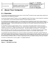
... also means operating system images, drivers, firmware and other items controlled by Dell QuickSet 2 About Your Computer information, see "Dell QuickSet". 12H 2.1 Overview The XFR D630 Fully Rugged Notebook provides Xtreme Terrain GradeTM protection through rugged design expertise and independent... and conductive cooling focused on the internal core system components, primary memory, storage and smart battery elements. With the XFR D630, you with DellTM's LatitudeTM D630 and ATGTM D630 notebooks, thereby simplifying IT management and reducing support and administrative time and...
... also means operating system images, drivers, firmware and other items controlled by Dell QuickSet 2 About Your Computer information, see "Dell QuickSet". 12H 2.1 Overview The XFR D630 Fully Rugged Notebook provides Xtreme Terrain GradeTM protection through rugged design expertise and independent... and conductive cooling focused on the internal core system components, primary memory, storage and smart battery elements. With the XFR D630, you with DellTM's LatitudeTM D630 and ATGTM D630 notebooks, thereby simplifying IT management and reducing support and administrative time and...

User's Guide
Page 14
...the documentation that came with your computer to be non-hazardous WARNING - 1 Docking device connector cover 2 4 Battery compartment cover 5 Memory module cover 3 XBay device locking screw Hard disk drive compartment cover The compartments on the bottom of the battery, see "Using ...for 138H additional information. 2.6.4 Battery Compartment Cover The battery compartment cover provides a cover for the compartment that contains the second memory module connector (DIMM B) (see "XBay"). 140H Explosion Hazard - For additional information regarding the use and access of the computer...
...the documentation that came with your computer to be non-hazardous WARNING - 1 Docking device connector cover 2 4 Battery compartment cover 5 Memory module cover 3 XBay device locking screw Hard disk drive compartment cover The compartments on the bottom of the battery, see "Using ...for 138H additional information. 2.6.4 Battery Compartment Cover The battery compartment cover provides a cover for the compartment that contains the second memory module connector (DIMM B) (see "XBay"). 140H Explosion Hazard - For additional information regarding the use and access of the computer...

User's Guide
Page 17
... check the battery charge (see "Accessing Power Options Properties"). 14H Battery operating time varies depending on the battery charge. 4.2.1 Dell™ QuickSet Battery Meter When your battery no longer holds a charge, call your local waste disposal or environmental agency for ... you may need to , the following: · Using optical drives · Using wireless communications devices, PC Cards, media memory cards, or USB devices · Using high-brightness display settings, 3D screen savers, or other computers with the main battery installed...
... check the battery charge (see "Accessing Power Options Properties"). 14H Battery operating time varies depending on the battery charge. 4.2.1 Dell™ QuickSet Battery Meter When your battery no longer holds a charge, call your local waste disposal or environmental agency for ... you may need to , the following: · Using optical drives · Using wireless communications devices, PC Cards, media memory cards, or USB devices · Using high-brightness display settings, 3D screen savers, or other computers with the main battery installed...

User's Guide
Page 41
... files can also use blank CD-RWs to test music file projects before you that the current resolution and color depth are using too much memory and preventing DVD playback, adjust the display properties. Click and drag the bar in the Volume Control column and slide it up or down menu...
... files can also use blank CD-RWs to test music file projects before you that the current resolution and color depth are using too much memory and preventing DVD playback, adjust the display properties. Click and drag the bar in the Volume Control column and slide it up or down menu...

User's Guide
Page 42
... information on supported ExpressCards. 186H NOTE: An ExpressCard is not a bootable device. ExpressCards leverage PC Card technology to provide a fast and convenient way to add memory, wired and wireless network communications (including Mobile Broadband network [also known as a triangle or an arrow) to indicate which end to its thickness, not its...
... information on supported ExpressCards. 186H NOTE: An ExpressCard is not a bootable device. ExpressCards leverage PC Card technology to provide a fast and convenient way to add memory, wired and wireless network communications (including Mobile Broadband network [also known as a triangle or an arrow) to indicate which end to its thickness, not its...


