
Service Manual
Page 2
...document is a trademark of 106 Revision A01 disclaims any proprietary interest in this text: Dell, the DELL logo, and Latitude are registered trademarks of your computer. DellTM XFR D630 Fully Rugged Notebook Service Manual Notes, Notices, and Cautions NOTE: A NOTE indicates important information that helps you how... SIG, Inc. All rights reserved. Reproduction in this document to refer to either potential damage to all Dell systems. © 2008 Dell Inc. Dell Inc. Information in any kind. The content is provided as is provided for property damage, personal injury,...
...document is a trademark of 106 Revision A01 disclaims any proprietary interest in this text: Dell, the DELL logo, and Latitude are registered trademarks of your computer. DellTM XFR D630 Fully Rugged Notebook Service Manual Notes, Notices, and Cautions NOTE: A NOTE indicates important information that helps you how... SIG, Inc. All rights reserved. Reproduction in this document to refer to either potential damage to all Dell systems. © 2008 Dell Inc. Dell Inc. Information in any kind. The content is provided as is provided for property damage, personal injury,...
Service Manual
Page 3
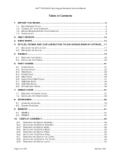
DellTM XFR D630 Fully Rugged Notebook Service Manual Table of Contents 1 BEFORE YOU BEGIN ...6 1.1 RECOMMENDED TOOLS ...6 1.2 TURNING OFF YOUR COMPUTER 6 1.3 BEFORE WORKING INSIDE YOUR COMPUTER 6 1.4 SCREW CHART ...8 2 XBAY DEVICES ...13 3 HARD DRIVE...14 4 ...
DellTM XFR D630 Fully Rugged Notebook Service Manual Table of Contents 1 BEFORE YOU BEGIN ...6 1.1 RECOMMENDED TOOLS ...6 1.2 TURNING OFF YOUR COMPUTER 6 1.3 BEFORE WORKING INSIDE YOUR COMPUTER 6 1.4 SCREW CHART ...8 2 XBAY DEVICES ...13 3 HARD DRIVE...14 4 ...

Service Manual
Page 4
DellTM XFR D630 Fully Rugged Notebook Service Manual 10.10 INSTALLING THE DISPLAY LATCH 68 11 INTERNAL CARD WITH BLUETOOTH® WIRELESS TECHNOLOGY 68 11.1 REMOVING THE BLUETOOTH® WIRELESS CARD 68 11.2 ...
DellTM XFR D630 Fully Rugged Notebook Service Manual 10.10 INSTALLING THE DISPLAY LATCH 68 11 INTERNAL CARD WITH BLUETOOTH® WIRELESS TECHNOLOGY 68 11.1 REMOVING THE BLUETOOTH® WIRELESS CARD 68 11.2 ...

Service Manual
Page 5
DellTM XFR D630 Fully Rugged Notebook Service Manual 24 RF PASSTHRU BOARD 102 24.1 REMOVING THE RF PASSTHRU BOARD 102 24.2 INSTALLING THE RF PASSTHRU BOARD 103 25 BOTTOM CHASSIS 104 25.1 25.2 25.3 25.4 REMOVING THE BOTTOM CHASSIS 104 INSTALLING THE BOTTOM CHASSIS 105 REMOVING THE MODEM CABLE 105 INSTALLING THE MODEM CABLE 105 Page 5 of 106 Revision A01
DellTM XFR D630 Fully Rugged Notebook Service Manual 24 RF PASSTHRU BOARD 102 24.1 REMOVING THE RF PASSTHRU BOARD 102 24.2 INSTALLING THE RF PASSTHRU BOARD 103 25 BOTTOM CHASSIS 104 25.1 25.2 25.3 25.4 REMOVING THE BOTTOM CHASSIS 104 INSTALLING THE BOTTOM CHASSIS 105 REMOVING THE MODEM CABLE 105 INSTALLING THE MODEM CABLE 105 Page 5 of 106 Revision A01

Service Manual
Page 6
...computer. Hold a card by its edges or by your computer. 1. Unless otherwise noted, each procedure assumes that is not authorized by Dell is not covered by its pins. If your computer and attached devices do not automatically turn off . Shut down . Hold a component...open files and exit any attached devices are turned off your warranty. CAUTION: Handle components and cards with care. DellTM XFR D630 Fully Rugged Notebook Service Manual 1 Before You Begin This chapter provides procedures for 4 seconds. 1.3 Before Working Inside Your Computer Use the following tools:...
...computer. Hold a card by its edges or by your computer. 1. Unless otherwise noted, each procedure assumes that is not authorized by Dell is not covered by its pins. If your computer and attached devices do not automatically turn off . Shut down . Hold a component...open files and exit any attached devices are turned off your warranty. CAUTION: Handle components and cards with care. DellTM XFR D630 Fully Rugged Notebook Service Manual 1 Before You Begin This chapter provides procedures for 4 seconds. 1.3 Before Working Inside Your Computer Use the following tools:...
Service Manual
Page 7
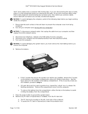
... USB cables from the computer. 4. a. b. NOTICE: To avoid damaging the computer, perform the following steps before you begin working inside the computer. 1. DellTM XFR D630 Fully Rugged Notebook Service Manual itself. Some cables have a connector with locking tabs; NOTICE: To avoid damaging the system board, you must remove the main battery before you...
... USB cables from the computer. 4. a. b. NOTICE: To avoid damaging the computer, perform the following steps before you begin working inside the computer. 1. DellTM XFR D630 Fully Rugged Notebook Service Manual itself. Some cables have a connector with locking tabs; NOTICE: To avoid damaging the system board, you must remove the main battery before you...
Service Manual
Page 8
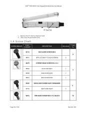
Remove the PC Card or Express Card. d. DellTM XFR D630 Fully Rugged Notebook Service Manual PC Card Slot c. Then close the protective door. 1.4 Screw Chart SCREW IMAGE PART NUMBER DESCRIPTION 18114 SHOULDER SCREW M2.5 18815 XFR LCD ASSY TOUCH SCREEN Qty/Assy Total Qty 6 6 18279 CHEESE HEAD SCREW M1.2 X 3 18806 18808 18812 AV DOOR ASSY VGA DOOR ASSY DVD DOOR ASSY 1 3 1 1 18353 SHOULDER SCREW-HEAT SPREADER 3 18035 HEAT SINK ASSY 3 18415 PAN HEAD SCREW M2.5 X 8 -BLACK 19 Page 8 of 106 Revision A01
Remove the PC Card or Express Card. d. DellTM XFR D630 Fully Rugged Notebook Service Manual PC Card Slot c. Then close the protective door. 1.4 Screw Chart SCREW IMAGE PART NUMBER DESCRIPTION 18114 SHOULDER SCREW M2.5 18815 XFR LCD ASSY TOUCH SCREEN Qty/Assy Total Qty 6 6 18279 CHEESE HEAD SCREW M1.2 X 3 18806 18808 18812 AV DOOR ASSY VGA DOOR ASSY DVD DOOR ASSY 1 3 1 1 18353 SHOULDER SCREW-HEAT SPREADER 3 18035 HEAT SINK ASSY 3 18415 PAN HEAD SCREW M2.5 X 8 -BLACK 19 Page 8 of 106 Revision A01

Service Manual
Page 9
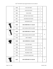
DellTM XFR D630 Fully Rugged Notebook Service Manual 18815 XFR LCD ASSY TOUCH SCREEN 4 18802 PALMREST ASSY 11 18043 ASSY HANDLE WITH HOLDER 2 18619 LCD LATCH ASSY 2 18416 18044 18824 SCR,M3X14,PHH,MSCR,ZPS,XFR ASSY HANDLE SHOULDER STRAP ASSY 8 6 2 18417 PAN HEAD SCREW M2 X 12 -BLACK 7 18815 XFR LCD ASSY TOUCH SCREEN 7 18419 PAN HEAD...
DellTM XFR D630 Fully Rugged Notebook Service Manual 18815 XFR LCD ASSY TOUCH SCREEN 4 18802 PALMREST ASSY 11 18043 ASSY HANDLE WITH HOLDER 2 18619 LCD LATCH ASSY 2 18416 18044 18824 SCR,M3X14,PHH,MSCR,ZPS,XFR ASSY HANDLE SHOULDER STRAP ASSY 8 6 2 18417 PAN HEAD SCREW M2 X 12 -BLACK 7 18815 XFR LCD ASSY TOUCH SCREEN 7 18419 PAN HEAD...
Service Manual
Page 10
DellTM XFR D630 Fully Rugged Notebook Service Manual 18806 18810 18804 18807 18811 18623 18424 18043 18425 18043 18044 18426 18806 18808 18812 18802 18618 AV DOOR ASSY HDD DOOR ASSY FAN COVER BATTERY DOOR ASSY DOCKING DOOR ASSY KEYBOARD ASSY CSK SCREW M3 X 10 -BLACK ASSY HANDLE WITH HOLDER CSK SCREW M2 X 10 -BLACK ASSY HANDLE WITH HOLDER ASSY HANDLE CSK SCREW M2 X 3 -BLACK AV DOOR ASSY VGA DOOR ASSY DVD DOOR ASSY PALMREST ASSY AV DOOR COVER ASSY 4 2 4 2 6 4 4 4 4 2 2 2 2 10 2 2 2 18427 CSK SCREW M2.5 X 6 -BLACK 3 Page 10 of 106 Revision A01
DellTM XFR D630 Fully Rugged Notebook Service Manual 18806 18810 18804 18807 18811 18623 18424 18043 18425 18043 18044 18426 18806 18808 18812 18802 18618 AV DOOR ASSY HDD DOOR ASSY FAN COVER BATTERY DOOR ASSY DOCKING DOOR ASSY KEYBOARD ASSY CSK SCREW M3 X 10 -BLACK ASSY HANDLE WITH HOLDER CSK SCREW M2 X 10 -BLACK ASSY HANDLE WITH HOLDER ASSY HANDLE CSK SCREW M2 X 3 -BLACK AV DOOR ASSY VGA DOOR ASSY DVD DOOR ASSY PALMREST ASSY AV DOOR COVER ASSY 4 2 4 2 6 4 4 4 4 2 2 2 2 10 2 2 2 18427 CSK SCREW M2.5 X 6 -BLACK 3 Page 10 of 106 Revision A01
Service Manual
Page 11
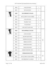
DellTM XFR D630 Fully Rugged Notebook Service Manual 18808 18812 18428 18815 18808 18802 18813 18814 18429 18810 18807 18630 18809 18631 18632 18628 18444 18815 18803 VGA DOOR ASSY DVD DOOR ASSY CSK SCREW M2 X 8 -BLACK XFR LCD ASSY TOUCH SCREEN VGA DOOR ASSY PALMREST ASSY RJ DOOR ASSY USB PLASTIC DOOR ASSY CSK SCREW M2 X 6 -BLACK HDD DOOR ASSY BATTERY DOOR ASSY USB SIDE DOOR ASSY DIMMS DOOR ASSY POWER DOOR ASSY PCMCIA DOOR ASSY RUBBER KEYBOARD ASSY SCR,M2.5X5,PHH,TF,BCS XFR LCD ASSY TOUCH SCREEN MOTHERBOARD TO CHASSIS 1 2 2 2 10 2 2 2 2 2 2 30 4 2 3 15 10 6 4 Page 11 of 106 Revision A01
DellTM XFR D630 Fully Rugged Notebook Service Manual 18808 18812 18428 18815 18808 18802 18813 18814 18429 18810 18807 18630 18809 18631 18632 18628 18444 18815 18803 VGA DOOR ASSY DVD DOOR ASSY CSK SCREW M2 X 8 -BLACK XFR LCD ASSY TOUCH SCREEN VGA DOOR ASSY PALMREST ASSY RJ DOOR ASSY USB PLASTIC DOOR ASSY CSK SCREW M2 X 6 -BLACK HDD DOOR ASSY BATTERY DOOR ASSY USB SIDE DOOR ASSY DIMMS DOOR ASSY POWER DOOR ASSY PCMCIA DOOR ASSY RUBBER KEYBOARD ASSY SCR,M2.5X5,PHH,TF,BCS XFR LCD ASSY TOUCH SCREEN MOTHERBOARD TO CHASSIS 1 2 2 2 10 2 2 2 2 2 2 30 4 2 3 15 10 6 4 Page 11 of 106 Revision A01

Service Manual
Page 12
DellTM XFR D630 Fully Rugged Notebook Service Manual 18451 18802 18477 18802 18043 18803 18819 18517 18044 18535 18623 18816 18539 18629 18550 18824 PAN HEAD SCREW M2 X 8-BLACK PALMREST ASSY PANHEAD SCREW M2X4 PALMREST ASSY ASSY HANDLE WITH HOLDER RF PASS THROUGH LCD TOP COVER ASSY SCR,M3X6,PHH,MSCR,ZPS,XFR ASSY HANDLE CSK CAPTIVE SCREW M2 X 6 KEYBOARD ASSY HINGE COVER ASSY PAN HEAD SCREW M3 X 14 -BLACK STYLUS KIT ASSY PAN HEAD SCREW M3 X 22 -BLACK SHOULDER STRAP ASSY 1 1 1 9 4 2 2 2 2 19 15 4 1 1 2 2 18590 SCREW,KYBD BLK, PAN HEAD M2X3 19 Page 12 of 106 Revision A01
DellTM XFR D630 Fully Rugged Notebook Service Manual 18451 18802 18477 18802 18043 18803 18819 18517 18044 18535 18623 18816 18539 18629 18550 18824 PAN HEAD SCREW M2 X 8-BLACK PALMREST ASSY PANHEAD SCREW M2X4 PALMREST ASSY ASSY HANDLE WITH HOLDER RF PASS THROUGH LCD TOP COVER ASSY SCR,M3X6,PHH,MSCR,ZPS,XFR ASSY HANDLE CSK CAPTIVE SCREW M2 X 6 KEYBOARD ASSY HINGE COVER ASSY PAN HEAD SCREW M3 X 14 -BLACK STYLUS KIT ASSY PAN HEAD SCREW M3 X 22 -BLACK SHOULDER STRAP ASSY 1 1 1 9 4 2 2 2 2 19 15 4 1 1 2 2 18590 SCREW,KYBD BLK, PAN HEAD M2X3 19 Page 12 of 106 Revision A01

Service Manual
Page 13
... when they are not installed in the computer. If present, remove the device locking screw from the bottom of 106 Revision A01 DellTM XFR D630 Fully Rugged Notebook Service Manual 18815 XFR LCD ASSY TOUCH SCREEN 8 18802 PALMREST ASSY 2 18803 CARD CAGE ON BASE CHASSIS 4 18623 KEYBOARD ASSY 3 18823 MOTHERBOARD ASSY 2 18591 18802 PAN...
... when they are not installed in the computer. If present, remove the device locking screw from the bottom of 106 Revision A01 DellTM XFR D630 Fully Rugged Notebook Service Manual 18815 XFR LCD ASSY TOUCH SCREEN 8 18802 PALMREST ASSY 2 18803 CARD CAGE ON BASE CHASSIS 4 18623 KEYBOARD ASSY 3 18823 MOTHERBOARD ASSY 2 18591 18802 PAN...

Service Manual
Page 14
.... You also need the Operating System media to install the drivers and utilities on , in standby mode, or in the XFR D630 User's Guide. NOTE: Dell does not guarantee compatibility or provide support for your computer to install the Microsoft® Windows® operating system. To install...computer over and locate the hard disk drive compartment using the figure below. Pull the device out of 106 Revision A01 DellTM XFR D630 Fully Rugged Notebook Service Manual 1 Optical drive 2 Device Latch release 4. even a slight bump can damage the drive. Page 14 of the XBay. ...
.... You also need the Operating System media to install the drivers and utilities on , in standby mode, or in the XFR D630 User's Guide. NOTE: Dell does not guarantee compatibility or provide support for your computer to install the Microsoft® Windows® operating system. To install...computer over and locate the hard disk drive compartment using the figure below. Pull the device out of 106 Revision A01 DellTM XFR D630 Fully Rugged Notebook Service Manual 1 Optical drive 2 Device Latch release 4. even a slight bump can damage the drive. Page 14 of the XBay. ...

Service Manual
Page 15
Page 15 of 106 Revision A01 If the 2 security screws are installed, remove the 2 screws on the latches on the hard disk drive compartment using a #1 Philips screw driver. If the 2 optional screws that secure the quarter-turn , towards the 'unlock' icon, to step 4. 4. Lift each latch, and turn each a quarter-turn latches are not installed, proceed to release the latching mechanism. DellTM XFR D630 Fully Rugged Notebook Service Manual 3.
Page 15 of 106 Revision A01 If the 2 security screws are installed, remove the 2 screws on the latches on the hard disk drive compartment using a #1 Philips screw driver. If the 2 optional screws that secure the quarter-turn , towards the 'unlock' icon, to step 4. 4. Lift each latch, and turn each a quarter-turn latches are not installed, proceed to release the latching mechanism. DellTM XFR D630 Fully Rugged Notebook Service Manual 3.

Service Manual
Page 16
... in protective antistatic packaging. 8. Locate the tab on the hard disk drive and pull it in removing the hard disk drive from the motherboard. 7. DellTM XFR D630 Fully Rugged Notebook Service Manual 5.
... in protective antistatic packaging. 8. Locate the tab on the hard disk drive and pull it in removing the hard disk drive from the motherboard. 7. DellTM XFR D630 Fully Rugged Notebook Service Manual 5.

Service Manual
Page 17
...The stylus clip can be equipped with the optional stylus housing, stylus, stylus tether, and stylus clip. If your computer (see the XFR D630 User's Guide for information). 4 Stylus, Tether and Clip (DirectVue Touch Screen Display option) NOTE: Only Touch Screen Display configurations will... include the stylus, stylus housing, tether and stylus clip. DellTM XFR D630 Fully Rugged Notebook Service Manual 9. To replace the stylus, stylus tether or stylus clip, follow the directions provided in the sections below. 1 Stylus ...
...The stylus clip can be equipped with the optional stylus housing, stylus, stylus tether, and stylus clip. If your computer (see the XFR D630 User's Guide for information). 4 Stylus, Tether and Clip (DirectVue Touch Screen Display option) NOTE: Only Touch Screen Display configurations will... include the stylus, stylus housing, tether and stylus clip. DellTM XFR D630 Fully Rugged Notebook Service Manual 9. To replace the stylus, stylus tether or stylus clip, follow the directions provided in the sections below. 1 Stylus ...
Service Manual
Page 18
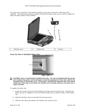
To replace the stylus clip: 1. DellTM XFR D630 Fully Rugged Notebook Service Manual The stylus clip is installed on the handle assembly's end screw on the left -handed use. 2. Loosen the screw on the end of Installed Stylus ...
To replace the stylus clip: 1. DellTM XFR D630 Fully Rugged Notebook Service Manual The stylus clip is installed on the handle assembly's end screw on the left -handed use. 2. Loosen the screw on the end of Installed Stylus ...

Service Manual
Page 19
...provides instructions for right or left or right side of the handle to tighten the screw that was loosened in step 1. DellTM XFR D630 Fully Rugged Notebook Service Manual 4. Pull the stylus and tether through the loop. b. b. Place one side of the tether through the loop until the...replace the stylus: 1. Remove the stylus from the stylus clip: a. Pull the stylus and tether through the loop until tight. 5 Handle The XFR D630 is required. Install the new stylus: a. c. Place the free end of 106 Revision A01 Pull the stylus and tether through the stylus clip....
...provides instructions for right or left or right side of the handle to tighten the screw that was loosened in step 1. DellTM XFR D630 Fully Rugged Notebook Service Manual 4. Pull the stylus and tether through the loop. b. b. Place one side of the tether through the loop until the...replace the stylus: 1. Remove the stylus from the stylus clip: a. Pull the stylus and tether through the loop until tight. 5 Handle The XFR D630 is required. Install the new stylus: a. c. Place the free end of 106 Revision A01 Pull the stylus and tether through the stylus clip....

Service Manual
Page 20
... shown in the figure above . 2. Remove the 6 screws (3 on each side) on the top of 106 Revision A01 DellTM XFR D630 Fully Rugged Notebook Service Manual 1 Main handle assembly 2 Handle cover (2) 5.1 Removing the Handle 1. Secure the main handle assembly to the handle brackets. Remove... the 6 screws (3 on each handle cover) that secure the handle to the XFR D630 using the 6 screws provided. 3. Page 20 ...
... shown in the figure above . 2. Remove the 6 screws (3 on each side) on the top of 106 Revision A01 DellTM XFR D630 Fully Rugged Notebook Service Manual 1 Main handle assembly 2 Handle cover (2) 5.1 Removing the Handle 1. Secure the main handle assembly to the handle brackets. Remove... the 6 screws (3 on each handle cover) that secure the handle to the XFR D630 using the 6 screws provided. 3. Page 20 ...

Service Manual
Page 21
Remove the 2 screws that secure the Comms Door. 2. Remove the Comms Door from the notebook. DellTM XFR D630 Fully Rugged Notebook Service Manual 4. Align each side). 6 Port Covers The XFR D630 utilizes port covers to Replacing the 97H Stylus Clip for instructions regarding installing the stylus clip onto one side of 106 Revision A01 Secure the...
Remove the 2 screws that secure the Comms Door. 2. Remove the Comms Door from the notebook. DellTM XFR D630 Fully Rugged Notebook Service Manual 4. Align each side). 6 Port Covers The XFR D630 utilizes port covers to Replacing the 97H Stylus Clip for instructions regarding installing the stylus clip onto one side of 106 Revision A01 Secure the...


