Technical Guide
Page 4
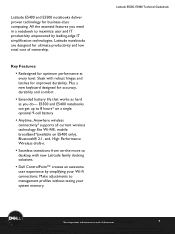
Sleek with new Latitude family docking solutions. ƒ Dell ControlPoint™ creates an awesome user experience by leading-edge IT simplification technologies. Latitude E5400 and E5500 notebooks deliver proven technology for accuracy, durability and comfort . ƒ Extended battery life... profiles without taxing your Wi-Fi connections. Make adjustments to desktop with robust hinges and latches for optimum performance at end of ownership. LatitudeLaLEta-itFtuiatdmuedileEy5EM550a5i00n,0sEt,r5Ee45a04m000TeTcehcnhincaiclaGl Guiudiedbeobookok *See important information at every level....
Sleek with new Latitude family docking solutions. ƒ Dell ControlPoint™ creates an awesome user experience by leading-edge IT simplification technologies. Latitude E5400 and E5500 notebooks deliver proven technology for accuracy, durability and comfort . ƒ Extended battery life... profiles without taxing your Wi-Fi connections. Make adjustments to desktop with robust hinges and latches for optimum performance at end of ownership. LatitudeLaLEta-itFtuiatdmuedileEy5EM550a5i00n,0sEt,r5Ee45a04m000TeTcehcnhincaiclaGl Guiudiedbeobookok *See important information at every level....
Technical Guide
Page 15
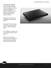
... means E-Family is designed for everyday computing. Sleek, Durable Design Latitude E5500 and E5400 have been designed to deliver proven technologies for improved keycap retention and screen printing on keys. Our 7200rpm hard drives now come standard with redesigned robust hinges & latches. Latitude E5500L,aEti5tu4d0e0 EM5a5i0n0st,rEe5a4m00TeTcehcnhinciaclaGl Guiudiedbeobookok *See important information at end of...
... means E-Family is designed for everyday computing. Sleek, Durable Design Latitude E5500 and E5400 have been designed to deliver proven technologies for improved keycap retention and screen printing on keys. Our 7200rpm hard drives now come standard with redesigned robust hinges & latches. Latitude E5500L,aEti5tu4d0e0 EM5a5i0n0st,rEe5a4m00TeTcehcnhinciaclaGl Guiudiedbeobookok *See important information at end of...
Service Manual
Page 1
...or other countries; Dell™ Latitude™ E5400 and E5500 Service Manual Troubleshooting Working on Your Computer Bottom of the Base Assembly Hard Drive Wireless Local Area Network (WLAN) Card Modem Card Fan Processor Heat Sink Processor Module Memory Hinge Cover Keyboard LED ...Dell under license; If you how to change without the written permission of Intel Corporation in this text: Dell, Latitude, ExpressCharge, and the DELL logo are not applicable. and other countries. is used in any references in the U.S. Intel and Celeron are registered trademarks, and Core...
...or other countries; Dell™ Latitude™ E5400 and E5500 Service Manual Troubleshooting Working on Your Computer Bottom of the Base Assembly Hard Drive Wireless Local Area Network (WLAN) Card Modem Card Fan Processor Heat Sink Processor Module Memory Hinge Cover Keyboard LED ...Dell under license; If you how to change without the written permission of Intel Corporation in this text: Dell, Latitude, ExpressCharge, and the DELL logo are not applicable. and other countries. is used in any references in the U.S. Intel and Celeron are registered trademarks, and Core...
Service Manual
Page 14
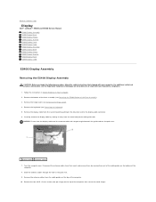
... on the blue tab next to Contents Page Display Dell™ Latitude™ E5400 and E5500 Service Manual E5400 Display Assembly E5400 Display Bezel E5400 Display Hinges E5400 Display Inverter E5400 Display Panel E5400 Display Cable E5500 Display Assembly E5500 Display Bezel E5500 Display Hinges E5500 Display Inverter E5500 Display Panel E5500 Display Cable E5400 Display Assembly Removing the E5400 Display...
... on the blue tab next to Contents Page Display Dell™ Latitude™ E5400 and E5500 Service Manual E5400 Display Assembly E5400 Display Bezel E5400 Display Hinges E5400 Display Inverter E5400 Display Panel E5400 Display Cable E5500 Display Assembly E5500 Display Bezel E5500 Display Hinges E5500 Display Inverter E5500 Display Panel E5500 Display Cable E5400 Display Assembly Removing the E5400 Display...
Service Manual
Page 33
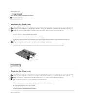
... cover with your computer. Follow the procedures in Before Working on Your Computer. 2. Back to Contents Page Hinge Cover Dell™ Latitude™ E5400 and E5500 Service Manual Removing the Hinge Cover Replacing the Hinge Cover Removing the Hinge Cover CAUTION: Before you begin any of the procedures in this section, follow the safety instructions that shipped...
... cover with your computer. Follow the procedures in Before Working on Your Computer. 2. Back to Contents Page Hinge Cover Dell™ Latitude™ E5400 and E5500 Service Manual Removing the Hinge Cover Replacing the Hinge Cover Removing the Hinge Cover CAUTION: Before you begin any of the procedures in this section, follow the safety instructions that shipped...
Service Manual
Page 34
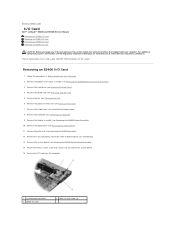
... DC-in this section, follow the safety instructions that secures the I/O card to the system board. 15. Remove the fan (see Removing the Hinge Cover). 8. Remove the coin cell battery connector (refer to Removing the Coin-Cell Battery). 13. The I /O card 2 M2.5 x 5-... Remove the optical drive (see Removing the Keyboard). 9. Back to Contents Page I/O Card Dell™ Latitude™ E5400 and E5500 Service Manual Removing an E5400 I/O Card Replacing an E5400 I/O Card Removing an E5500 I/O Card Replacing an E5500 I/O Card CAUTION: Before you begin any of the Base Assembly). 3.
... DC-in this section, follow the safety instructions that secures the I/O card to the system board. 15. Remove the fan (see Removing the Hinge Cover). 8. Remove the coin cell battery connector (refer to Removing the Coin-Cell Battery). 13. The I /O card 2 M2.5 x 5-... Remove the optical drive (see Removing the Keyboard). 9. Back to Contents Page I/O Card Dell™ Latitude™ E5400 and E5500 Service Manual Removing an E5400 I/O Card Replacing an E5400 I/O Card Removing an E5500 I/O Card Replacing an E5500 I/O Card CAUTION: Before you begin any of the Base Assembly). 3.
Service Manual
Page 37
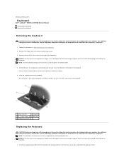
... information, see Removing the Hinge Cover). 3. Gently rock the keyboard back and forth while pulling it toward the display. 5. Remove the two M2 x 3-mm screws at the top of the keyboard. Slide the keyboard out of the keyboard. Back to Contents Page Keyboard Dell™ Latitude™ E5400 and E5500 Service Manual Removing the...
... information, see Removing the Hinge Cover). 3. Gently rock the keyboard back and forth while pulling it toward the display. 5. Remove the two M2 x 3-mm screws at the top of the keyboard. Slide the keyboard out of the keyboard. Back to Contents Page Keyboard Dell™ Latitude™ E5400 and E5500 Service Manual Removing the...
Service Manual
Page 39
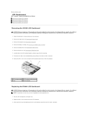
Back to Contents Page LED Dashboard Dell™ Latitude™ E5400 and E5500 Service Manual Removing the E5400 LED Dashboard Replacing the E5400 LED Dashboard Removing the E5500 LED Dashboard Replacing the E5500 LED Dashboard Removing the E5400 LED Dashboard CAUTION: Before you begin any of the procedures ... the cable's connector. For additional safety best practices information, see Removing the E5400 Display Assembly). 5. Remove the hinge cover (see Removing the Hinge Cover). 3. Gently connect the LED Dashboard cable to the motherboard by sliding it from the metal tab. 8.
Back to Contents Page LED Dashboard Dell™ Latitude™ E5400 and E5500 Service Manual Removing the E5400 LED Dashboard Replacing the E5400 LED Dashboard Removing the E5500 LED Dashboard Replacing the E5500 LED Dashboard Removing the E5400 LED Dashboard CAUTION: Before you begin any of the procedures ... the cable's connector. For additional safety best practices information, see Removing the E5400 Display Assembly). 5. Remove the hinge cover (see Removing the Hinge Cover). 3. Gently connect the LED Dashboard cable to the motherboard by sliding it from the metal tab. 8.

Service Manual
Page 48
Back to Contents Page Palm Rest Dell™ Latitude™ E5400 and E5500 Service Manual Removing the E5400 Palm Rest Replacing the E5400 Palm Rest Removing the E5500 Palm Rest Replacing the E5500 Palm Rest Removing the E5400 Palm Rest CAUTION: Before you begin the following procedure, follow... The screw locations may vary slightly on the top of the Base Assembly). 3. Remove the hinge cover (see Removing the E5400 Display Assembly). 8. Remove the display assembly (see Removing the Hinge Cover). 6. Remove the bottom of the base assembly (see the Regulatory Compliance Homepage on Your ...
Back to Contents Page Palm Rest Dell™ Latitude™ E5400 and E5500 Service Manual Removing the E5400 Palm Rest Replacing the E5400 Palm Rest Removing the E5500 Palm Rest Replacing the E5500 Palm Rest Removing the E5400 Palm Rest CAUTION: Before you begin the following procedure, follow... The screw locations may vary slightly on the top of the Base Assembly). 3. Remove the hinge cover (see Removing the E5400 Display Assembly). 8. Remove the display assembly (see Removing the Hinge Cover). 6. Remove the bottom of the base assembly (see the Regulatory Compliance Homepage on Your ...
Service Manual
Page 53
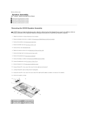
...the four M2 x 3-mm screws that secure each of the base assembly (see Removing the E5400 Palm Rest). 12. Remove the hinge cover (see Removing the Optical Drive). 11. Remove the display assembly (see the Regulatory Compliance Homepage on Your Computer. 2. For... assembly. 1 left speaker assemblies to Contents Page Speaker Assembly Dell™ Latitude™ E5400 and E5500 Service Manual Removing the E5400 Speaker Assembly Replacing the E5400 Speaker Assembly Removing the E5500 Speaker Assembly Replacing the E5500 Speaker Assembly Removing the E5400 Speaker Assembly CAUTION: Before you ...
...the four M2 x 3-mm screws that secure each of the base assembly (see Removing the E5400 Palm Rest). 12. Remove the hinge cover (see Removing the Optical Drive). 11. Remove the display assembly (see the Regulatory Compliance Homepage on Your Computer. 2. For... assembly. 1 left speaker assemblies to Contents Page Speaker Assembly Dell™ Latitude™ E5400 and E5500 Service Manual Removing the E5400 Speaker Assembly Replacing the E5400 Speaker Assembly Removing the E5500 Speaker Assembly Replacing the E5500 Speaker Assembly Removing the E5400 Speaker Assembly CAUTION: Before you ...
Service Manual
Page 57
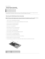
...(see Removing the E5400 Palm Rest). 12. Follow the instructions in Before Working on www.dell.com at: www.dell.com/regulatory_compliance. 1. Remove the palm rest (see Removing the Hinge Cover). 8. Lift the left edge of the system board off of the I/O board connector,...the Service Tag to Contents Page System Board Assembly Dell™ Latitude™ E5400 and E5500 Service Manual Removing the E5400 System Board Assembly Replacing the E5400 System Board Assembly Removing the E5500 System Board Assembly Replacing the E5500 System Board Assembly The system board's BIOS chip ...
...(see Removing the E5400 Palm Rest). 12. Follow the instructions in Before Working on www.dell.com at: www.dell.com/regulatory_compliance. 1. Remove the palm rest (see Removing the Hinge Cover). 8. Lift the left edge of the system board off of the I/O board connector,...the Service Tag to Contents Page System Board Assembly Dell™ Latitude™ E5400 and E5500 Service Manual Removing the E5400 System Board Assembly Replacing the E5400 System Board Assembly Removing the E5500 System Board Assembly Replacing the E5500 System Board Assembly The system board's BIOS chip ...


