Quick Reference Guide
Page 28
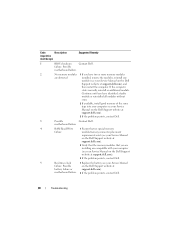
...computer (see your Service Manual on the Dell Support website at support.dell.com). 3 If the problem persists, contact Dell. 3 Possible Contact Dell. Possible motherboard failure. 2 No memory ...dell.com). 2 Verify that the memory modules that no special memory failure module/memory connector placement requirements exist (see your Service Manual on the Dell Support website at battery failure or support.dell.com). If the computer starts normally, reinstall an additional module. Code Description (repetitive short beeps) Suggested Remedy 1 BIOS checksum Contact Dell...
...computer (see your Service Manual on the Dell Support website at support.dell.com). 3 If the problem persists, contact Dell. 3 Possible Contact Dell. Possible motherboard failure. 2 No memory ...dell.com). 2 Verify that the memory modules that no special memory failure module/memory connector placement requirements exist (see your Service Manual on the Dell Support website at battery failure or support.dell.com). If the computer starts normally, reinstall an additional module. Code Description (repetitive short beeps) Suggested Remedy 1 BIOS checksum Contact Dell...
Quick Reference Guide
Page 29
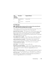
... A C H E D I S A B L E D D U E T O F A I L E D INITIALIZATION - The primary cache internal to commands from the computer. Contact Dell (see "Dell Diagnostics" on page 61). DRIVE NOT READY - The operation requires a hard drive in the system setup program. Troubleshooting 29 Enable the Pointing Device option in... Dell (see the documentation for more information. Contact Dell. C D D R I V E C O N T R O L L E R F A I L A B L E M E M O R Y - Code Description (repetitive short beeps) 6 Video BIOS Test Failure 7 CPU cache test failure Suggested Remedy Contact Dell....
... A C H E D I S A B L E D D U E T O F A I L E D INITIALIZATION - The primary cache internal to commands from the computer. Contact Dell (see "Dell Diagnostics" on page 61). DRIVE NOT READY - The operation requires a hard drive in the system setup program. Troubleshooting 29 Enable the Pointing Device option in... Dell (see the documentation for more information. Contact Dell. C D D R I V E C O N T R O L L E R F A I L A B L E M E M O R Y - Code Description (repetitive short beeps) 6 Video BIOS Test Failure 7 CPU cache test failure Suggested Remedy Contact Dell....
Quick Reference Guide
Page 35
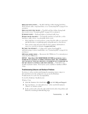
...: Windows Vista: 1 Click the Windows Vista Start button , and click Help and Support. 2 Type hardware troubleshooter in BIOS setup. KEYBOARD FAILURE - USB OVER CURRENT ERROR - HA R D -DISK DRIVE FAILURE - No bootable partition on page... OPERATING RANGE. HA R D -D I S K D R I V E R E A D F A I N T E R R U P T - Disconnect the USB device. S.M.A.R.T error, possible hard drive failure. DELL RECOMMENDS THAT YOU BACK UP YOUR DATA REGULARLY. Troubleshooting 35 NOTICE - Keyboard failure or keyboard cable loose. N O T I M E R T I C K I L U R E - A chip on page 61 for the...
...: Windows Vista: 1 Click the Windows Vista Start button , and click Help and Support. 2 Type hardware troubleshooter in BIOS setup. KEYBOARD FAILURE - USB OVER CURRENT ERROR - HA R D -DISK DRIVE FAILURE - No bootable partition on page... OPERATING RANGE. HA R D -D I S K D R I V E R E A D F A I N T E R R U P T - Disconnect the USB device. S.M.A.R.T error, possible hard drive failure. DELL RECOMMENDS THAT YOU BACK UP YOUR DATA REGULARLY. Troubleshooting 35 NOTICE - Keyboard failure or keyboard cable loose. N O T I M E R T I C K I L U R E - A chip on page 61 for the...
Technical Guide
Page 63
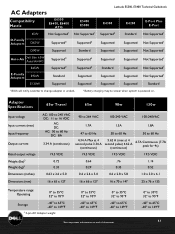
...D65W Supported2 D90W Supported E5400 E5500 Not Supported1 Supported2 Standard Latitude E5500, E5400 Technical Guidebook E4300 Supported2 Supported Supported E4200 E-Port Plus E-Port Standard Not Supported1 Supported Supported Not Supported1 Not Supported1 Auto-Air Dell Slim 65W Auto/Air/AC... E-Family Adapters E65W E90W E130W Supported2 Supported2 Standard Supported Supported2 Supported2 Supported Supported Supported Standard Supported Supported Supported Not Supported1 Supported Supported Not Supported1 Not Supported1 Supported Standard 1 BIOS ...
...D65W Supported2 D90W Supported E5400 E5500 Not Supported1 Supported2 Standard Latitude E5500, E5400 Technical Guidebook E4300 Supported2 Supported Supported E4200 E-Port Plus E-Port Standard Not Supported1 Supported Supported Not Supported1 Not Supported1 Auto-Air Dell Slim 65W Auto/Air/AC... E-Family Adapters E65W E90W E130W Supported2 Supported2 Standard Supported Supported2 Supported2 Supported Supported Supported Standard Supported Supported Supported Not Supported1 Supported Supported Not Supported1 Not Supported1 Supported Standard 1 BIOS ...
Service Manual
Page 1
... Core is strictly forbidden. Intel and Celeron are either trademarks or registered trademarks of Microsoft Corporation in this document to change without the written permission of Dell...either the entities claiming the marks and names or their products. Dell™ Latitude™ E5400 and E5500 Service Manual Troubleshooting Working on Your Computer Bottom of the Base Assembly... the BIOS Notes, Notices, and Cautions NOTE: A NOTE indicates important information that helps you purchased a DELL™ n Series computer, any manner whatsoever without notice. © 2008 Dell Inc....
... Core is strictly forbidden. Intel and Celeron are either trademarks or registered trademarks of Microsoft Corporation in this document to change without the written permission of Dell...either the entities claiming the marks and names or their products. Dell™ Latitude™ E5400 and E5500 Service Manual Troubleshooting Working on Your Computer Bottom of the Base Assembly... the BIOS Notes, Notices, and Cautions NOTE: A NOTE indicates important information that helps you purchased a DELL™ n Series computer, any manner whatsoever without notice. © 2008 Dell Inc....
Service Manual
Page 4
...management mode. If you service the computer. 5. Back to Contents Page Working on Your Computer Dell™ Latitude™ E5400 and E5500 Service Manual Recommended Tools Before Working on Your Computer After Working on Your Computer This document provides...BIOS update (see the Regulatory Compliance Homepage on a card. l In Microsoft Windows Vista®, click Start , click the arrow icon, and then click Shut Down to prevent the computer cover from their electrical outlets. For additional safety best practices information, see the Dell Support website at support.dell...
...management mode. If you service the computer. 5. Back to Contents Page Working on Your Computer Dell™ Latitude™ E5400 and E5500 Service Manual Recommended Tools Before Working on Your Computer After Working on Your Computer This document provides...BIOS update (see the Regulatory Compliance Homepage on a card. l In Microsoft Windows Vista®, click Start , click the arrow icon, and then click Shut Down to prevent the computer cover from their electrical outlets. For additional safety best practices information, see the Dell Support website at support.dell...
Service Manual
Page 6
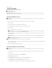
... shut down arrow to view the Save In menu, select Desktop, and then click Save. Back to Contents Page Flashing the BIOS Dell™ Latitude™ E5400 and E5500 Service Manual Flashing the BIOS From a CD Flashing the BIOS From the Hard Drive If a BIOS-update program media, such as a CD, is complete, the computer automatically reboots. 9.
... shut down arrow to view the Save In menu, select Desktop, and then click Save. Back to Contents Page Flashing the BIOS Dell™ Latitude™ E5400 and E5500 Service Manual Flashing the BIOS From a CD Flashing the BIOS From the Hard Drive If a BIOS-update program media, such as a CD, is complete, the computer automatically reboots. 9.

Service Manual
Page 7
Double-click the file icon on the desktop and follow the instructions on your desktop. 8. Back to your desktop and is titled the same as the downloaded BIOS update file. 9. The file downloads to Contents Page The file icon appears on the screen. Click Close if the Download Complete window appears.
Double-click the file icon on the desktop and follow the instructions on your desktop. 8. Back to your desktop and is titled the same as the downloaded BIOS update file. 9. The file downloads to Contents Page The file icon appears on the screen. Click Close if the Download Complete window appears.
Service Manual
Page 57
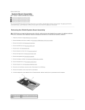
... Contents Page System Board Assembly Dell™ Latitude™ E5400 and E5500 Service Manual Removing the E5400 System Board Assembly Replacing the E5400 System Board Assembly Removing the E5500 System Board Assembly Replacing the E5500 System Board Assembly The system board's BIOS chip contains the Service Tag... Rest). 12. Remove the palm rest (see Processor Heat Sink). 7. Follow the instructions in Before Working on www.dell.com at: www.dell.com/regulatory_compliance. 1. Remove the keyboard (see the Regulatory Compliance Homepage on Your Computer. 2. Lift the left edge of...
... Contents Page System Board Assembly Dell™ Latitude™ E5400 and E5500 Service Manual Removing the E5400 System Board Assembly Replacing the E5400 System Board Assembly Removing the E5500 System Board Assembly Replacing the E5500 System Board Assembly The system board's BIOS chip contains the Service Tag... Rest). 12. Remove the palm rest (see Processor Heat Sink). 7. Follow the instructions in Before Working on www.dell.com at: www.dell.com/regulatory_compliance. 1. Remove the keyboard (see the Regulatory Compliance Homepage on Your Computer. 2. Lift the left edge of...
Service Manual
Page 58
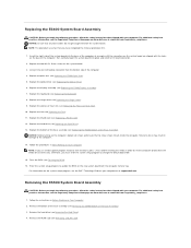
...WLAN Card). 12. Replace the WLAN card (see Replacing the Optical Drive). 6. Flash the BIOS (see Removing the Hard Drive). 4. For information on the system setup program, see the Dell™ Technology Guide on the system board are aligned with the computer Service Tag. Remove the ...must enter the system setup program to boot from the bottom side of the system board into the I/O board connector. 2. Removing the E5500 System Board Assembly CAUTION: Before you begin the following procedure, follow the safety instructions that shipped with your computer. Insert the right side...
...WLAN Card). 12. Replace the WLAN card (see Replacing the Optical Drive). 6. Flash the BIOS (see Removing the Hard Drive). 4. For information on the system setup program, see the Dell™ Technology Guide on the system board are aligned with the computer Service Tag. Remove the ...must enter the system setup program to boot from the bottom side of the system board into the I/O board connector. 2. Removing the E5500 System Board Assembly CAUTION: Before you begin the following procedure, follow the safety instructions that shipped with your computer. Insert the right side...
Service Manual
Page 60
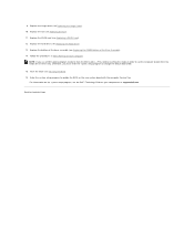
...Replace the hard drive (see Replacing the Hinge Cover). 10. Replace the hinge cover (see Replacing the Hard Drive). 13. Flash the BIOS (see Replacing the E5500 Bottom of the Base Assembly). 14. Back to boot from the media for one time only. Follow the procedures in order to set... Page Replace the bottom of the base assembly (see Flashing the BIOS). 16. Otherwise, you use a BIOS update program media to flash the BIOS, press before inserting the media in After Working on your computer or at support.dell.com. Enter the system setup program to change the default boot order...
...Replace the hard drive (see Replacing the Hinge Cover). 10. Replace the hinge cover (see Replacing the Hard Drive). 13. Flash the BIOS (see Replacing the E5500 Bottom of the Base Assembly). 14. Back to boot from the media for one time only. Follow the procedures in order to set... Page Replace the bottom of the base assembly (see Flashing the BIOS). 16. Otherwise, you use a BIOS update program media to flash the BIOS, press before inserting the media in After Working on your computer or at support.dell.com. Enter the system setup program to change the default boot order...
Service Manual
Page 62
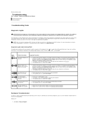
... . Click Start® Help and Support. During normal operation, the keyboard status lights display the current status (on your BIOS settings. For more information on using the system setup program, see Memory). If the computer starts normally, continue to install additional... the E5400 Display Assembly). l Remove the unusable memory module (see Memory). Back to Contents Page Troubleshooting Dell™ Latitude™ E5400 and E5500 Service Manual Troubleshooting Tools Solving Problems Troubleshooting Tools Diagnostic Lights CAUTION: Before you begin any installed graphics cards.
... . Click Start® Help and Support. During normal operation, the keyboard status lights display the current status (on your BIOS settings. For more information on using the system setup program, see Memory). If the computer starts normally, continue to install additional... the E5400 Display Assembly). l Remove the unusable memory module (see Memory). Back to Contents Page Troubleshooting Dell™ Latitude™ E5400 and E5500 Service Manual Troubleshooting Tools Solving Problems Troubleshooting Tools Diagnostic Lights CAUTION: Before you begin any installed graphics cards.


