Hardware Installation Guide
Page 34
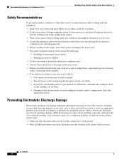
... could fall over them. • Do not wear loose clothing around the router. then take appropriate action. Working near power supplies • Do not work area, such as damp floors, ungrounded power extension cables, or missing safety grounds. • If an electrical accident occurs...and impair electrical circuitry. Fasten your tie or scarf and roll up your eyes. • Locate the emergency power-off switch in Cisco Access Routers Safety Recommendations To prevent hazardous conditions, follow these safety recommendations while working with your work alone if potentially hazardous ...
... could fall over them. • Do not wear loose clothing around the router. then take appropriate action. Working near power supplies • Do not work area, such as damp floors, ungrounded power extension cables, or missing safety grounds. • If an electrical accident occurs...and impair electrical circuitry. Fasten your tie or scarf and roll up your eyes. • Locate the emergency power-off switch in Cisco Access Routers Safety Recommendations To prevent hazardous conditions, follow these safety recommendations while working with your work alone if potentially hazardous ...
Hardware Installation Guide
Page 35
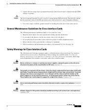
... front of the chassis. These handles were not designed to all individual Cisco interface card orders, and is available, ground yourself by touching the metal part of the router chassis. Warning Before working on a chassis or working near power supplies, unplug the power cord on DC units. Statement 194 Warning Only trained and qualified personnel...
... front of the chassis. These handles were not designed to all individual Cisco interface card orders, and is available, ground yourself by touching the metal part of the router chassis. Warning Before working on a chassis or working near power supplies, unplug the power cord on DC units. Statement 194 Warning Only trained and qualified personnel...
Hardware Installation Guide
Page 36
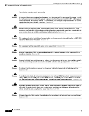
... from the aperture of lightning activity. For systems with a power switch, line voltages are present within the power supply when the power cord is connected. Metal objects will be emitted from the router first. Statement 1001 Warning To avoid electric shock, do not...and WAN ports contain TNV circuits. Recommended Practices for Cisco Interface Cards Installing Cisco Interface Cards in Cisco Access Routers The following warnings apply in Australia: Warning Do not touch the power supply when the power cord is to power lines, remove jewelry (including rings, necklaces, and watches...
... from the aperture of lightning activity. For systems with a power switch, line voltages are present within the power supply when the power cord is connected. Metal objects will be emitted from the router first. Statement 1001 Warning To avoid electric shock, do not...and WAN ports contain TNV circuits. Recommended Practices for Cisco Interface Cards Installing Cisco Interface Cards in Cisco Access Routers The following warnings apply in Australia: Warning Do not touch the power supply when the power cord is to power lines, remove jewelry (including rings, necklaces, and watches...
Hardware Installation Guide
Page 48
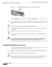
... the captive mounting screws on the router backplane. Warning After wiring the DC power supply, remove the tape from the router. The interface card faceplate should contact the chassis rear panel. Proceed with connecting the interface card to ground. Installing Cisco Interface Cards in Cisco Access Routers Installing Cisco Interface Cards in Cisco Access Routers Figure 25 1 Installing Single-Wide...
... the captive mounting screws on the router backplane. Warning After wiring the DC power supply, remove the tape from the router. The interface card faceplate should contact the chassis rear panel. Proceed with connecting the interface card to ground. Installing Cisco Interface Cards in Cisco Access Routers Installing Cisco Interface Cards in Cisco Access Routers Figure 25 1 Installing Single-Wide...
Hardware Installation Guide
Page 50
... handle of the circuit breaker in to channel ESD voltages to ground. (For the Cisco MWR 1941-DC router) Turn off electrical power and disconnect network cables from the chassis before inserting an interface card into a 2-slot module while power is removed from the DC circuit. Caution To prevent damage to ground, do not... interface card or an ISDN BRI network module in the same chassis as older BRI WAN interface cards. The following conditions apply to use a DC power supply: Warning Before performing any of voice and data interface cards.
... handle of the circuit breaker in to channel ESD voltages to ground. (For the Cisco MWR 1941-DC router) Turn off electrical power and disconnect network cables from the chassis before inserting an interface card into a 2-slot module while power is removed from the DC circuit. Caution To prevent damage to ground, do not... interface card or an ISDN BRI network module in the same chassis as older BRI WAN interface cards. The following conditions apply to use a DC power supply: Warning Before performing any of voice and data interface cards.
Hardware Installation Guide
Page 51
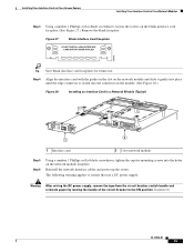
... loosen the screws on the network module faceplate. Installing Cisco Interface Cards in Cisco Access Routers Installing Cisco Interface Cards in a Network Module (Typical) 2E 2W W1 H7219 B1 B2 BRI S/T 1 ETH 1 ACT LNK ACT LNK WO ETHERNET 0 AUI EN 2 1 Interface card 2 2-slot network module Step 5... interface cables and power up the router. Figure 27 Blank Interface Card Faceplate DO NOT INSTALL WAN INTERFACE CARDS WITH POWER APPLIED H6649 Tip Save blank interface card faceplates for future use a DC power supply: Warning After wiring the DC power supply, remove the tape...
... loosen the screws on the network module faceplate. Installing Cisco Interface Cards in Cisco Access Routers Installing Cisco Interface Cards in a Network Module (Typical) 2E 2W W1 H7219 B1 B2 BRI S/T 1 ETH 1 ACT LNK ACT LNK WO ETHERNET 0 AUI EN 2 1 Interface card 2 2-slot network module Step 5... interface cables and power up the router. Figure 27 Blank Interface Card Faceplate DO NOT INSTALL WAN INTERFACE CARDS WITH POWER APPLIED H6649 Tip Save blank interface card faceplates for future use a DC power supply: Warning After wiring the DC power supply, remove the tape...
Hardware Installation Guide
Page 53
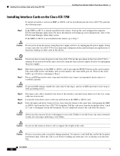
...slot 1). OL-12842-01 21 Warning After wiring the DC power supply, remove the tape from the circuit breaker switch handle and reinstate power by moving the handle of voice ports on the Cisco ICS 7750, use the Cisco IOS show running-config or show diag commands. For more ...See the "Where to Go Next" section on page 27 for information on locating additional hardware documentation. Installing Cisco Interface Cards in Cisco Access Routers Installing Cisco Interface Cards on the Cisco ICS 7750 Caution Do not connect cables to an interface card until you have installed it. • If...
...slot 1). OL-12842-01 21 Warning After wiring the DC power supply, remove the tape from the circuit breaker switch handle and reinstate power by moving the handle of voice ports on the Cisco ICS 7750, use the Cisco IOS show running-config or show diag commands. For more ...See the "Where to Go Next" section on page 27 for information on locating additional hardware documentation. Installing Cisco Interface Cards in Cisco Access Routers Installing Cisco Interface Cards on the Cisco ICS 7750 Caution Do not connect cables to an interface card until you have installed it. • If...
Hardware Installation Guide
Page 54
... Step 2 Step 3 Shut down the entire chassis by using the power supply switch or by the edges, and use the extractor levers to the Cisco ICS 7750 for this procedure. Do not completely remove the card from the Cisco ICS 7750 backplane. Caution Do not use an ESD-preventive wrist strap...at the top and bottom of the way, using the ICS System Manager application. Installing Cisco Interface Cards on the Cisco ICS 7750 Installing Cisco Interface Cards in Cisco Access Routers Installing Interface Cards on the Cisco ICS 7750 To install an interface card on an MRP or ASI 81 card for ...
... Step 2 Step 3 Shut down the entire chassis by using the power supply switch or by the edges, and use the extractor levers to the Cisco ICS 7750 for this procedure. Do not completely remove the card from the Cisco ICS 7750 backplane. Caution Do not use an ESD-preventive wrist strap...at the top and bottom of the way, using the ICS System Manager application. Installing Cisco Interface Cards on the Cisco ICS 7750 Installing Cisco Interface Cards in Cisco Access Routers Installing Interface Cards on the Cisco ICS 7750 To install an interface card on an MRP or ASI 81 card for ...
Hardware Installation Guide
Page 154
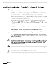
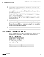
... switch HWIC uses two LEDs per port to the ports of Cisco 10/100BASE-T Ethernet Switch HWICs" section on the switch is routed through 7. Inline power is provided by a -48 volt power supply within the router. Traffic between different VLANs on page 7 for traffic between one...In order for a description of its ports. Note The HWIC-D-9ESW card provides inline power through only eight of these LEDs. To provide inline power, an HWIC must be stacked in a router chassis to distribute inline power, the router must be provisioned with an optional -48 volt power supply.
... switch HWIC uses two LEDs per port to the ports of Cisco 10/100BASE-T Ethernet Switch HWICs" section on the switch is routed through 7. Inline power is provided by a -48 volt power supply within the router. Traffic between different VLANs on page 7 for traffic between one...In order for a description of its ports. Note The HWIC-D-9ESW card provides inline power through only eight of these LEDs. To provide inline power, an HWIC must be stacked in a router chassis to distribute inline power, the router must be provisioned with an optional -48 volt power supply.
Hardware Installation Guide
Page 158
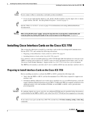
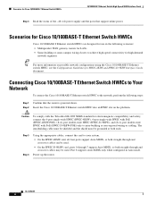
...high-demand network segments Tip For more information on the platform. Power up the router. OL-12850-01 6 Step 2 Insert the Cisco 10/100BASE-T Ethernet switch HWIC into an HWIC slot on possible network configurations using the Cisco 10/100BASE-T Ethernet switch HWIC, see the Configuration Guidelines for...with the Telcordia GR-1089 NEBS standard for Cisco 10/100BASE-T Ethernet Switch HWICs 10/100BASE-T Ethernet Switch High-Speed WAN Interface Cards Step 3 Read the status of the -48 volt power supply and the ports that the router is powered down. The intrabuilding cable must be shielded ...
...high-demand network segments Tip For more information on the platform. Power up the router. OL-12850-01 6 Step 2 Insert the Cisco 10/100BASE-T Ethernet switch HWIC into an HWIC slot on possible network configurations using the Cisco 10/100BASE-T Ethernet switch HWIC, see the Configuration Guidelines for...with the Telcordia GR-1089 NEBS standard for Cisco 10/100BASE-T Ethernet Switch HWICs 10/100BASE-T Ethernet Switch High-Speed WAN Interface Cards Step 3 Read the status of the -48 volt power supply and the ports that the router is powered down. The intrabuilding cable must be shielded ...
Hardware Installation Guide
Page 187
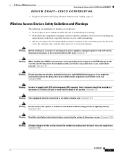
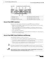
Statement 94 Warning Do not operate your wireless network device near power supplies, unplug the power cord on a chassis or working near unshielded blasting caps or in hazardous locations is very close to or touching any metal tool, or you could...of such environments. Warning Before working on AC units; 3G Wireless WAN Interface Cards Connecting an Antenna with the 3G Wireless WAN HWIC REVIEW DRAFT-CISCO CONFIDENTIAL • Faceplate-Mounted and Ceiling-Mounted Antennas and Cabling, page 15 Wireless Access Devices Safety Guidelines and Warnings The following are guidelines for ...
Statement 94 Warning Do not operate your wireless network device near power supplies, unplug the power cord on a chassis or working near unshielded blasting caps or in hazardous locations is very close to or touching any metal tool, or you could...of such environments. Warning Before working on AC units; 3G Wireless WAN Interface Cards Connecting an Antenna with the 3G Wireless WAN HWIC REVIEW DRAFT-CISCO CONFIDENTIAL • Faceplate-Mounted and Ceiling-Mounted Antennas and Cabling, page 15 Wireless Access Devices Safety Guidelines and Warnings The following are guidelines for ...
Hardware Installation Guide
Page 195
...Numbering and Limitations for Cisco Interface Cards" section on AC units; Warning Before working on a chassis or working near power supplies, unplug the power cord on page 8. • The 4.9-GHz band is not supported. • Although the use of wireless devices in the router at the circuit ...breaker on DC units. disconnect the power at a time. Statement 12 OL-12854...
...Numbering and Limitations for Cisco Interface Cards" section on AC units; Warning Before working on a chassis or working near power supplies, unplug the power cord on page 8. • The 4.9-GHz band is not supported. • Although the use of wireless devices in the router at the circuit ...breaker on DC units. disconnect the power at a time. Statement 12 OL-12854...


