Owners Manual
Page 3
...center 16 If your TV has audio output jacks 16 If your TV does not have audio output jacks 17 VCR considerations 18 Advanced setup options 18 Making S-video connections (higher quality video 18 Making component video connections (highest quality video 19 Connecting digital audio devices 20... the media center 20 Connecting a game console 22 Installing the remote control batteries 23 Connecting the power cord 24 Checking your system setup 25 System Controls and Indicators 26 Remote control 26 The media center 29 Control panel 29 Display indicators 29 Operation 30 Turning your ...
...center 16 If your TV has audio output jacks 16 If your TV does not have audio output jacks 17 VCR considerations 18 Advanced setup options 18 Making S-video connections (higher quality video 18 Making component video connections (highest quality video 19 Connecting digital audio devices 20... the media center 20 Connecting a game console 22 Installing the remote control batteries 23 Connecting the power cord 24 Checking your system setup 25 System Controls and Indicators 26 Remote control 26 The media center 29 Control panel 29 Display indicators 29 Operation 30 Turning your ...
Owners Manual
Page 5
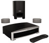
... 3•2•1 series II media center can enjoy your new system's performance right away. Then be sure to set up, so you for purchasing the Bose® 3•2•1 Series II or 3•2•1 GS Series II DVD home entertainment system, which must match. For example, a Region 1 DVD ... Acoustimass® module • Easy-to-use infrared remote control • Console input jacks for connecting other periods in an advanced home audio setup. Check the region code number on the carton of the 3•2•1 Series II DVD home entertainment system or on the disc label or ...
... 3•2•1 series II media center can enjoy your new system's performance right away. Then be sure to set up, so you for purchasing the Bose® 3•2•1 Series II or 3•2•1 GS Series II DVD home entertainment system, which must match. For example, a Region 1 DVD ... Acoustimass® module • Easy-to-use infrared remote control • Console input jacks for connecting other periods in an advanced home audio setup. Check the region code number on the carton of the 3•2•1 Series II DVD home entertainment system or on the disc label or ...
Owners Manual
Page 8
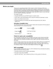
... speakers Rubber feet for speakers Remote control Batteries Stereo cable Video cable 240 VAC power cord (Australia) FM antenna Antenna stand AM antenna Setup and demo disc Note: Now is a good time to transport your system includes the parts shown in the carton. System... Setup Unpacking Figure 1 Contents of the shipping carton Your system includes one the following cords: 120 VAC power cord (US/Canada) 115/230 VAC power cord with a "GS". For Bose contact information, refer to be marked with adapter (US/Europe...
... speakers Rubber feet for speakers Remote control Batteries Stereo cable Video cable 240 VAC power cord (Australia) FM antenna Antenna stand AM antenna Setup and demo disc Note: Now is a good time to transport your system includes the parts shown in the carton. System... Setup Unpacking Figure 1 Contents of the shipping carton Your system includes one the following cords: 120 VAC power cord (US/Canada) 115/230 VAC power cord with a "GS". For Bose contact information, refer to be marked with adapter (US/Europe...
Owners Manual
Page 9
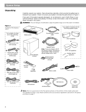
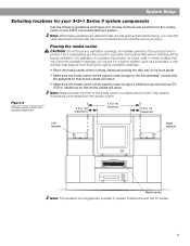
... 3 ft (1 m) maximum 3 ft (1 m) minimum 3 ft (1 m) maximum Left speaker Right speaker Media center Note: The speakers are more convenient and provide the sound you enjoy. System Setup Selecting locations for your 3•2•1 Series II system components Use the following guidelines and Figure 2 to choose locations and positions for the components of...
... 3 ft (1 m) maximum 3 ft (1 m) minimum 3 ft (1 m) maximum Left speaker Right speaker Media center Note: The speakers are more convenient and provide the sound you enjoy. System Setup Selecting locations for your 3•2•1 Series II system components Use the following guidelines and Figure 2 to choose locations and positions for the components of...
Owners Manual
Page 10
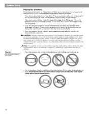
... Do not place the speakers at the front edge of the TV screen (Figure 2). Vibration can be ordered. • Place the speakers only on Bose brackets, table stands, or floor stands. If you to experience the audio surround effects that your 3•2•1 home entertainment system is designed to deliver... screen. Additional or longer cables may obtain additional rubber feet (part number 178321) from the listening area significantly alters system performance. 10 System Setup Figure 3 Recommended speaker placement Placing the speakers Choosing a good location for both speakers.
... Do not place the speakers at the front edge of the TV screen (Figure 2). Vibration can be ordered. • Place the speakers only on Bose brackets, table stands, or floor stands. If you to experience the audio surround effects that your 3•2•1 home entertainment system is designed to deliver... screen. Additional or longer cables may obtain additional rubber feet (part number 178321) from the listening area significantly alters system performance. 10 System Setup Figure 3 Recommended speaker placement Placing the speakers Choosing a good location for both speakers.
Owners Manual
Page 11
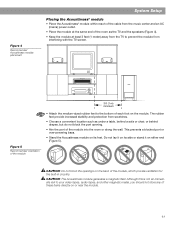
... other magnetic media, you should not store any of the module, which provide ventilation for the built-in circuitry. Figure 4 Recommended Acoustimass module placement System Setup Placing the Acoustimass® module • Place the Acoustimass® module within reach of the cable from interfering with the TV screen. MUSICCENTER ACINPUT CAUTION...
... other magnetic media, you should not store any of the module, which provide ventilation for the built-in circuitry. Figure 4 Recommended Acoustimass module placement System Setup Placing the Acoustimass® module • Place the Acoustimass® module within reach of the cable from interfering with the TV screen. MUSICCENTER ACINPUT CAUTION...

Owners Manual
Page 12
... module cable Acoustimass module input jack Connecting the speakers to the Acoustimass module 1. Make sure that the cable connectors only plug in the cable. System Setup Making system connections CAUTION: Do not plug the Acoustimass® module into an AC power (mains) outlet until all the components are needed to make...
... module cable Acoustimass module input jack Connecting the speakers to the Acoustimass module 1. Make sure that the cable connectors only plug in the cable. System Setup Making system connections CAUTION: Do not plug the Acoustimass® module into an AC power (mains) outlet until all the components are needed to make...

Owners Manual
Page 13
Note: If you purchased a 3•2•1 GS Series II system, the left and right speaker cords System Setup 2. Plug the LEFT speaker cable into the rear jack on the right speaker. Figure 9 Left and right speaker connections 3. At the other end of the ...
Note: If you purchased a 3•2•1 GS Series II system, the left and right speaker cords System Setup 2. Plug the LEFT speaker cable into the rear jack on the right speaker. Figure 9 Left and right speaker connections 3. At the other end of the ...
Owners Manual
Page 14
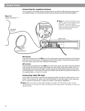
System Setup Figure 10 Antenna connections FM dipole antenna Connecting the supplied antennas The rear panel of the supplied indoor antennas. Note: An outdoor antenna may be ...
System Setup Figure 10 Antenna connections FM dipole antenna Connecting the supplied antennas The rear panel of the supplied indoor antennas. Note: An outdoor antenna may be ...

Owners Manual
Page 15
... and go to "Connecting your TV and VCR to the media center" on page 16. Such TVs are available at your local electronics store. 1. System Setup Connecting your TV to the media center Note: If you will need to select the corresponding video input on your TV in order to view...
... and go to "Connecting your TV and VCR to the media center" on page 16. Such TVs are available at your local electronics store. 1. System Setup Connecting your TV to the media center Note: If you will need to select the corresponding video input on your TV in order to view...

Owners Manual
Page 16
... Audio IN jacks on the back of the media center. If your TV has audio output jacks If your TV has audio output jacks. System Setup Connecting your TV and VCR to the media center Note: There are two options for example: Video 1, Input 1, or Aux). Before you proceed, you must...
... Audio IN jacks on the back of the media center. If your TV has audio output jacks If your TV has audio output jacks. System Setup Connecting your TV and VCR to the media center Note: There are two options for example: Video 1, Input 1, or Aux). Before you proceed, you must...

Owners Manual
Page 17
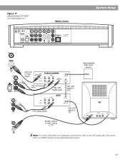
... TV 17 Insert the other end of the second video cable into the VIDEO OUT jack on the back of your VCR. System Setup Figure 13 System setup when TV has no audio output jacks If your TV does not have audio output jacks If your TV does not have audio output...
... TV 17 Insert the other end of the second video cable into the VIDEO OUT jack on the back of your VCR. System Setup Figure 13 System setup when TV has no audio output jacks If your TV does not have audio output jacks If your TV does not have audio output...

Owners Manual
Page 18
...red and white connectors) 18 For this connection you will need an S-video cable which can be purchased from a mono source. For this setup, you will need a Y-adapter cable (available at electronics stores) to connect audio to the media center. Figure 14 TV (S-video)-to-media... center connections Media center rear panel IMPORTANT If you have a mono VCR. Otherwise, you will simulate surround sound effects from your Bose dealer or a local electronics retailer. • Insert one audio output and is required for information. • A stereo VCR is not labeled...
...red and white connectors) 18 For this connection you will need an S-video cable which can be purchased from a mono source. For this setup, you will need a Y-adapter cable (available at electronics stores) to connect audio to the media center. Figure 14 TV (S-video)-to-media... center connections Media center rear panel IMPORTANT If you have a mono VCR. Otherwise, you will simulate surround sound effects from your Bose dealer or a local electronics retailer. • Insert one audio output and is required for information. • A stereo VCR is not labeled...

Owners Manual
Page 19
To do so, your local electronics store or authorized Bose dealer. 19 Note: For more information. Refer to the respective video input jack on page 47. If you connect an external video device to the C ... jacks (typically labelled Y, Pb, and Pr). If the cables are required in order to your TV. Figure 15 TV (component video)-tomedia center connections System Setup Making component video connections (highest quality video) Note: Component video connections are not supplied with your TV, you can purchase them separately. 1. For the highest...
To do so, your local electronics store or authorized Bose dealer. 19 Note: For more information. Refer to the respective video input jack on page 47. If you connect an external video device to the C ... jacks (typically labelled Y, Pb, and Pr). If the cables are required in order to your TV. Figure 15 TV (component video)-tomedia center connections System Setup Making component video connections (highest quality video) Note: Component video connections are not supplied with your TV, you can purchase them separately. 1. For the highest...

Owners Manual
Page 20
... your cable/satellite box, TV, and VCR to the media center The 3•2•1 home entertainment system provides flexibility for clarification on setup and usage before you can purchase the required cables at a local electronics store. Therefore, the media center output video is sent to ...satellite box audio source in the system settings menu. Use an optical digital cable or a coaxial digital cable, as appropriate, to connect this setup, please notice the following: • S-video connections are not able to decode a DTS bitstream from the internal DVD player can benefit ...
... your cable/satellite box, TV, and VCR to the media center The 3•2•1 home entertainment system provides flexibility for clarification on setup and usage before you can purchase the required cables at a local electronics store. Therefore, the media center output video is sent to ...satellite box audio source in the system settings menu. Use an optical digital cable or a coaxial digital cable, as appropriate, to connect this setup, please notice the following: • S-video connections are not able to decode a DTS bitstream from the internal DVD player can benefit ...
Owners Manual
Page 21
Figure 17 Advanced setup: TV, VCR and cable/satellite box Media center System Setup CBL-SAT S-video output Cable/satellite Cable/satellite (CBL-SAT) service CBL-SAT analog audio CBL-SAT digital audio VCR CBL-SAT signal to VCR TV VCR analog audio CBL-SAT signal to TV Media center's S-video output to TV Note: For more information on advanced connections, refer to the DVD setup disc that came with your 3•2•1 Series II home entertainment system. 21
Figure 17 Advanced setup: TV, VCR and cable/satellite box Media center System Setup CBL-SAT S-video output Cable/satellite Cable/satellite (CBL-SAT) service CBL-SAT analog audio CBL-SAT digital audio VCR CBL-SAT signal to VCR TV VCR analog audio CBL-SAT signal to TV Media center's S-video output to TV Note: For more information on advanced connections, refer to the DVD setup disc that came with your 3•2•1 Series II home entertainment system. 21

Owners Manual
Page 22
System Setup Figure 18 Game console connections Connecting a game console Connect the audio output of the game console to the C (composite) Video IN jack. Media center Game console connection panel TV connection panel IMPORTANT If you connected your game console this way, you will need to select the AUX source on the 3•2•1 remote in order to the AUX Left and Right input jacks. Connect the video output of a game console to hear sound from the game console. 22
System Setup Figure 18 Game console connections Connecting a game console Connect the audio output of the game console to the C (composite) Video IN jack. Media center Game console connection panel TV connection panel IMPORTANT If you connected your game console this way, you will need to select the AUX source on the 3•2•1 remote in order to the AUX Left and Right input jacks. Connect the video output of a game console to hear sound from the game console. 22

Owners Manual
Page 23
... the remote control stops operating or its range seems reduced. Insert the two supplied AA (IEC-R6) 1.5V batteries, or their equivalent, as shown. System Setup Installing the remote control batteries 1. Figure 19 Installing the batteries (2) AA batteries (IEC R6) + Battery + compartment door 23 Match the plus (+) and minus (-) marked on...
... the remote control stops operating or its range seems reduced. Insert the two supplied AA (IEC-R6) 1.5V batteries, or their equivalent, as shown. System Setup Installing the remote control batteries 1. Figure 19 Installing the batteries (2) AA batteries (IEC R6) + Battery + compartment door 23 Match the plus (+) and minus (-) marked on...

Owners Manual
Page 24
...: Provided only on 220-240V rated systems AC input jack 115V 115/230V selection switch Note: Provided only on the Acoustimass module (Figure 20). 2. System Setup Connecting the power cord CAUTION: For dual voltage models only, be sure to set the dual voltage switch on (l). Insert the large end of the...
...: Provided only on 220-240V rated systems AC input jack 115V 115/230V selection switch Note: Provided only on the Acoustimass module (Figure 20). 2. System Setup Connecting the power cord CAUTION: For dual voltage models only, be sure to set the dual voltage switch on (l). Insert the large end of the...
Owners Manual
Page 25
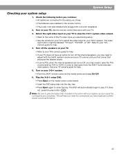
...3•2•1 system. Check the following before you chose. • The batteries were installed in order to your TV. 3. Play the 3•2•1 setup DVD. • Press Eject on your TV to view the 3•2•1 system video output. • Refer to the name of the TV video ...• In some TVs, when the internal speakers are completed. Select the right video input on the media center control panel. • Insert the DVD setup disc into a live AC receptacle. 2. Turn off , you find a level that came with your system, as soon as all the connections are turned...
...3•2•1 system. Check the following before you chose. • The batteries were installed in order to your TV. 3. Play the 3•2•1 setup DVD. • Press Eject on your TV to view the 3•2•1 system video output. • Refer to the name of the TV video ...• In some TVs, when the internal speakers are completed. Select the right video input on the media center control panel. • Insert the DVD setup disc into a live AC receptacle. 2. Turn off , you find a level that came with your system, as soon as all the connections are turned...