Setup Manual
Page 2
... ...3 Package Checklist ...3 Motherboard FeaturesS ...4 Rear Panel Connectors (for Ver 5.x) ...6 Rear Panel Connectors (for Ver 6.x)...6 Motherboard Layout...7 Installing Central Processing Unit (CPU) ...8 Fan Headers ...9 Installing System Memory ...10 Connectors and Slots ...11 How to Setup Jumpers ...13 Detail Settings ...13 Driver Installation Note...19 Award BIOS Beep Code ...20 Extra Information...20...
... ...3 Package Checklist ...3 Motherboard FeaturesS ...4 Rear Panel Connectors (for Ver 5.x) ...6 Rear Panel Connectors (for Ver 6.x)...6 Motherboard Layout...7 Installing Central Processing Unit (CPU) ...8 Fan Headers ...9 Installing System Memory ...10 Connectors and Slots ...11 How to Setup Jumpers ...13 Detail Settings ...13 Driver Installation Note...19 Award BIOS Beep Code ...20 Extra Information...20...
Setup Manual
Page 4
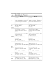
... 400 / 533 / 800 MHz VIA P4M900 VIA VT8237A Chrome9 HC 3D / 2D Graphics Max Shared Video Memory is 256 MB ITE 8718F Provides the most commonly used legacy Super I /O functionality. DDR2 Max Memory Capicity 4GB Single Channel Mode DDR2 memory module Registered DIMM and ECC DIMM is not..." function DIMM S lots x 2 Supports DDR2 533 / 667 95W power consumption. 400 / 533 / 800 MHz VIA P4M900 VIA VT8237A Chrome9 HC 3D / 2D Graphics Max Shared Video Memory is 256 MB ITE 8718F Provides the most commonly used legacy Super I /O functionality. Low Pin Count Interface Environment Control initiat...
... 400 / 533 / 800 MHz VIA P4M900 VIA VT8237A Chrome9 HC 3D / 2D Graphics Max Shared Video Memory is 256 MB ITE 8718F Provides the most commonly used legacy Super I /O functionality. DDR2 Max Memory Capicity 4GB Single Channel Mode DDR2 memory module Registered DIMM and ECC DIMM is not..." function DIMM S lots x 2 Supports DDR2 533 / 667 95W power consumption. 400 / 533 / 800 MHz VIA P4M900 VIA VT8237A Chrome9 HC 3D / 2D Graphics Max Shared Video Memory is 256 MB ITE 8718F Provides the most commonly used legacy Super I /O functionality. Low Pin Count Interface Environment Control initiat...

Setup Manual
Page 10
Align a DIMM on the slot such that the notch on the DIMM matches the break on the Slot. 2. Motherboard Manual 2.3 INSTALLING SYSTEM MEMORY A. Insert the DIMM vertically and firmly into the slot until the retaining chip snap back in place and the DIMM is 4GB. 10 DIMM1 DIMM2 B. Memory Capacity DIMM Socket Location DIMM1 DIMM2 DDR Module 256MB/512MB/1GB/2GB 256MB/512MB/1GB/2GB Total Memory Size Max is properly seated. Memory Modules 1. Unlock a DIMM slot by pressing the retaining clips outward.
Align a DIMM on the slot such that the notch on the DIMM matches the break on the Slot. 2. Motherboard Manual 2.3 INSTALLING SYSTEM MEMORY A. Insert the DIMM vertically and firmly into the slot until the retaining chip snap back in place and the DIMM is 4GB. 10 DIMM1 DIMM2 B. Memory Capacity DIMM Socket Location DIMM1 DIMM2 DDR Module 256MB/512MB/1GB/2GB 256MB/512MB/1GB/2GB Total Memory Size Max is properly seated. Memory Modules 1. Unlock a DIMM slot by pressing the retaining clips outward.
Setup Manual
Page 20
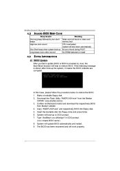
...restore BIOS. Type "Awdflash xxxx.bf/sn/py/r" in DOS prompt. (xxxx means BIOS name.) 8. Download the Flash Utility "AWDFLASH.exe" from Biostar website. 4. Copy "AWDFLASH.exe" and respectively BIOS into floppy drive and press Enter. 6. Insert the bootable disk into floppy disk. 5. If the...will update BIOS automatically and restart. 9. Motherboard Manual 4.2 AWARD BIOS BEEP CODE Beep Sound Meaning Video card not found or video card memory bad CPU overheated System will shut down automatically No error found during POST No DRAM detected or install One long beep followed by virus...
...restore BIOS. Type "Awdflash xxxx.bf/sn/py/r" in DOS prompt. (xxxx means BIOS name.) 8. Download the Flash Utility "AWDFLASH.exe" from Biostar website. 4. Copy "AWDFLASH.exe" and respectively BIOS into floppy drive and press Enter. 6. Insert the bootable disk into floppy disk. 5. If the...will update BIOS automatically and restart. 9. Motherboard Manual 4.2 AWARD BIOS BEEP CODE Beep Sound Meaning Video card not found or video card memory bad CPU overheated System will shut down automatically No error found during POST No DRAM detected or install One long beep followed by virus...
Setup Manual
Page 23
P4M900-M4 CHAPTER 5: WARPSPEEDER™ 5.1 INTRODUCTION [WarpSpeeder™], a new powerful control utility, features...in the About panel, you do not need to install DirectX 8.1.) 23 In addition, the frequency status of CPU, memory, AGP and PCI along with just one . 5.2 SYSTEM REQUIREMENT OS Support: Windows 98 SE, Windows Me, Windows ...8.1 or above. (The Windows XP operating system includes DirectX 8.1. Moreover, to power up CPU core voltage and Memory voltage. The cool Hardware Monitor smartly indicates the temperatures, voltage and CPU fan speed as well as the chipset ...
P4M900-M4 CHAPTER 5: WARPSPEEDER™ 5.1 INTRODUCTION [WarpSpeeder™], a new powerful control utility, features...in the About panel, you do not need to install DirectX 8.1.) 23 In addition, the frequency status of CPU, memory, AGP and PCI along with just one . 5.2 SYSTEM REQUIREMENT OS Support: Windows 98 SE, Windows Me, Windows ...8.1 or above. (The Windows XP operating system includes DirectX 8.1. Moreover, to power up CPU core voltage and Memory voltage. The cool Hardware Monitor smartly indicates the temperatures, voltage and CPU fan speed as well as the chipset ...
Setup Manual
Page 26
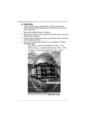
Display the CPU Speed, CPU external clock, Memory clock, AGP clock, and PCI clock information. Contains About, Voltage, Overclock, and Hardware Monitor Buttons for invoking respective panels. With a user-friendly Status Animation, it ...
Display the CPU Speed, CPU external clock, Memory clock, AGP clock, and PCI clock information. Contains About, Voltage, Overclock, and Hardware Monitor Buttons for invoking respective panels. With a user-friendly Status Animation, it ...
Setup Manual
Page 27
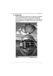
The default setting is "No". If you click the option "Yes". 27 P4M900-M4 3. In this panel, you can decide to get the best performance of overclocking, we recommend you want to increase CPU core voltage and Memory voltage or not. Voltage Panel Click the Voltage button in Main Panel, the button will be highlighted and the Voltage Panel will slide out to up as the following figure.
The default setting is "No". If you click the option "Yes". 27 P4M900-M4 3. In this panel, you can decide to get the best performance of overclocking, we recommend you want to increase CPU core voltage and Memory voltage or not. Voltage Panel Click the Voltage button in Main Panel, the button will be highlighted and the Voltage Panel will slide out to up as the following figure.
Bios Setup
Page 6
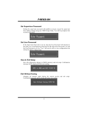
Save & Exit Setup Save all changes made during the current session and exit setup. P4M900-M4 Set Supervisor Password Setting the supervisor password will be able to change them. You will not be displayed before proceeding. 5 Set User Password If the ... with to enter a password. If the Supervisor Password is set and the User Password is not set , the "User" will only be able to CMOS (memory) and exit setup. Exit Without Saving Abandon all configuration changes to view configurations but will be displayed before proceeding. Confirmation message will function in the...
Save & Exit Setup Save all changes made during the current session and exit setup. P4M900-M4 Set Supervisor Password Setting the supervisor password will be able to change them. You will not be displayed before proceeding. 5 Set User Password If the ... with to enter a password. If the Supervisor Password is set and the User Password is not set , the "User" will only be able to CMOS (memory) and exit setup. Exit Without Saving Abandon all configuration changes to view configurations but will be displayed before proceeding. Confirmation message will function in the...

Bios Setup
Page 9
P4M900-M4 Item IDE Channel 1 Master IDE Channel 1 Slave Drive A Drive B Halt On Base Memory Extended Memory Total Memory Options Options are in its sub menu. Options are in which you want the BIOS to enter the sub menu of extended memory detected during boot up . Select the situation in its... enter the sub menu of floppy disk drive installed in the system. 8 Select the type of detailed options. Displays the total memory available in your system. Press to stop the POST process and notify you. Displays the amount of detailed options. Displays the amount of...
P4M900-M4 Item IDE Channel 1 Master IDE Channel 1 Slave Drive A Drive B Halt On Base Memory Extended Memory Total Memory Options Options are in its sub menu. Options are in which you want the BIOS to enter the sub menu of extended memory detected during boot up . Select the situation in its... enter the sub menu of floppy disk drive installed in the system. 8 Select the type of detailed options. Displays the total memory available in your system. Press to stop the POST process and notify you. Displays the amount of detailed options. Displays the amount of...
Bios Setup
Page 13
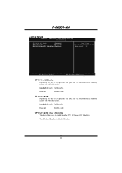
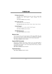
CPU L3 Cache Depending on the CPU/chipset in use , you may be able to increase memory access time with this option. Enabled (default) Enable cache. Disab led Disable cache. The Choices: Enabled (default), Disabled. 12 CPU L2 Cache ECC Checking This item allows you to enable/disable CPU L2 Cache ECC Checking. Enabled (default) Enable cache. Cache Setup P4M900-M4 CPU L1 & L2 Cache Depending on the CPU/chipset in use , you may be able to increase memory access time with this option. Disab led Disable cache.
CPU L3 Cache Depending on the CPU/chipset in use , you may be able to increase memory access time with this option. Enabled (default) Enable cache. Disab led Disable cache. The Choices: Enabled (default), Disabled. 12 CPU L2 Cache ECC Checking This item allows you to enable/disable CPU L2 Cache ECC Checking. Enabled (default) Enable cache. Cache Setup P4M900-M4 CPU L1 & L2 Cache Depending on the CPU/chipset in use , you may be able to increase memory access time with this option. Disab led Disable cache.
Bios Setup
Page 17
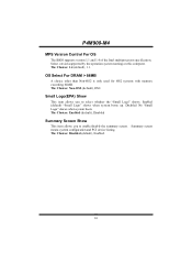
...Logo" shows when system boots up. OS Select For DRAM > 64MB A choice other than Non-OS2 is only used for OS2 systems with memory exceeding 64MB. Small Logo(EPA) Show This item allows you to select whether the "Small Logo" shows. Disabled No "Small Logo" shows ... The Choices: Disabled (default), Enabled. 16 Summary screen means system configuration and PCI device listing. The Choices: Non-OS2 (default), OS2. P4M900-M4 MPS Version Control For OS The BIOS supports version 1.1 and 1.4 of the Intel multiprocessor specification. Select version supported by the operation system running ...
...Logo" shows when system boots up. OS Select For DRAM > 64MB A choice other than Non-OS2 is only used for OS2 systems with memory exceeding 64MB. Small Logo(EPA) Show This item allows you to select whether the "Small Logo" shows. Disabled No "Small Logo" shows ... The Choices: Disabled (default), Enabled. 16 Summary screen means system configuration and PCI device listing. The Choices: Non-OS2 (default), OS2. P4M900-M4 MPS Version Control For OS The BIOS supports version 1.1 and 1.4 of the Intel multiprocessor specification. Select version supported by the operation system running ...
Bios Setup
Page 18
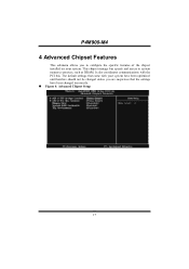
The default settings that the settings have been changed incorrectly. „ Figure 4: Advanced Chipset Setup 17 This chipset manage bus speeds and access to configure the specific features of the chipset installed on your system have been optimized and therefore should not be changed unless you are suspicious that came with the PCI bus. It also coordinates communications with your system. P4M900-M4 4 Advanced Chipset Features This submenu allows you to system memory resources, such as DRAM.
The default settings that the settings have been changed incorrectly. „ Figure 4: Advanced Chipset Setup 17 This chipset manage bus speeds and access to configure the specific features of the chipset installed on your system have been optimized and therefore should not be changed unless you are suspicious that came with the PCI bus. It also coordinates communications with your system. P4M900-M4 4 Advanced Chipset Features This submenu allows you to system memory resources, such as DRAM.
Bios Setup
Page 19
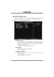
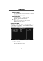
P4M900-M4 AGP & P2P Bridge Control Highlight "Press Enter" next to the "AGP & P2P Bridge Control" label and pressing the enter key will take you to the ... hit the aperture range are executed with the following options: „ Figure 4.1: AGP & P2P Bridge Control AGP Aperture Size Select the size of the PCI memory address range dedicated for graphics...
P4M900-M4 AGP & P2P Bridge Control Highlight "Press Enter" next to the "AGP & P2P Bridge Control" label and pressing the enter key will take you to the ... hit the aperture range are executed with the following options: „ Figure 4.1: AGP & P2P Bridge Control AGP Aperture Size Select the size of the PCI memory address range dedicated for graphics...
Bios Setup
Page 20
P4M900-M4 AGP Master 1 WS Read When enabled, read to the PCI bus are executed with zero-wait states. CPU & PCI Bus Control By highlighting the "Press ... Frame Buffer This item allows you to disabled or enabled direct frame buffer The Choices: Enabled (default), Disabled. The Choices: Enabled (default), Disabled. VGA Share Memory Size This item allows you to select the VGA share...
P4M900-M4 AGP Master 1 WS Read When enabled, read to the PCI bus are executed with zero-wait states. CPU & PCI Bus Control By highlighting the "Press ... Frame Buffer This item allows you to disabled or enabled direct frame buffer The Choices: Enabled (default), Disabled. The Choices: Enabled (default), Disabled. VGA Share Memory Size This item allows you to select the VGA share...
Bios Setup
Page 21
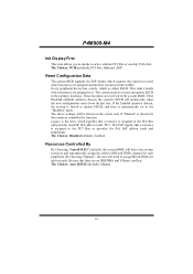
... can reserve this area of system memory for ISA adapter ROM. Check the user information of peripherals that attempts to write to this area is able to use this area of the ... Choices: Disabled (default), Enabled. Top Performance The Choices: Disabled (default), Enabled. 20 System BIOS Cacheable Selecting the "Enabled" option allows caching of system memory for the memory requirements. P4M900-M4 PCI Delay Transaction The chipset has an embedded 32-bit posted write buffer to enable or disable VLink 8X support. The Choices: By Auto...
... can reserve this area of system memory for ISA adapter ROM. Check the user information of peripherals that attempts to write to this area is able to use this area of the ... Choices: Disabled (default), Enabled. Top Performance The Choices: Disabled (default), Enabled. 20 System BIOS Cacheable Selecting the "Enabled" option allows caching of system memory for the memory requirements. P4M900-M4 PCI Delay Transaction The chipset has an embedded 32-bit posted write buffer to enable or disable VLink 8X support. The Choices: By Auto...
Bios Setup
Page 34
... "Disabled" mode. Every peripheral device has a node, which signifies that a resource is chosen for each peripheral. PCI / ISA PnP signify that a resource is called ESCD. P4M900-M4 Init Display First This item allows you to decide to active whether PCI Slot or on cards. Legacy is the term, which is assigned to...
... "Disabled" mode. Every peripheral device has a node, which signifies that a resource is chosen for each peripheral. PCI / ISA PnP signify that a resource is called ESCD. P4M900-M4 Init Display First This item allows you to decide to active whether PCI Slot or on cards. Legacy is the term, which is assigned to...


